Adewale Adeyinka A.1, Adagunodo Emmanuel R.2, John Samuel N.1, Ndujiuba Charles1
1Covenant University, Canaanland, Ota, Nigeria
2Obafemi Awolowo University, Ile-Ife, Nigeria
Correspondence to: Adewale Adeyinka A., Covenant University, Canaanland, Ota, Nigeria.
| Email: |  |
Copyright © 2016 Scientific & Academic Publishing. All Rights Reserved.
This work is licensed under the Creative Commons Attribution International License (CC BY).
http://creativecommons.org/licenses/by/4.0/

Abstract
The need for improved network performance towards providing reliable services in the face of growing demand on enterprise network and internet service across all sectors of the economy has become very paramount. Latency and packet loss as quality of service (QoS) metrics are issues of concern since different multimedia applications, voice and data packets have to be delivered to end systems over long distances. This study investigated the technology behind the delivery of the packets by comparing the performance of each of IP, MPLS and MPLS-TE on the same congested WAN design. The results showed that MPLS-TE had the least latency and barely any packet loss.
Keywords:
IP, MPLS, MPLS-TE, Latency, Packet Loss, Congestion
Cite this paper: Adewale Adeyinka A., Adagunodo Emmanuel R., John Samuel N., Ndujiuba Charles, A Comparative Simulation Study of IP, MPLS, MPLS-TE for Latency and Packet Loss Reduction over a WAN, International Journal of Networks and Communications, Vol. 6 No. 1, 2016, pp. 1-7. doi: 10.5923/j.ijnc.20160601.01.
1. Introduction
An increase in the number of users and deployment of new applications, memory intensive applications and devices contending for network resources have necessitated the need for improvement in the overall architecture of internet and enterprise networks. Hence, an ever evolving model, technologies and devices to match are needed [1]. The network designer is faced with the challenge of optimizing network performance at lowest cost for maximum operation. IP Networks are used for data exchange on the internet, but in spite of its good functionality; it is no longer enough to provide the needed quality of service for delay sensitive applications. IP packet forwarding analyzes the destination IP address contained in the network layer header of each packet as the packet travels from its source to its final destination. Multiprotocol label switching (MPLS) uses labels which are advertised between routers so that they can build a label-to-label mapping. These labels are attached to the IP packets, enabling the routers to forward the traffic by looking at the label and not the destination IP address that is packets are forwarded by label switching instead of by IP switching resulting in greater speed of delivery of packets [3, 5]. Some of the problems associated with a poorly designed network include congestion, poor mapping of mapping of traffic streams to network resources, poor redundancy and backup links resulting in poor service quality (IP telephony, IP video and wireless communications) in terms of the latency, jilter and loss of packets [2]. Traffic Engineering (TE) can be used to resolve some of these design flaws and improve overall network performance of the Core/ Backbone, enterprise topology, branch / WAN, data center, and Internet edge [4]. This research examined the effects of MPLS and traffic engineering (MPLS-TE) on latency and packet loss in a congested WAN (enterprise network) by simulation study using GNS3. The rest of this paper is divided into four sections. The literature review comes after this section followed by network design in section 3. The section 4 is the implementation followed by a conclusion of the paper.
2. Literature Review
Routing in IP networks is governed by the need to get the traffic across the network as quickly as possible. That is why IP routing is based on the least-cost routing principle. Every IP routing protocol has a cost associated with the links in the networks. In MPLS, devices that support IP forwarding, the IP routing tables are used to build IP forwarding tables, also called forwarding information base (FIB) [6, 7]. After the IP routing tables have been built, MPLS labels are assigned to individual entries in the IP routing table (individual IP prefixes) and propagated to adjacent MPLS devices through a Label Distribution Protocol (LDP). Every label assigned by an MPLS device is entered as an input label in its label forwarding information base (LFIB), which is the forwarding table used for label switching [9].Most label assignments, both local as well as those made by adjacent devices, are entered into a table called the label information base (LIB). The label that the IP next-hop assigns for a particular IP prefix is entered as an output label in the local LFIB to enable pure label forwarding. In devices that support IP forwarding, such a label is also entered into the FIB to support IP-to-label forwarding. After the IP routing tables, IP forwarding tables, and label forwarding tables have been built, the MPLS devices can start to forward IP traffic. All MPLS devices must support label forwarding; whenever they receive a labeled packet, they perform a label lookup in the LFIB, replace the input label with the output label, and forward the labeled packet to the next-hop LSR. Some MPLS devices (ingress LSRs) can receive IP datagrams, perform a lookup in the FIB, insert an MPLS label stack in front of the IP datagram based on information stored in the FIB, and forward the labeled packet to the next-hop LSR. The PE router within the MPLS VPN architecture is an example of such a device. Other MPLS devices (egress LSR) can receive labeled packets, perform an LFIB lookup, and (based on the absence of an output label in the LFIB) remove the label from the ingress labeled datagram and forward the IP datagram to the next-hop IP router [11]. MPLS Traffic Engineering (MPLS-TE) is a growing implementation in today's service provider (SP) networks. MPLS adoption in SP networks has increased greatly due to its inherent TE capabilities. The SPs use the MPLS-TE to ensure reliability and fast movement of data over the network, as it essential for SPs to recognize networks which need to be managed, secured and made reliable for the resources of the network for customers [2, 11].MPLS-TE allows for a TE scheme where the head end router of a label switched path (LSP) can calculate the most efficient route through the network toward the tail end router of the LSP [4, 6, 10]. TE consists of three main steps which are measure, model and control. The operator measures the physical layout of the network which is necessary for tasks like capacity planning and network visualization followed by estimation of possible settings of the links, knowing how much an IGP setting affects the traffic flow. IGP protocol is a routing protocol which is used with the group of IP networks under the control of one entity which gives a common routing policy for the internet [6, 11]. The Cisco IOS IP Service Level Agreements (SLAs) Internet Control Message Protocol (ICMP) echo operation is used to monitor end-to-end response time between a Cisco router and devices using IP. Also, ICMP echo is useful for troubleshooting network connectivity issues. IP SLAs is a portfolio of technology embedded in most devices that run Cisco IOS software, which allows Cisco customers to analyze IP service levels for IP applications and services, to increase productivity, to lower operational costs, and to reduce the frequency of network outages [12].The law of large numbers (LLN), which states that as an experiment is repeated, the observed frequency of a specific outcome approaches the theoretical frequency of that outcome over an entire population is the statistical concept employed by Traffic Engineering. The LLN when put in telecommunication terms simply means that the overall behavior of a large network can be predicted with reasonable certainty even if the behavior of any single packet cannot be predicted. If the level of network traffic nears, reaches or exceeds the design maximum, the network is said to be congested. In a telephone network, traffic is measured in call seconds (CCS) or erlangs. One CCS is equal to 100 seconds of telephone time. One erlang is equal to one hour or 36 CCS of telephone time. If a subscriber attempts to send a message or place a call in a congested network, one of three things may occur which includes: rejection, return or loss of a message, the user may receive a busy signal, a message can be placed in a queue and is eventually delivered according to set parameters. The network is said to be in a high-loss condition when message queues become unacceptably lengthy or the frequency of busy signals becomes unacceptably high, one of the major objectives of traffic engineering is to reduce high-loss situations. Under normal circumstances the number of rejected messages or failed call attempts should be as close to zero as possible. Balancing the quality of service against the cost of operation and maintenance of the network are other goals of TE [13].When multiple TE tunnels have the same cost, traffic can be load-balanced across them. Traffic can also be load-balanced between the native IP path and TE tunnels if the cost of the routing is the same. A times, the load balancing can be unequal cost load balancing hence, the load balancing of traffic is weighted proportionally to the bandwidth requirement of the TE tunnels that is If you have one tunnel with 60 MB and one with 40 MB of reserved bandwidth, the load-balancing ratio is 3:2, or the first tunnel should get one and a half times more traffic than the second tunnel. However, the load-balancing ratio is an approximation, because Cisco Express Forwarding (CEF) has only 16 hash buckets [14]. When an LSR performs the load balancing over one or more IP paths and one or more TE tunnels, it is always equal cost load balancing. This means that every path gets the same amount of traffic. Multiple TE tunnels can be handy when the amount of bandwidth to be reserved between a pair of routers is more than the bandwidth capacity of the links. You can then just create multiple TE tunnels with each a piece of the required bandwidth.IP routing is a rather general name for an assemblage of protocols that accomplish routing by implementing specific routing algorithm. Routing is the transfer of a packet from a device on one network to a device on a different network. IP routing protocols allow routers to build up forwarding tables that correspond with final destinations and next hop addresses. Some of the routing protocols are: IGRP (Interior Gateway Routing Protocol) which operates within an autonomous system (AS) that is a system under single administration. OSPF (Open Shortest Path First) a link state protocol that uses speed as its metric. RIP (routing Information Protocol) is a distance vector protocol [12, 14].
3. Network Design/Implementation
It is envisaged that when the core network is congested (flooded) with packets or occurrence of a link failure, there is tendency of high latency in the core network and communication between the layers may become practically impossible over the network. This scenario was created in this design and was used as the basis of comparison of the IPv4 and the label switching techniques and its traffic engineering techniques.Meanwhile, practice in network designs has shown that a network should be built in a hierarchical and modular way. This is to ensure scalability, redundancy and limitation of the size of failure domains if they occur. The network was designed following the Cisco recommended hierarchical model as in figure1. It utilized a layer 3 routed core to which the other architectural building blocks were connected. Basic layer 3 connectivity were established in the core and between distribution switches before virtualization. MPLS was enabled on all interfaces connected to providers’ routers and on all interfaces interconnecting the distribution layer switches and globally in the router configuration. MPLS labels were exchanged for all routes in the routers IPv4 routing table each having its own label protocol. This can be seen from the MPLS forwarding table of any provider edge (PE) router.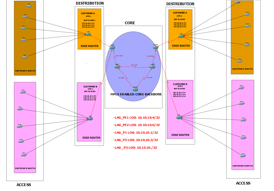 | Figure 1. Hierarchical Block diagram |
MPLS forwarding-table build-up is shown in figure 2. Among others, it showed the incoming and outgoing label tags for the packets through each of the router interfaces. For MPLS VPNs to work appropriately, the control plane and data plane have to be successfully built. BGP (Border gateway protocol) was used for the buildup of the control plane. The control plane holds all routes advertised in and into the routing domain. It is chosen because due to its possession of extended communities, larger-than-32bit routes can be sent over the network. In other words, it is capable of carrying overlapping IP addresses unlike other routing protocols.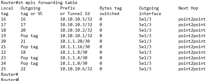 | Figure 2. Buildup of MPLS Forwarding table |
The core was kept BGP free. In fact, the purpose of the provider P routers is to label switch routes and provide a high speed connection between PE routers. Now that the control plane has been built, the data plane for each virtual network (VRF) was created and then populated. This is done by the creation of VRF instances on the PE/distribution routers and then the mapping of the respective VLANS in each distribution block to the appropriate VRF.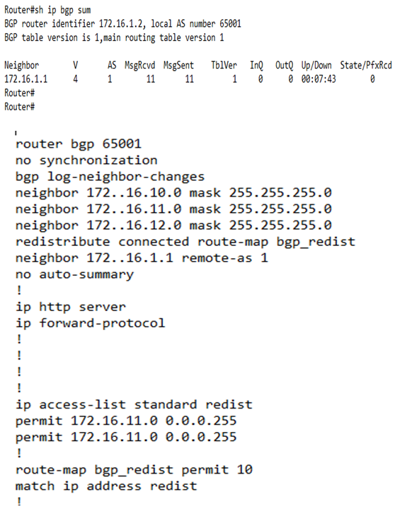 | Figure 3. Configuration of BGP customer edge (CE) -PE on Route Reflectors for Control Plane Buildup |
Traffic engineering (TE) was enabled globally and on interfaces that were possible candidates for TE paths. Resource reservation protocol (RSVP) as an extension of the resources reservation protocol for traffic engineering was used to reserve resources and indicate nature (bandwidth, jitter, maximum burst) of the packet streams received across the IP network. In MPLS-TE, the command used to establish a tunnel on the network or through routers is MPLS TRAFFIC-ENG TUNNELS which was entered globally and on the interface level. In the IP rsvp band X Y, X states the size of the possible pool and Y states the size of a single traffic flow. The tunnel destination is LAG_PE2 and it has a Loopback interface IP of 10.10.10.6. The ‘tunnel mpls traffic-eng priority X Y’, X is the set-up priority which was used when signaling an LSP to determine which existing LSP can be pre-emptied, Y is hold priority which was used to determine whether the LSP should be pre-emptied by other LSPs with lower priority. The ‘tunnel mpls traffic-eng bandwidth’ specified the LSP’s bandwidth. Path-option configured the tunnel to use a named IP explicit path or a path dynamically calculated from the traffic engineering topology database as shown in figure 4 and 5, tunnel1 and tunnel 2 respectively. A dynamic path is used if an explicit path is currently unavailable. The ‘tunnel mpls traffic-eng AutoRoute announce’ command, configured the tunnel interface to be announced into the IGP routing table.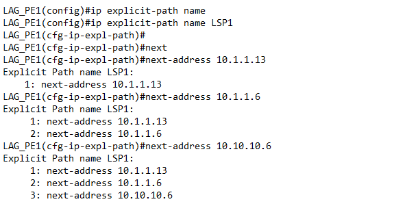 | Figure 4. Tunnel 1 (LSP1), Explicit Path Addresses Configuration |
In this configurations (that is figure 4 and 5), the IGP is OSPF and all the above configurations were carried out on all LSRs that are possible candidate for TE path-options. Cisco IOS IP Service Level Agreements (SLAs) ICMP echo operation was used to monitor end-to-end response time and troubleshoot network connectivity issues between a router and devices using IP.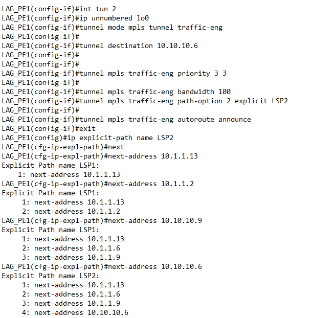 | Figure 5. Tunnel 2 (LSP2), Explicit Path Addresses Configuration |
4. Results
Each router was connected using a four port serial link into the slot one 1 space provided. Open Shortest Path First (OSPF) as an open standard routing protocol being implemented by a lot of network vendors was used as routing protocol for this design and the network simulator employed was GNS3. Wireshark was used to monitor packet loss. To increase scalability, the Resource Reservation Protocol (RSVP) was used to automate the procedure. The packets forwarded according to MPLS-TE had a stack of two labels (imposed by the ingress router). The top-most label identifies a specific LSP to use to reach another router at the other end of the tunnel. The second label indicates what the router at the far end of the LSP should do with the packet. By selecting the appropriate LSP, traffic can be directed explicitly. Some of the configurations and tunnels setup are shown below in Figures 6 to 8.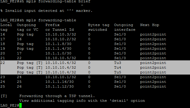 | Figure 6. Successful Build-up of Tunnels Across Router Interfaces |
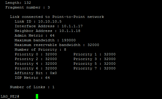 | Figure 7. OSPF OPAQUE LSA |
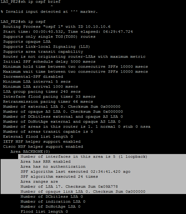 | Figure 8. Verifying MPLS-TE for OSPF |
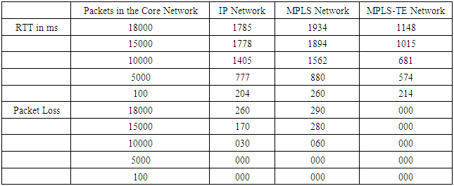
This shows the extension of all the operation occurring in the network involving MPLS and MPLS-TE.The IP, MPLS and MPLS-TE networks were of the same topology and were subjected to the same ping tests. The network in turn was congested with increasing number of packet in the core network and ping tests were carried out to measure the latency (RTT). The results of the ping tests are presented in Table1 below. It should be noted that once an MPLS network is disabled, it operates as an IPv4 network.Table 1. Values of RTT and Packet loss for each Network Protocol
 |
| |
|
The graphical views of the results are illustrated graphically in Figure12 and Figure13.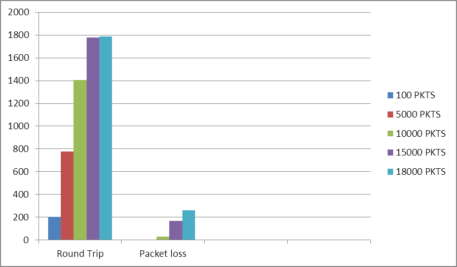 | Figure 9. Latency and Packet Loss of IP Network |
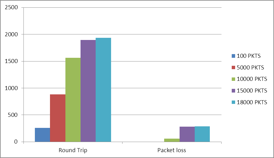 | Figure 10. Latency and Packet loss of MPLS |
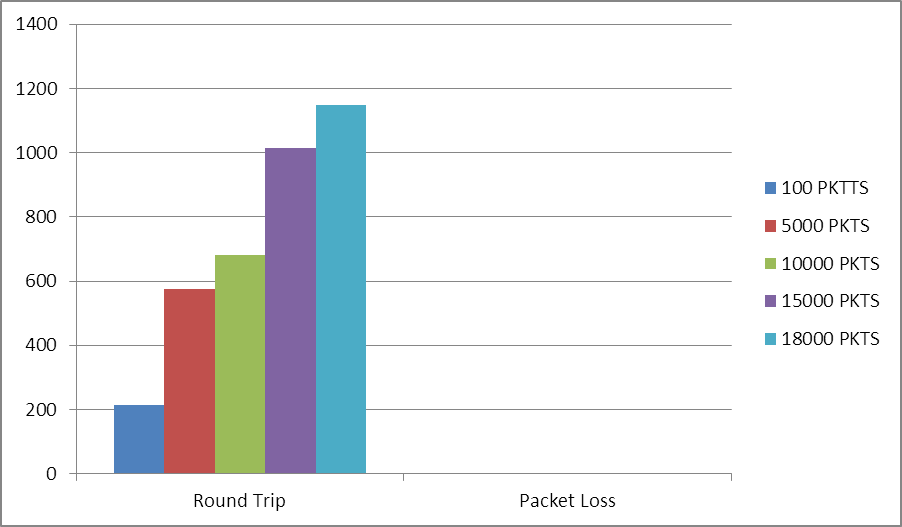 | Figure 11. Latency for MPLS-TE Network |
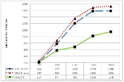 | Figure 12. Comparison of Latencies of IP/MPLS/MPLS TE over a WAN |
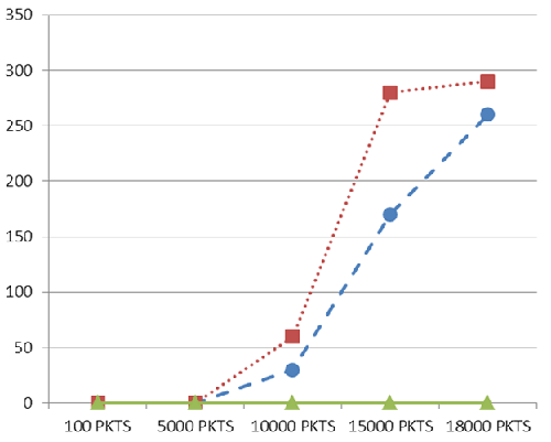 | Figure 13. Comparison of Packet Loss over a WAN |
In the line graph in the Figure12 below, for an IP network there is an increase in the round trip time for it to send packets, also in the MPLS network there is slight reduction RTT from that of the IP network while the reduction is substantial for MPLS-TE.The line graph of Figure13 showed that, for an IP network there is an increase in the number of packet loss when sending packets and also the same for an MPLS Network but no packet loss was noticed for the for MPLS-TE when sending packets.
5. Conclusions
The MPLS-TE solution has been used as a network virtualization or path isolation tool in service provider core networks to improve the redundancy of the MPLS and MPLS VPN. However, with slight modification to its logic, it can be applied to the campus enterprise network and when this is done, it provides ability to create as many networks as possible, redundancy, load balancing, backup route and link protection. The need for network planning and traffic engineering in a core network has driven multiprotocol label switching traffic engineering (MPLS-TE) towards becoming a standard within service provider core networks. The explosive growth of the Internet presents serious challenge to service providers and equipment sellers in terms of traffic escalation. There is also the demand to create differentiated IP services and other challenges include the cost of mapping IP over layer 2 networks, as well as difficulties in identifying better network utilization and fault handling. However, this research has shown by simulation experiments comparison between IP, MPLS and the MPLS-TE network. The results showed a drastic reduction in latency and no packet loss as the network becomes more congested for the MPLS-TE network implying that traffic engineering combined with label switching will be a good option to decongest a core network or service provider network.
References
| [1] | F. Baker Requirements for IP Version 4 Routers, RFC1812, June 1995. |
| [2] | Network Virtualization - Path Isolation Design Guide, Cisco Validated Design, 2009. |
| [3] | D. O. Awduche, “MPLS and Traffic Engineering in IP Networks,” University of Minnesota, IEEE communication magazine, December 1999. |
| [4] | D. Awduche, A. Chiu, A. Elwalid, I. Widjaja, X. Xiao “Overview and Principles of Internet Traffic Engineering”, RFC 3272, May 2002. |
| [5] | B. Fortz, J. Rexford, M. Thorup, “Traffic Engineering with Traditional IP Routing Protocols” IEEE Communications Magazine, October 2002. |
| [6] | K. G. Coffman, A. M. Odlyzko, “Internet growth: Is there a Moore’s Law for data traffic?” AT&T Labs – Research Revised version, June 4, 2001. |
| [7] | D. D. Clark, W. Fang, “Explicit Allocation of Best-Effort Packet Delivery Service”, IEEE/ACM Transactions on Networking (TON) Volume 6 Issue 4, 1998, pp. 362-373. |
| [8] | V. P. Kumar, T. V. Lakshman, D. Stiliadis, “Beyond Best Effort: Router Architectures for the Differentiated Services of Tomorrow’s Internet”, IEEE Communications Magazine, May, 1998. |
| [9] | Guichard and Pepelnjak, MPLS and VPN Architectures, Volume I, Cisco Press, 2001. |
| [10] | Callon, Rosen and Visawanathan, RFC 3031, Multiprotocol Label Switching Architecture, January 2001. |
| [11] | Guichard and Pepelnjak, MPLS and VPN Architectures, Volume II, Cisco Press, 2001. |
| [12] | Cisco documents: IP slas-analyzing IP service levels using the ICMP ECHO operation.www.cisco.com/en/US/docs/ios/12_4/ip_sla/configuration/guide/hsoverv.html. Retrieved, May 2014. |
| [13] | Villy B. Iversen, “Teletraffic Engineering and Network Planning”, Technical University of Denmark, DK-2800 Kgs-Lyngby, Revised May 20, 2010. Retrieved June10, 2015 from http://oldwww.com.dtu.dk/education/34340. |
| [14] | Todd Lammle, CCNA: Cisco Certified Network Associate Study Guide, 6th Edition, Wiley Publishing, 2007. |

 Abstract
 Reference
 Full-Text PDF
 Full-text HTML