Mahmudul Haque Kafi1, Joarder Jafor Sadique2, Sk. Shifatul Islam1
1Department of Applied Physics and Electronic Engineering, Rajshahi University, Rajshahi, Bangladesh
2Department of Electronics and Telecommunication Engineering, Begum Rokeya University, Rangpur, Bangladesh
Correspondence to: Sk. Shifatul Islam, Department of Applied Physics and Electronic Engineering, Rajshahi University, Rajshahi, Bangladesh.
| Email: |  |
Copyright © 2015 Scientific & Academic Publishing. All Rights Reserved.
Abstract
In this paper, an effort has been made to observe critically the impact of various channel coding and signal detections techniques in MGSTC BLAST Spatial Multiplexing scheme aided mmWave system on encrypted color image transmission .The simulated system incorporates MMSE, Q-less QR, BLUE and ZF as signal detection and Turbo and Repeat and Accumulate as channel coding under QAM, PSK digital modulations schemes under 4 × 4 antenna configuration. It is noticeable from MATLAB based simulative study that the system shows quite satisfactory performance in retrieving transmitted color image under scenario of hostile fading channel environment with implementation of MMSE signal detection, QAM digital modulation and Turbo channel coding scheme.
Keywords:
Keywords MGSTC, mmWave MIMO channel, Signal to noise ratio (SNR), MMSE, Q-less QR, ZF and BLUE
Cite this paper: Mahmudul Haque Kafi, Joarder Jafor Sadique, Sk. Shifatul Islam, Performance Analysis of MGSTC BLAST Spatial Multiplexing Scheme Aided mmWave System on Encrypted Color Image Transmission, International Journal of Networks and Communications, Vol. 5 No. 4, 2015, pp. 67-73. doi: 10.5923/j.ijnc.20150504.01.
1. Introduction
Wireless communication has become pervasive in our world and is acting as a transformative medium allowing our work, education, and entertainment to be transported without any physical connection. With tremendous development in telecommunication sector, it is being observed that nearly 50% of the traffic in cellular networks today is video. Due to explosive demand for high quality video streaming from mobile devices (e.g., tablets, smart-phones), the mobile network operators (MNOs) are facing unprecedented challenge to offer higher data rates that can keep up with this demand for high quality video. With the ever increasing demands in higher data rate, there is a growing interest in exploiting massive amount of unlicensed millimetre-wave spectrum (30-300 GHz), for next generation(5G) Network. The mmWave wireless communication can be treated as an enabling technology that has myriad applications to existing and emerging wireless networking deployments. The first step in a mmWave communications revolution is 60 GHz WPAN and WLAN deployment. To accommodate continued growth in the Internet and cloud-based applications, Internet service providers and major Web portals are building thousands of data centres each year. Data centres are used by all major Internet companies, including Google, Microsoft, Yahoo, and Amazon, to distribute processing, memory storage, and caching throughout the global Internet. The mmWave wireless communication using 60 GHz can be effectively used in Data centres. Future users of wireless devices will greatly benefited from the pervasive availability of massive bandwidths at mmWave frequencies. Multi-Gbps data transfers will enable a lifetime of content to be downloaded on-the-fly as users walk or drive in their daily lives [1-3].In this present paper, an effort has been made to study the performance of MGSTC BLAST Spatial Multiplexing Scheme aided mmWave System on Encrypted Color Image Transmission.
2. Signal Processing Techniques
In our present study various signal processing schemes have been used. A brief overview of these schemes is given below:In mmWave MIMO fading channel with Nt transmitting and Nr receiving antennas, it is expected that such channel Mmmw is assumed to be the sum of all propagation paths that are scattered in Nc clusters with each cluster contributing Np paths. Under these scenario, the mmWave channel Hmmw can be written with consideration of path loss ρ as: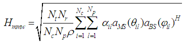 | (1) |
where,  is the complex gain of the i-th path in the l-th cluster which follows C N(0,1). For the (i,l)-th path,
  and
and  are the angles of arrival/departure(AoA/AoD), while
  and
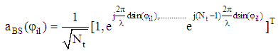
and  are the receive and transmit array response vectors at the azimuth angles of
  and
and  respectively with elevation dimension ignoring.The estimated mmWavechannel Hmmw is normalized to satisfy
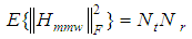 where ,
  is the Frobenius norm and the normalized mmWave channel H is obtained through multiplication of Hmmw with normalization factor
  such that
 | (2) |
 | (3) |
and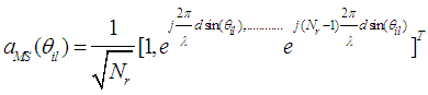 | (4) |
where,  is the signal wavelength and d is the distance between two consecutive antenna elements[4,5]
2.1. Minimum Mean Square Error (MMSE)
In Minimum mean square error (MMSE) based signal detection scheme, the MMSE weight matrix is given by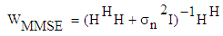 | (5) |
Where (.)H denotes the Hermitian transpose operation and the detected desired signal  from the transmitting antenna is given by [6]
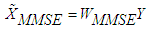 | (6) |
2.2. Best Linear Unbiased Estimation (BLUE) Based Signal Detection
In BLUE based signal detection scheme, it is assumed that the channel matrix H is deterministic and the covariance matrix Ree (=E{zzT}) of the contaminated noise is positive definite and its inversion matrix  is known or can be estimated. The noise covariance matrix Ree is of dimension 4 × 4. The estimated transmitted signal
  using such scheme can be written as [7]:
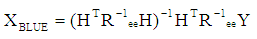 | (7) |
2.3. Zero-Forcing (ZF)
In Zero-Forcing (ZF) signal detection scheme, the ZF weight matrix is given by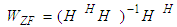 | (8) |
and the detected desired signal  from the transmitting antenna is given by
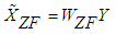 | (9) |
2.4. Q-Less QR Decomposition Scheme
With Q-less QR Decomposition scheme, the detected signal  can be found based on the least squares approximate solution as:
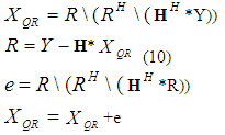 Where, Y is the received signal, R is an upper triangular matrix obtained from QR decomposition of channel matrix H [8, 9].
2.5. Turbo Channel Coding
Turbo code is systematic code with its coding rate is of ⅓ formed by concatenating in parallel two recursive systematic convolutional (RSC) codes separated by an interleaver. In such coding scheme, the encoder produces three code bits. One is the message bit treated as systematic bit and the other two are the parity bits generated by the two RSC encoders. The code may also be punctured to obtain a coding rate of 1/2. Puncturing operates only on the parity sequences; the systematic bits are not touched. In maximum a posteriori (MAP) turbo decoding, the transmitted message bits are retrieved iteratively through computation of their log likelihood ratio (LLR). Let  be a coded sequence produced by the rate ½ RSC encoder and
 be the noisy received sequence where the codeword is
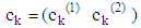 with the first bit being the message bit and the second bit being the punctured parity bit. The corresponding received word is
 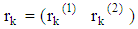 The coded bit in 0/1 format is converted to a value of +1/-1. The maximum a posterior (MAP) decoding is carried out as:
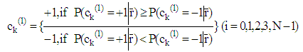 | (11) |
A posteriori log likehood ratio(LLR) of  is given by
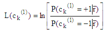 | (12) |
The MAP decoding rule in Equation (11) can be written alternatively as: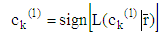 | (13) |
The magnitude LLR,  measures the likehood of
  or
or  . The LLR can be expressed as a function of the probability
  as [10]:
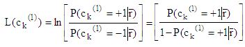 | (14) |
2.6. Repeat and Accumulate (RA)
In RA, a powerful modern error-correcting coding scheme, the extracted binary bits from the color image is rearranged into blocks with each block containing 2048 binary bits. The binary bits in each block is repeated 2 times and permuted by an interleaver of length 4096. The interleaved binary data block z is passed through a truncated rate-1 two-state Convolutional encoder whose output x is the Repeat and Accumulate encoded binary data and is given by x = zG, where G is an 4096 × 4096 matrix with 1s on and above its main diagonal and 0s elsewhere [11]. The RA encoded blocked binary data are further processed to produce a 442368× 1 single column vector data.
2.7. 2-D Median Filtering
In 2-D Median Filtering scheme, a 3×3 neighbourhood windowing mask is used for simply sorting all the pixel values within the window and finding the median value and replacing the original pixel value with the median value [12].
3. System Description
A RGB color image with 480 pixels (width) ×360 pixels (height) is processed in a MGSTC BLAST Spatial Multiplexing Scheme aided mmWave System depicted in Figure 1. The color image is converted into their respective three Red, Green and Blue components with each component is of 480 pixels ×360 pixels in size The pixel integer values [0-255] are converted into 8 bits binary form and channel coded and interleaved and digitally modulated using QAM and QPSK. The digitally modulated symbols are fed into Spatial demultiplexing section using multi-group space-time coding for production of four data series to be transmitted from antenna after executing various processing steps(Serial to parallel conversion, OFDM modulation, Cyclic prefixing and parallel to serial conversion). In receiving section, all the transmitted signals are detected with linear signal detection schemes and the detected signals are subsequently sent up to the serial–to–parallel (S/P) converter and after that they are processed with cyclic prefix removing scheme, then fed into OFDM demodulator which performs FFT operation on each OFDM block. The FFT operated OFDM block are undergone from parallel–to–serial conversion and fed into Multi-group space-time decoding section. The multiplexed complex symbols are digitally demodulated, channel decoded & filtered using 2D median diltering to recover the transmitted image.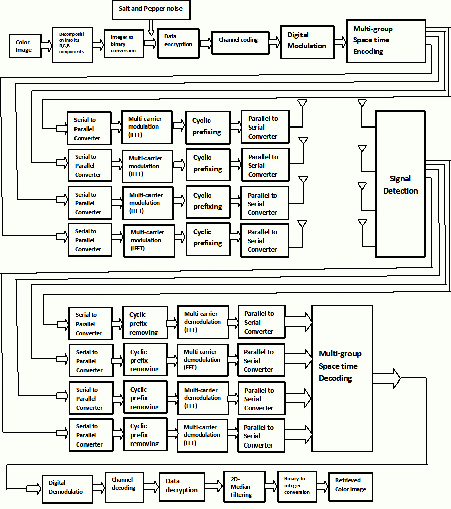 | Figure 1. Block diagram of MGSTC BLAST Spatial Multiplexing Scheme aided mmWave System |
The block diagram of the simulated MGSTC BLAST spatial multiplexing scheme aided mmWave system is shown in Figure 1. It is assumed that a single user is transmitting his/her data utilizing all allocated subcarriers during the time of several OFDM symbols and the OFDM symbols assigned are adaptively changed in the image.
4. Results and Discussion
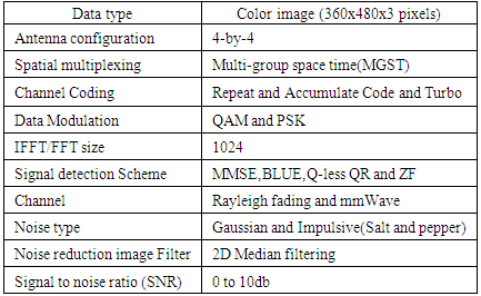
In this section, we have presented a series of simulation results to illustrate the significant impact of system performance in terms of BER in a multi-group space time encoded BLAST Spatial Multiplexing Scheme aided mmWave System with simulation parameters tabulated in Table 1.Table 1. Summary of the Simulated Model Parameters
 |
| |
|
On critical observation of graphical illustrations presented in Figure 2 through Figure 5, it is quite evident that the MGSTC BLAST Spatial Multiplexing Scheme aided mmWave System shows comparatively satisfactory performance with QAM digital modulation and Turbo coding over a lower part of SNR values where the fading channel may be treated as hostile. 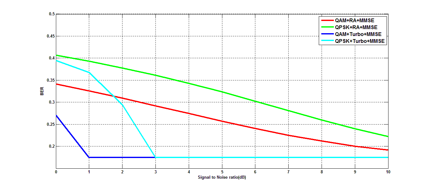 | Figure 2. BER performance of MGSTC BLAST Spatial Multiplexing Scheme aided mmWave System using MMSE signal detection technique |
In Figure 2 of MMSE implemented system, the estimated BER values for QPSK digital modulation and Repeat and Accumulate channel coding as compared to QAM digital modulation and Turbo channel coding are 0.3778 and 0.1746 for a typically assumed SNR value of 2 dB which indicates a system performance improvement of 3.35dB.In Figure 3 of ZF implemented system, the estimated BER values for QPSK digital modulation and Repeat and Accumulate channel coding as compared to QAM digital modulation and Turbo channel coding are 0.3816 and 0.1746 for a typically assumed SNR value of 2 dB which indicates a system performance improvement of 3.39dB. At 25% BER, SNR gains of 3.25, 6.75 and 9.0 dB are achieved in case of QAM with Turbo in comparison with QPSK with Turbo, QAM with RA and QPSK with RA respectively.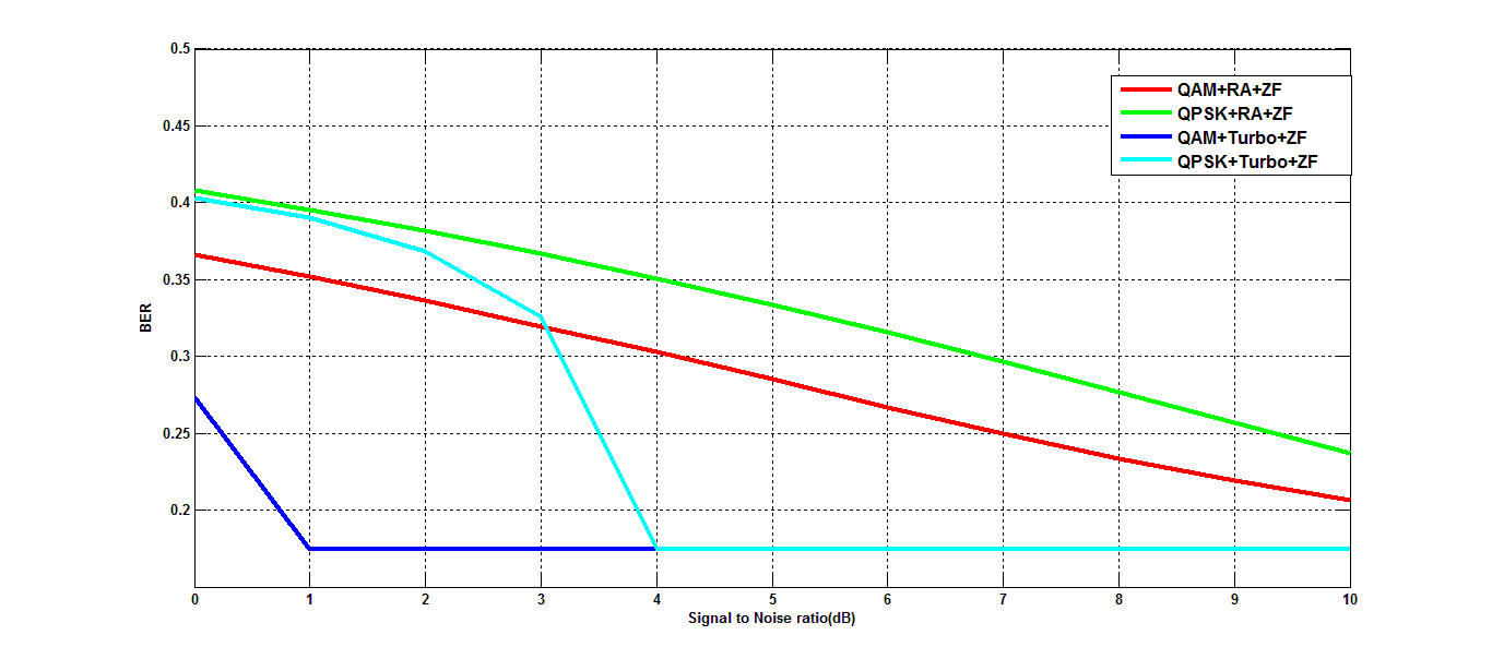 | Figure 3. BER performance of MGSTC BLAST Spatial Multiplexing Scheme aided mmWave System using ZF signal detection technique |
In Figure 4 of BLUE implemented system, the estimated BER values for QAM digital modulation and Turbo channel coding as compared to QAM digital modulation and Repeat and Accumulate channel coding are 0.4487 and 0.3706 for a typically assumed SNR value of 2 dB which indicates a system performance improvement of 0.83dB.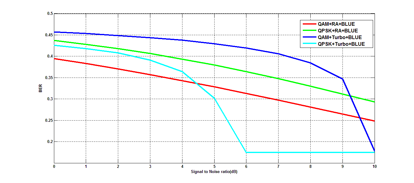 | Figure 4. BER performance of MGSTC BLAST Spatial Multiplexing Scheme aided mmWave System using BLUE signal detection technique |
In Figure 5 of Q-less QR implemented system, the estimated BER values for QAM digital modulation and Repeat and Accumulate channel coding as compared to QAM digital modulation and Turbo channel coding are 0.4074 and 0.4397 for a typically assumed SNR value of 2 dB which indicates a system performance improvement of 0.33dB.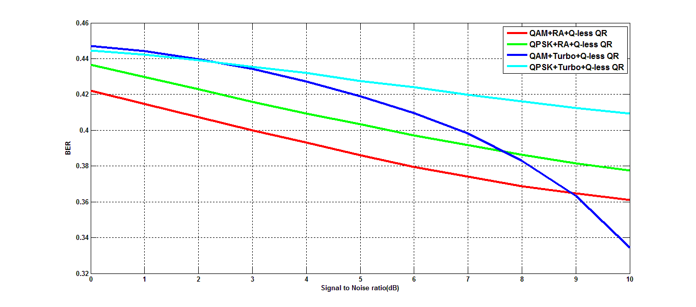 | Figure 5. BER performance of MGSTC BLAST Spatial Multiplexing Scheme aided mmWave System using Q-less QR signal detection technique |
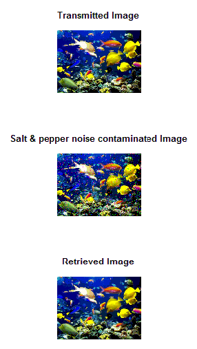 | Figure 6. Performance indicator of MGSTC BLAST Spatial Multiplexing Scheme aided mmWave System under implementation of MMSE signal detection, QAM digital modulationand Turbo channel codingfor a typical image at SNR value of 5dB |
5. Conclusions
In this paper, the performance of MGSTC BLAST Spatial Multiplexing scheme aided mmWave wireless communication system has been investigated on color image transmission using various signal detection and FEC channel encoded schemes. The results show that the implementation of MMSE signal detection scheme with Turbo channel coding and QAM digital modulation ratifies the robustness of system performance in retrieving color image transmitted over salt & pepper noise contaminated and Rayleigh fading channels. Such system can be utilized for other form of data transmission in hostile fading channels where induced noise with power is comparable with signal power.
References
| [1] | T. S. Rappaport, S. Sun, R. Mayzus, H. Zhao, Y. Azar, K. Wang, G. N. Wong, J. K. Schulz, M. K. Samimi, F. Gutierrez, 2013: Millimeter wave mobile communications for 5G cellular: It will work! IEEEAccess, vol. 1, pp. 335-349. |
| [2] | Theodore S. Rappaport Robert W. Heath Jr. Robert C. Daniels James N. Murdock, 2015: Millimeter Wave Wireless Communications, Pearson Education, Inc., USA. |
| [3] | Dan Wu, Jinlong Wang, Yuming Cai, and Mohsen Guizani, 2015: Millimeter-Wave Multimedia Communications: Challenges, Methodology, and Applications, IEEE Communications Magazine, pp.232-238. |
| [4] | Chiao-En Chen, 2015: An Iterative Hybrid Transceiver Design Algorithm for Millimeter Wave MIMO Systems, IEEE Wireless Communications Letters. |
| [5] | Ahmed Alkhateeb, Geert Leus, and Robert W. Heath Jr., 2015: Limited Feedback Hybrid Precoding for Multi-User Millimeter Wave Systems. |
| [6] | Yong Soo Cho, Jackson Kim, Won Young Yang, Chung G. Kang, "MIMO-OFDM Wireless Communications with MATLAB", John Wiley and Sons (Asia) PTE Limited, Singapore, 2010. |
| [7] | Andrzej CICHOCKI and Shun-ichiAMARI, "Adaptive Blind Signal and Image Processing Learning Algorithms and Applications", John Wiley and Sons Inc., New York, USA, 2002. |
| [8] | Yong Soo Cho, Jackson Kim, Won Young Yang, Chung G. Kang, 2010: MIMO-OFDM Wireless Communications with MATLAB, John Wiley and Sons (Asia) PTE Limited, Singapore. |
| [9] | J. J. Sadique and S. E. Ullah, “Encrypted Data Transmission in STBC Transmission Scheme Based Turbo Encoded SC- FDMA Wireless Communication System, International Journal of Applied Science and Technology (IJAST), vol. 50, (2013), pp. 1-10, Australia. |
| [10] | Yuan Jiang, 2010: A Pratical Guide to Error - Control Coding Using MATLAB, Jiang Artech House, Boston, USA. |
| [11] | Giorgio M. Vitetta, Desmond P. Taylor, Giulio Colavolpe, Fabrizio Pancaldi and Philippa A. Martin,2013: Wireless Communications Algorithmic Techniques', John Wiley and Sons Ltd, United Kingdom. |
| [12] | Oge Marques, "Practical Image and Video Processing Using MATLAB", John Wiley and Sons, New Jersey, USA, 2011. |
 Abstract
 Reference
 Full-Text PDF
 Full-text HTML