Murad Ridwan Hassen1, Mohammad Abdo1, Eduard Jorswieck2
1Dept. of Electrical & Computer Engineering, Addis Ababa University, Addis Ababa, Ethiopia
2Communication Laboratory, Dresden University of Technology, TUD, Dresden, Germany
Correspondence to: Murad Ridwan Hassen, Dept. of Electrical & Computer Engineering, Addis Ababa University, Addis Ababa, Ethiopia.
| Email: |  |
Copyright © 2014 Scientific & Academic Publishing. All Rights Reserved.
Abstract
Conventional cognitive radios exploit the licensed spectrum by opportunistically seeking the underutilized radio resource in time, frequency and geographic domains. But using smart antennas, the angle (space) spectrum can be utilized and thus leading to multiplexing of multiple users in the same channel at the same time in the same geographical area whereby leading to efficient spectrum utilization in wireless communication networks. We investigate the performance of cognitive radios equipped with smart antennas in utilizing the spatial diversity in the angle dimension in Rayleigh fading channel. As proposed, the cognitive transmitter equipped with smart antenna should keep the interference to the primary receiver below a given threshold while at the same time ensuring high enough SINRat the cognitive receiver. For a given cognitive transmitter location, the region where cognitive receivers can be deployed is determined under Rayleigh fading channel and compared with a non-fading channel.
Keywords:
Cognitive radio, Smart antenna, Angle spectrum, Rayleigh fading
Cite this paper: Murad Ridwan Hassen, Mohammad Abdo, Eduard Jorswieck, Performance of a Smart Antenna Equipped Cognitive Radio System in Rayleigh-Fading Channel, International Journal of Networks and Communications, Vol. 4 No. 1, 2014, pp. 20-27. doi: 10.5923/j.ijnc.20140401.03.
1. Introduction
The alarming growth in wireless devices and technologies coupled with the evolution to multimedia type communications has made the radio spectrum an ever scarce resource. However, surveys made by regulatory bodies in different countries on spectrum utilization have indicated that the actual licensed spectrum islargely underutilized in vast temporal and geographic dimensions [1]-[3]. Hence, innovative technologies that can offer new ways of exploiting the available spectrum are needed [4].Cognitive radio is a novel technology which improves the spectrum utilization by seeking and opportunistically utilizing radio resources in time, frequency and space domains on a real time basis [5] [6].One of the main tasks of cognitive radio system is spectrum sensing for opportunistic access of the spectrum. Conventionally, spectrum opportunity relates to the three dimensions of the spectrum space: frequency, time, and (geographic) space [4]. In the literature a number of different methods were proposed for identifying the presence of signal transmissions in these dimensions. Some of the most common methods are energy detector based sensing (e.g., [7] [8]), waveform-based sensing (e.g., [9]), cyclostationarity- based sensing (e.g., [10]), and radio identification based sensing (e.g., [11]). There are other dimensions that need to be explored further for spectrumopportunity. The angle dimension is a typical example [4]. It is to be noted that angle dimension is different than geographical space dimension. In angle dimension, a primary and a secondary user can be in the same geographical area and share the same channel. However, geographical space dimension refers to physical separation of radios in distance such as in different mobile cells. To exploit the angle opportunity, the cognitive transmitter (CT) can be equipped with smart antenna so that it directs its main lobe in the direction of the cognitive receiver (CR) while minimizing or nulling its interference in the direction of the primary receiver (PR).The authors in [12] proposed opportunistic spectrum access scheme based on angle diversity and smart antenna technology. In their proposed non-intrusive cognitive scheme they showed that, depending on the relative location of the CR and PR, interference from primary transmitter (PT) to CR can be made very small in a large area coined by them as the “decodable zone”. Consequently, the CT and PT can transmit to their respective receivers with high enough SINR when the CRs are deployed in the decodable zone. The present work is an extension of the model developed by [12] to a Rayleigh fading channel.This paper is organized as follows. The system model is presented in Section II. Section III describes the algorithm for a successful deployment of the CR in the allowable region. In Section IV, we provide some representative numerical results. Finally in Section V concluding remarks and further research topics are hinted.
2. System Model
Assume we have two wireless communication links coexisting in the same geographical region [12]. The primary users (PT and PR) are the licensed users while the secondary or cognitive users (CT and CR) are allowed to opportunistically access the primary user’s spectrum under the conditions to be outlined below. The system setup is shown in Fig. 1. The PT and CT are separated by a distance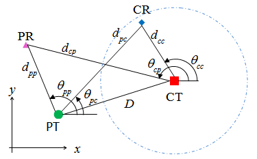 | Figure 1. Cognitive radio system with primary users |
 . The PR is randomly distributed within the circle of radius D while the CR is deployed in a small region centered on the CT at
  . Subscripts
  and
and  indicate, respectively, primary and cognitive users.
  and
and  for
for represent, respectively, the distance and azimuth angle from the i’s transmitter to the j’s receiver.To exploit the angle opportunity, the CT should be equipped with beamforming smart antenna so that it minimizes its interference to the PR while maximizing its radiation in the direction of the CR. Assume that the CT is using a 2-D uniform circular array with M arrayelements and consider, for simplicity, the azimuth angles. The array beamforming gain in the direction of the azimuth angle becomes
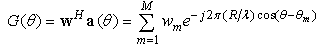 | (1) |
where  is the transmit beamforming vector,
  is the array steering vector, R is the array radius, λ is the carrier wavelength and
  is the angular location of the array elements with respect to the horizontal axis.The instantaneous signal-to-interference-plus noise ratio (SINR) at the PR and CR, respectively, are
 | (2) |
 | (3) |
where  is the instantaneous received power at receiver j that was transmitted by the ith source
  and
and  are, respectively, the primary and cognitive transmit beamforming gains.
2.1. Rayleigh Fading Channel
In a Rayleigh fading channel, the received power is exponentially distributed. Let  be the average received power (including path loss and shadowing) at receiver j that was transmitted by the ith source. Then
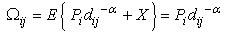 | (4) |
where  is the expectation operator,
  is the power transmitted by source
  is the path loss factor and
  is the large-scale shadowing power with zero mean. The probability density function (pdf) of the instantaneous power
  is
is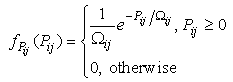 | (5) |
Thus, the SINRs (2) and (3) are random variables of the form | (6) |
where X and Y are exponentially distributed independent random variables and  are real numbers.
2.2. Distribution of SINR
As shown above, the SINR is expressed as a ratio of two random variables. The distribution of the ratio of two random variables has been extensively investigated by many authors especially when X and Y are independent and identically distributed (i.i.d.) random variables [13, 14].To determine the pdf of (6), define an auxiliary random variable | (7) |
The joint distribution of Z and W becomes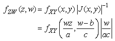 where
where  is the Jacobian of the transformation. We assume
  and
and  to be i.i.d. exponential random variables with mean
  and
and  .Hence, integrating over W, the marginal pdf of Z becomes
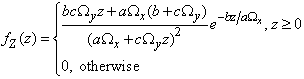 | (8) |
The mean of Z becomes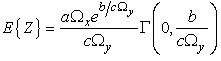 | (9) |
where 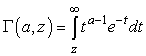 is the incomplete gamma function.The probability of
  becomes
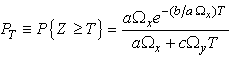 | (10) |
3. Problem Statement
Consider a scenario where all users except the CT use omnidirectional antennas. For communication of cognitive radio systems to be established, the CT equipped with beamforming smart antenna has to guarantee that its average interference to the PR is below a threshold Io while at the same time keeping high enough SINRc at the CR. The cognitive radio has to be aware of the approximate location of the PR. Assume that the distance to the PR,  , is known exactly while its angle information
  is uncertain by
  . Let
. Let  be the worst interference gain in the direction of PR, then
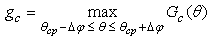 | (11) |
The optimal CT beamforming can be optimized as: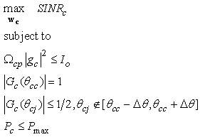 | (12) |
where 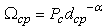 , -the first constraint, guarantees that the worst interference to the PR has to be kept below Io,
  is a constraint on the sidelobe leakage of the CT antenna beam with half-power beamwidth
  ,
, is the maximum transmission power of CT,
  , where
  is the average SNR requirement of the CR.From the optimization problem (12),
  is determined. Note that when
  the gain becomes
  After determining the optimal
  for the CT, the CT’s transmission power becomes
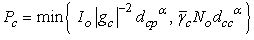 | (13) |
The first term in (13) comes from the interference constraint 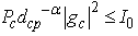 while the second term is
 For successful communication of the cognitive system, the SINRc at the CR has to be greater than a minimum value T with a high probabilityp. PT in (10) for the CR with
  , and referring to (3) and (6), we have
  ,
, 
 and
and  so that
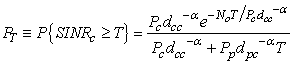 | (14) |
To meet the power constraint (13), 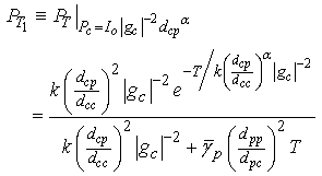 | (15) |
 | (16) |
where 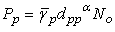 and
and  . Therefore,
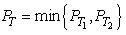 | (17) |
The CT, subject to (12) and (17), can establish communication with the CR at high probability p when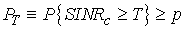 | (18) |
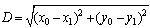
For a fixed CT location, the area in space where (18) is satisfied defines the region where the CRs can be deployed to have permissible communication.If only large-scalepath loss (non-fading channel) is considered, communication is established when with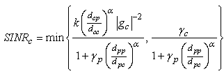 | (19) |
4. Numerical Results
Assume location of the PR is fixed so that dpp, dcp, and θcp are fixed. The CR is to be randomly deployed with dcc and θcc uniformly distributed, i.e.,  and
and  Further assumedmin=10m, dmax=D,
  the path loss factor to be
  and
and  The allowable region where the CR can be deployed is simulated using the Monte-Carlo simulation for different combinations of
  Tandp.For
 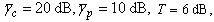 and
and  the allowable region, both for non-fading and Rayleigh fading channels, is shown in Fig. 2. The second simulation, shown in Fig. 3, is obtained as in above except that
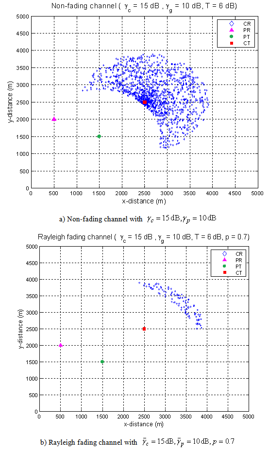
  Fig. 4 shows the effect of varying p.
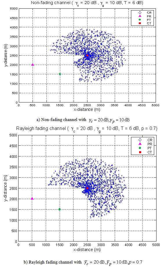 | Figure 2. Comparison of non-fading and Rayleigh channels for  |
 | Figure 3. Comparison of non-fading and Rayleigh channels for  |
 | Figure 4. Effect of varying p in Rayleigh fading channel |
Define the angle spectral efficiency  as
as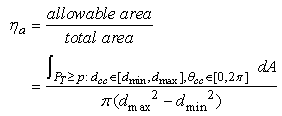 | (20) |
Thus  represents the improvement on angle spectral usage. Spectral efficiency of 80.89% and 71.80% is achieved in simulations shown in Fig. 2(a) and 2(b), respectively. We observe that the angle spectral efficiency decreases in a Rayleigh fading channel as compared to a non-fading channel with the same
  as expected. Similarly 64.27% and 10.38% is achieved as shown in Fig. 3(a) and 3(b), respectively, while 34.22% and 2.0% is achieved in Fig. 4(a) and 4(b), respectively.Fig. 5 shows variation of
  as a function of
  for non-fading channel and Rayleigh fading for different p. From the figure, we infer that the efficiency jumps from zero to approximately 70% in almost 5 dB
  interval and then saturates.
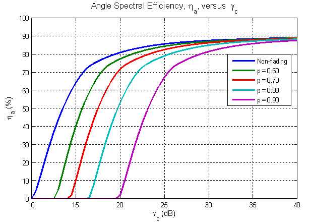 | Figure 5. Angle spectral efficiency,  as a function of as a function of  |
5. Conclusions
In this paper we have shown that the angle spectrum in cognitive radio system can be greatly exploited using smart antenna and thus leading to multiplexing of multiple users in the same channel at the same time in the same geographical area. The resulting efficiency in spectrum utilization greatly relieves the already congested radio spectrum. The region where the CRs are to be deployed for a given PT, PR and CT locations is determined for Rayleigh fading channel and compared with the non-fading channel. The angle spectral efficiency for Rayleigh channel is lower as compared to a non-fading channel with the same power levels and radio terminal locations. We have also shown that increasing the CT power beyond a certain level has negligible effect on the spectral efficiency.Future work might include other types of fading channels. Fast fading and frequency selective Rayleigh channels can also be considered.
References
| [1] | FCC, “Spectrum Policy Task Force, ET Docket 02-135,” Nov. 2002. |
| [2] | QinetiQ Proprietary, “Cognitive Radio Technology - A Study for Ofcom,” Feb. 2007. |
| [3] | Khaled Ben Letaief and Wei Zhang, “Cooperative Communications for Cognitive Radio Networks,” IEEE Proc., Vol. 97, No. 5, May 2009. |
| [4] | Tevfik Yücek and Hüseyin Arslan, “A Survey of Spectrum Sensing Algorithms for Cognitive Radio Applications,” IEEE Communications Surveys& Tutorials, vol. 11, no. 1, first quarter 2009. |
| [5] | I. Mitola, J. and J. Maguire, G. Q., “Cognitive radio: making software radios more personal,” IEEE Personal Commun. Mag., vol. 6, no. 4, pp. 1318, Aug. 1999. |
| [6] | S. Haykin, “Cognitive radio: Brain-empowered wireless communications,” IEEE J. Sel. Areas Commun., vol 23, pp. 201-220, Feb. 2005. |
| [7] | D. Cabric, A. Tkachenko, and R. Brodersen, “Spectrum sensing measurements of pilot, energy, and collaborative detection,” in Proc. IEEEMilitary Commun. Conf., Washington, D.C., USA, Oct. 2006, pp. 1-7. |
| [8] | F. Digham, M. Alouini, and M. Simon, “On the energy detection of unknown signals over fading channels,” in Proc. IEEE Int. Conf. Commun.,vol. 5, Seattle, Washington, USA, May 2003, pp. 3575-3579 |
| [9] | H. Tang, “Some physical layer issues of wide-band cognitive radio systems,” in Proc. IEEE Int. Symposium on New Frontiers in Dynamic SpectrumAccess Networks, Baltimore, Maryland, USA, Nov. 2005, pp. 151-159. |
| [10] | K. Kim, I. A. Akbar, K. K. Bae, J.-S. Um, C. M. Spooner, and J. H.Reed, “Cyclostationary approaches to signal detection and classificationin cognitive radio,” in Proc. IEEE Int. Symposium on New Frontiers inDynamic Spectrum Access Networks, Dublin, Ireland, Apr. 2007, pp.212-215. |
| [11] | M. Gandetto and C. Regazzoni, “Spectrum sensing: A distributed approach for cognitive terminals,” IEEE J. Select. Areas Commun., vol. 25, no. 3, pp. 546-557, Apr. 2007. |
| [12] | Senhu Huang, Zhi Ding, and Xin Liu, “Non-intrusive cognitive radio networks based on smart antenna technology,” in Proc. IEEE GLOBECOM 2007, pp. 4862–4867. |
| [13] | Marsaglia, G., “Ratios of normal variables,” Journal of Statistical Software, 16(4), pp. 1-10, 2006. |
| [14] | N. B. Khoolenjani, K. Khorshidian, “On the Ratio of Rice Random Variables,” JIRSS vol. 8, Nos. 1-2, pp 61-71, 2009. |
 Abstract
 Reference
 Full-Text PDF
 Full-text HTML