-
Paper Information
- Paper Submission
-
Journal Information
- About This Journal
- Editorial Board
- Current Issue
- Archive
- Author Guidelines
- Contact Us
International Journal of Networks and Communications
p-ISSN: 2168-4936 e-ISSN: 2168-4944
2013; 3(3): 91-98
doi:10.5923/j.ijnc.20130303.03
PAPR Reduction in MIMO-OFDM Systems Using PTS Method
 Abstract
 Reference
 Full-Text PDF
 Full-text HTML
A. Bensaad , Z. Bensaad , B. Soudini , A. Beloufa
Applied Materials Laboratory, Centre de Recherches (ex-CFTE), University of Sidi Bel Abbès, 22000 Sidi Bel Abbès, Algeria
Correspondence to: A. Bensaad , Applied Materials Laboratory, Centre de Recherches (ex-CFTE), University of Sidi Bel Abbès, 22000 Sidi Bel Abbès, Algeria.
| Email: |  |
Copyright © 2012 Scientific & Academic Publishing. All Rights Reserved.
Abtract Multiple-Input Multiple-Output Orthogonal Frequency Division Multiplexing (MIMO-OFDM) is an attractive method which has gained significant interests as a promising candidate for the 4th Generation wireless communication. However, one of the main disadvantages of MIMO-OFDM is its high peak to average power ratio (PAPR). In this paper, Partial Transmit Sequences (PTS) method introduced in the MIMO-OFDM system is presented with various simulation results to verify its effectiveness. Results shows that PTS technique improves the performance of the MIMO-OFDM system, moreover, it can be shown that with increasing the value of the number of non overlapping sub-blocks, the PAPR performance becomes better. Different kinds of PTS schemes are also plotted. The Pseudo-random seems leading the better performance.
Keywords: MIMO-OFDM, Single-Input Single-Output (SISO-OFDM), peak-to-average power ratio (PAPR), Partial Transmit Sequences (PTS), Complementary cumulative distribution function (CCDF)
Cite this paper: A. Bensaad , Z. Bensaad , B. Soudini , A. Beloufa , PAPR Reduction in MIMO-OFDM Systems Using PTS Method, International Journal of Networks and Communications, Vol. 3 No. 3, 2013, pp. 91-98. doi: 10.5923/j.ijnc.20130303.03.
Article Outline
1. Introduction
- The Multi-input multi-output orthogonal frequency- division multiplexing frequency-division multiplexing (MIMO-OFDM) has gained significant interests as a promising candidate for the 4th Generation (4G) wireless communication. It combines the capacity and diversity gain of MIMO systems with the equalization simplicity of Orthogonal Frequency Division Multiplexing (OFDM) modulation. A higher capacity with high bandwidth efficiency can be achieved over broadband multipath fading wireless channels[1, 2]. MIMO systems uses multiple transmit and receive antennas to improve link reliability and data rates. Link reliability is obtained through transmit and receive diversity, and leads to improved coverage[3]. High data rates multiplexing[4]) is obtained through spatial multiplexing, where independent data streams are transmitted in parallel over different transmit antennas. OFDM has been recently established for several systems such as American IEEE802.11, the European equivalent HiperLan/2, digital video and audio broadcasting. OFDM is a multicarrier transmission technique, which divides the available spectrum into many carriers, each one being modulated by a low data rate stream. OFDM has many advantages which make it an attractive scheme forhigh-speed transmission links such as robustness in frequency frequency selective fading channels, high spectral efficiency, capability of handling multipath fading effects, and relatively simple receiver implementation. However, it suffers from high peak-to-average power ratio (PAPR) which causes severe nonlinear distortion in actual devices such as power amplifiers. These large peaks cause saturation in the power amplifiers, leading to inter-modulation products among the subcarriers and disturbing out of band energy[5]. MIMO-OFDM, like a single-input single output SISO-OFDM, has the drawback of its high PAPR. Thus, a high dynamic range amplifier is needed, which increases the cost of the system and reduces the power efficiency.Several techniques have been proposed in order to reduce the PAPR. Some of these techniques are based on phase rotation and need Side Information (SI) to be transmitted to the receiver such as Partial Transmit Sequence (PTS)[6, 7, 8] and Selected Mapping (SLM)[8, 9, 10]. Some others do not need side information such as clipping and filtering[11, 12, 13], tone reservation[14, 15], block coding[16], and ACE [17]. In[8], authors have derived a simplified maximum likelihood (ML) decoder for SLM and PTS techniques that operates without side information to reduce the PAPR in orthogonal frequency-division multiplexing (OFDM). In this paper, we analyze the combination of PTS method with MIMO-OFDM systems. For the proposed scheme, the PTS method is applied to each single transmit antenna. Based on the CCDF distribution of the MIMO-OFDM systems, the optimal parameters are chosen to have the lowest PAPR for each transmit antennas. The rest of the paper is organised as follows: In section II, the OFDM system model, PAPR and CCDF distribution are presented. In section III, the PTS method for OFDM system is investigated. In section IV, the MIMO-OFDM system model based on PTS method is given. Simulation and results are described in section V and Section VI concludes the paper.
2. Papr in OFDM System
2.1. OFDM System Model
- A block diagram of OFDM system is depicted in Fig. 1. The OFDM signal consists of a sum of subcarriers that are modulated by phase shift keying (
 ) or Quadrature Amplitude
  signals. First, the serial input data stream is arranged into
  groups of bits, where
  is the number of subcarriers. The number of bits in each of the
  groups determines the constellation size for that particular subcarrier. The mapped complex symbols are then serial-to-parallel (S/P) converted and oversampled by a factor L resulting in a block of
  complex symbols.
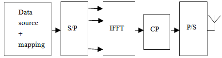 | Figure 1. Block diagram of OFDM system |
 zero-padding in the middle of the original input vector to produce accurate PAPR estimates. The discrete time domain OFDM signal oversampled by a factor of
  can be obtained by
  -points
  as:
as: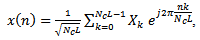 | (1) |
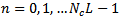 With,
With,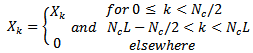 | (2) |
 denote the number of subcarriers or
  size and
  is the complex symbol carried over a subcarrier k, respectively. The
  subcarriers chosen to transmit the signals are mutual orthogonal one to each other and each of them is located at
  , is the frequency spacing between adjacent subcarriers,
  is the OFDM data symbol period and
  is the oversampling factor. The resulting vector is then appended with a cyclic prefix (
 ) of length
  , which is the copy of the last
  elements of the
  output block. The
  acts like a guard interval between successive symbols and prevents Intersymbol Interference
  if the channel impulse response length is less or equal to the length of the
  . In the receiver, the whole process is reversed to recover the transmitted data.
2.2. Peak to Average Power Ratio (PAPR)
- The PAPR of OFDM signal sequence is defined as the ratio between the maximum instantaneous power and its average power, which can be written for the oversampled OFDM signal symbol as[18, 19, 20]:
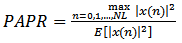 | (3) |
 is the expectation operator and
 is the average power.The above power characteristics can also be described in terms of their magnitudes (not power) by defining the crest factor (CF) as:
  | (4) |
2.3. Complementary 
- The Complementary Cumulative Distribution function (
 ) is used to measure the probability that the PAPR of a certain data block exceeds a certain threshold
  The
The  of the PAPR of the data block is desired to compare outputs of various reduction techniques. It is defined with Nyquist rate sampling as:
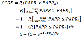 | (5) |
 denote the crest factor. This expression is derived under the assumption that the N samples are mutually independent and it is not accurate for a small number of subcarriers. Therefore, the above equation does not hold for oversampled signals case, the following simplified CDF will be used[21, 22]:
 | (6) |
 has to be determined by fitting the theoretical CDF into the actual one. It has been shown that
  is a good approximation for the oversampled OFDM signals in general.
3. Partial Transmit Signals PTS
- Partial Transmit Sequences (PTS) generates a signal with a low PAPR through the addition of appropriately phase rotated signal parts. Fig. 2 shows the block diagram of the partial transmit sequence (PTS) technique. The signal
 to be transmitted is partitioned into disjoint sub-blocks Xv, of length
  which is represented by the vector
  as[23, 24]:
 | (7) |
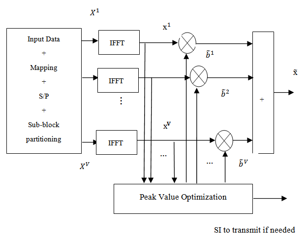 | Figure 2. The Block diagram of PTS Technique |
 is the number of subcarriers and V is the number of sub-blocks. Complex phase factors,
  | (8) |
 | (9) |
 | (10) |
 | (11) |
 admissible angles,
  then the required number of bits for side information is
 bits per OFDM symbol. The computational complexity of PTS method depends on the number of phase rotation factors allowed. The selection of the phase factors
  is limited to
  set of elements number to reduce the search complexity[27]. The sets of phase factors should be searched to find the optimum set of phase vectors. Furthermore, the search complexity increases exponentially with the number of sub-blocks and also depends on the sub-block partitioning. It was shown in[28, 29], that the optimal combination of phase factors with a modified discrete PSO method’s can achieve better performance with low search complexity and hence achieve the OFDM signals with low PAPR. In fact, there are three different kinds of the sub-block partitioning schemes: adjacent, interleaved, and pseudo-random. In the adjacent partition, the data sequence is divided into
  sub-blocks, for each one, it contains
  consecutive subcarriers, for the pseudo-random partition, each subcarrier can be randomly assigned to any position of the sub-block with the length
  ; Interleaved partition also segments the sequence into
  sub-blocks but within each of them, subcarriers are allocated in a space of
  . The common point of these three different partition schemes is that each subcarrier is only been assigned once, and the length of each sub-sequence is same.
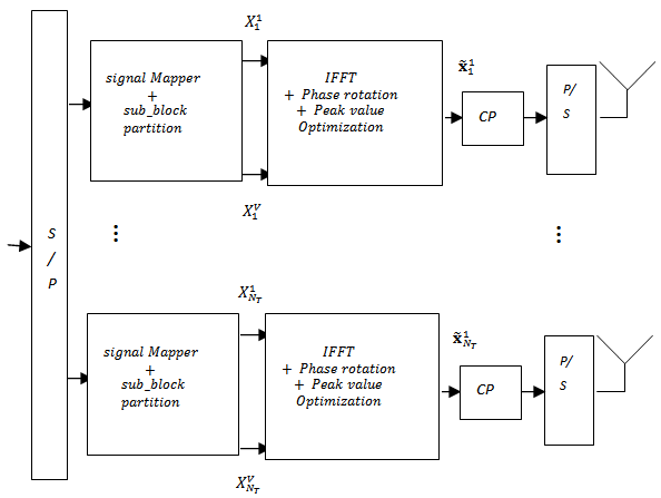 | Figure 3. Block diagram of PTS-MIMO-OFDM |
4. MIMO-OFDM System
- Fig. 3 shows the proposed block diagram of MIMO-OFDM system using PTS technique. The PTS-OFDM technique is applied to each transmit antenna. Following the procedure described in the section III, the data sequence with
 subcarriers to be transmitted is partitioned into
  non-overlapping sub-blocks which are represented by the vectors
 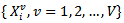 for the
  sub-block partition at the
  transmit antenna. Then, the vector can be written as:
  | (12) |
 or 0,
or 0,  and each sub-block vectors has the same size
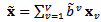
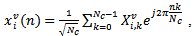
  .Each partitioned sub-blocks are converted from the frequency domain to time domain using the N-point IFFT (assuming oversampling factor
  ). The discrete time domain representation of the vth sub-block is given by:
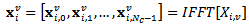 | (13) |
 | (14) |
 Then, the time domain sequences are combined with weighting factors,
 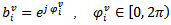 and
and 
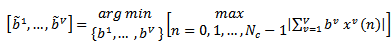
 used for the phase rotation. The binary phase factors of {+1, -1} can be used to reduce the system complexity while searching for the optimum set of phase vector.To avoid in and out of band distortions due to non linear power amplification, PAPR of all transmit signals should be simultaneously as small as possible. Since performance is governed by the worst-case PAPR, we define MIMO-OFDM as the maximum of all PAPR related to all NT MIMO paths. Subsequently, the CCDF of the PAPR of the MIMO-OFDM signals at each
  transmit antenna is given by[30, 31, 32]:
 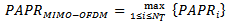 | (15) |
 corresponds to the PAPR at the
  transmit antenna. This can be written as:
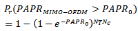 | (16) |
5. Simulation Results
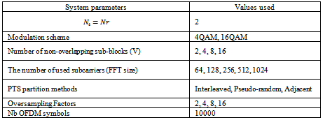
- Our simulation is based on the following system parameters shown in table 1. The number of subcarriers is chosen in the range of
 to 1024 and is equal to the FFT size. The number of block OFDM symbols was equal to 10e+4 symbols transmitted over
  antennas and received by the same number of antennas.
|
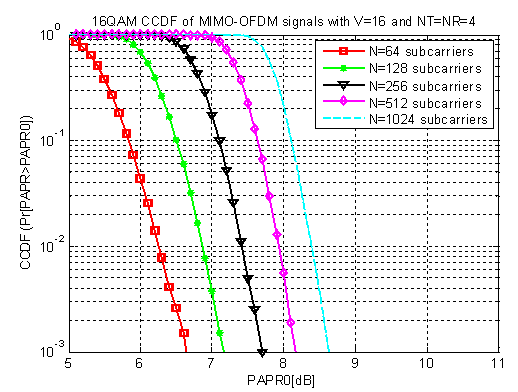 | Figure 4. PAPR reduction using PTS method for MIMO-OFDM system with different number of subcarriers, NT=NR=4 and V=4 |
 | Figure 5. PAPR reduction with different PTS sub-blocks for MIMO-OFDM and SISO-OFDM system |
 | Figure 6. Comparison of PAPR reduction performance for different sub-block partitioning schemes, Oversampling factor=4 and V=4 |
 | Figure 7. PAPR reduction using PTS method for MIMO-OFDM with N=128, Nos=4 and V=4 |
 | Figure 8. Comparisons of PAPR reduction performance with different number of transmit antennas |
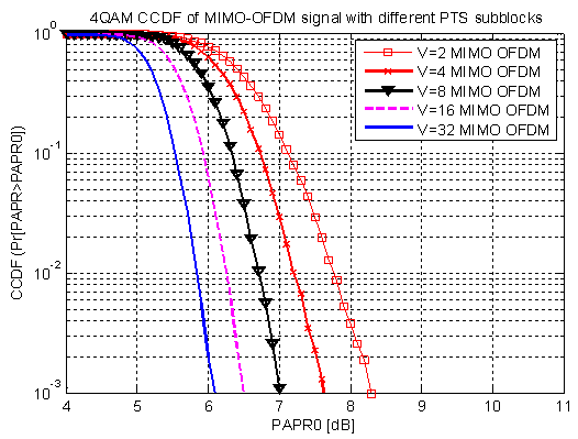
 .In Fig. 5, the CCDF of MIMO-OFDM signal using PTS method is plotted as a function of PAPR distribution. The number of sub-blocks changes from 2 to 16 for 16QAM modulation scheme and 128 subcarriers.It can be seen that performance of the combined PTS-MIMO-OFDM improves as the number of sub-blocks increases with V =2, 4, 8, 16 and 32. In Fig. 5, when CCDF is equal to ‘
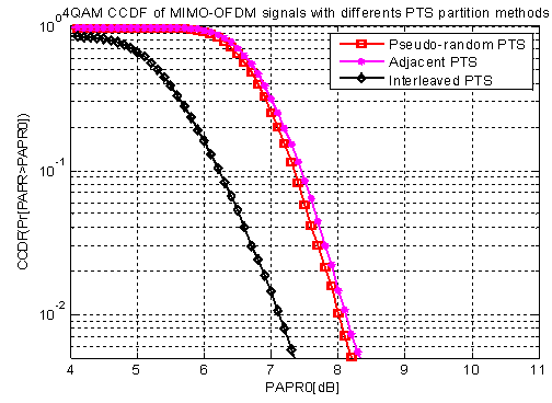
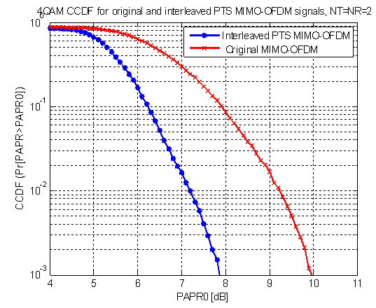
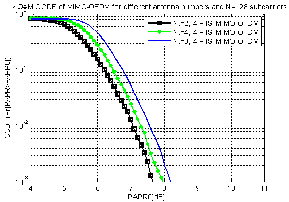
 ’, the PAPR is reduced by about 0.5 dB, while the sub-block size is increased from 4 to 8, and 0.5 dB form 16 to 32, respectively. It makes the phase factors always follow the best phase factors, hence achieve the OFDM signals with low PAPR.Fig. 6 shows the CCDF of MIMO-OFDM signal as a function of PAPR distribution when using different PTS sub-blocks partitioning schemes: adjacent, interleaved and pseudo-random. The number of sub-blocks is fixed to 4 and the number of subcarriers is chosen equal to 128. The number of transmit and received antennas is chosen equal to 2. As we can see, the CCDF performance is affected by the choice of the partitioning method. Interleaved method leads to a better performance for PAPR’s than the two others methods.For the sake of comparison, the CCDF’s of the MIMO-OFDM system was plotted with and without PTs method. As shown in Fig. 7, the later outperforms the original one. In Fig. 8, the CCDF of MIMO-OFDM system is plotted for V=4 Interleaved PTS and different transmitted antenna numbers 2, 4 and 8. The 4QAM is used for constellation mapping and the oversampling factor is set equal to 4. The CCDF performance is better when the number of antennas used is kept small. The system sum all the symbol subcarriers from all transmit antennas which increase the possibility of having high amplitude signals.
6. Conclusions
- MIMO-OFDM is a very attractive technique for the 4th wireless communications. It combines the capacity and diversity gain of MIMO systems with the equalization simplicity of Orthogonal Frequency Division Multiplexing (OFDM) modulation. However, like a single-input single output SISO-OFDM, it has the drawback of its high PAPR. Thus, a high dynamic range amplifier is needed, which increases the cost of the system and reduces the power efficiency. In this paper, PAPR reduction in MIMO-OFDM systems using PTS method is investigated. Results show that PTS technique improves the performance of the MIMO-OFDM system. It should be noted that the data can be divided into a number of non overlapping sub-blocks in different structures. PTS sub-block with pseudo random having the best performance and interleaving having the worst. It makes the phase factors always follow the best phase factors, hence achieve the OFDM signals with low PAPR.