-
Paper Information
- Next Paper
- Previous Paper
- Paper Submission
-
Journal Information
- About This Journal
- Editorial Board
- Current Issue
- Archive
- Author Guidelines
- Contact Us
International Journal of Networks and Communications
p-ISSN: 2168-4936 e-ISSN: 2168-4944
2013; 3(1): 12-20
doi:10.5923/j.ijnc.20130301.02
Design and Development of Communication and Control Platform for Medical Tele-diagnosis Robot (MTR)
 Abstract
 Reference
 Full-Text PDF
 Full-text HTML
Muralindran Mariappan , Brendan Khoo
Robotics and Intelligent Systems(myRIS) Research Group, AiRU, University Malaysia Sabah, Kota Kinabalu, 88400, Malaysia
Correspondence to: Muralindran Mariappan , Robotics and Intelligent Systems(myRIS) Research Group, AiRU, University Malaysia Sabah, Kota Kinabalu, 88400, Malaysia.
| Email: |  |
Copyright © 2012 Scientific & Academic Publishing. All Rights Reserved.
Medical emergencies are happening everyday around the world with varying severity ranging from a common road accident to a distress wounded soldier. The absence of a qualified specialist in hospitals especially in developing countries often leads to misdiagnosis which can be fatal or causing further deterioration to the patient’s condition. This often solved by incorporating mobile tele-presence robots into hospitals however the exorbitant cost in maintaining and setting up the system has prevented the developing countries from using them. Medical Tele-diagnosis Robot (MTR) is developed to provide a cost efficient alternative for the developing countries. MTR is a mobile medical tele-diagnosis robot which allows physicians to communicate with the patients, virtually present to give direction in a medical procedure, to diagnose patients and to round at the patients’ ward. This research has contributed in the development of a doctor-robot interface where the doctor or user can control the robot reliably via regular internet connection from a different location, a distributed secured network for MTR’s communication, anaudio-visual communication system for tele-diagnosis and a medical data management system. The overall setup and maintenance cost of MTR is reduced by adopting a decentralized network via hybrid P2P technology. With this, the network load is distributed among the users. As for the audiovisual system, the timeliness of the video transmission from the robot to the operator can be attained by CUDA H.264 video encoding to reduce the size of the video stream and by taking advantage of the highly-parallel processors in the graphics processing unit. Medical data management system, provides a decentralized data storage and sharing system to reduce network and server cost. The complete system is tested with a series of experiments to observe its performance and behavior.
Keywords: Medical Tele-diagnosis Robot (MTR), Tele-Presence Robot, P2P Tele-Diagnosis
Cite this paper: Muralindran Mariappan , Brendan Khoo , Design and Development of Communication and Control Platform for Medical Tele-diagnosis Robot (MTR), International Journal of Networks and Communications, Vol. 3 No. 1, 2013, pp. 12-20. doi: 10.5923/j.ijnc.20130301.02.
Article Outline
1. Introduction
- Robots have unsurpassed contributions in our daily life. They have helped in many dangerous missions like exploring a level 7 nuclear power plant disaster in Fukushima Dai-ichi[1] and scouting for insurgents from the sky in Iraq[2,3], in hard to reach areas like urban gas pipelines[4] and also in mundane tasks like surface polishing[5]. In medicine, robots were given important roles as early as 1960 but faced with many challenges due to issues like safety, precision and cost[6]; even so robots have been part of many medical and healthcare areas: surgery, rehabilitation, human body research, replacing lost body functions, personal care and health promotion[7].The accommodation of robotic and ICT systems in medical and healthcare discipline is due to several reasons like lack of medical personnel due to large aging population, better diagnostic capabilities, lower cost and improved overall quality. Medical robots currently in service are surgical robots[8,9], tele-presence robots[10] and rehabilitation robots[11]. Besides that, robots have also been developed for assisting in radiotherapy[12,13], rehabilitation therapy[14], as well as dispensing drugs[15] in medical centers. Surgical robots are developed to assist surgeons in different medical procedures, such as laparoscopic surgery[16], orthopedic surgery[17], neurosurgery[18], and tele-surgery[19]. The use of these robots has helped to improve precision, reduce incision size, quicken healing time and minimize blood loss, thus patients will experience less post-operative pain, smaller scar and shorter hospital stay[20]. The other type of health care robot widely used in medical field is tele-presence robot. These robots allow doctors to perform monitoring, consultation and rounding remotely to different locations without the need for transportation.Remote presence, tele-presence, distant presence, virtual presence and surrogate presence are the common terms for an infrastructure capable of representing or act in behalf of others from a distance[21]. Robotic tele-presence as described by[10] provides the perception of being there or “virtually there” by allowing the users to see, talk, hear and interact thru audiovisual communication on a robotic omnidirectional mobile base. These robots are deployed in places such as museum, trade fairs, office buildings, hospitals and department stores[22]. When these similar technologies are deployed in a medical centers, it can offer healthcare to secluded areas, reduce cost by eliminating the need for transportation and provide aid in solving problems related to patient care in densely populated centers[23]. This is essentially needed by developing countries to overcome the lack of medical experts. InTouch Health’s RP-7 is a common example of commercialized medical tele-presence robot used in developed countries like United States[10]. Unlike regular tele-presence robots, it has medical functionalities and able to interface with peripheral medical instruments. However, these systems are too costly for many under-developing nations due to their exorbitant purchase and maintenance cost[24].Emergency cases such as orthopedic emergency cover about 40% of the cases in Accident and Emergency Department of a hospital. Often these cases are hard to diagnose and handle without the help of a qualified specialist[25]. Consultations with other experts may be needed depending on the experience, the expertise and the confidence of the doctor in charge of the case. In addition, the personnel present at that instance may not qualify in managing that particular case. These may lead to life-threatening complications if proper and immediate treatments are not accessible. E-health systems like EMOSNet[26] and TeleOrthPaedics[25] are useful to provide adequate preparation time for the surgical unit before the arrival of the patient and reduce the possibility of sending patient to the wrong medical center due to insufficient case information.However, the existing e-health systems including EMOSNet and TeleOrthPaedics do not have robotic tele-presence capability, which gives the doctors real-time interaction with their patients. Besides being too pricey for developing countries, current robotic tele-presence systems such as RP-7[10] are only designed for tele-rounding purpose rather than attending patients in emergency situations. Therefore, a specialized robotic system with flexible vision system for diagnosis and medical instruments to obtain vital signs of the patient is developed specifically for emergency and rounding routines. Medical Tele-diagnosis Robot or MTR is a mobile robot equipped with basic medical instruments, including sphygmomanometer, Pulse Oximeter, Vascular Doppler and X-ray scanner for real-time diagnosis. It is also fitted with two video cameras: diagnosis camera and navigation camera. The diagnosis camera is oriented and positioned with the help of a flexible robotic arm.The structure, requirement and functionality of MTR introduce new challenges to the design of its communication and control platform. First, a specialized network mechanism must be designed to operate on low capacity networks to make the system affordable for developing countries. This is because high capacity network translates to high maintenance and high setup costs. Second, a specialized video encoding and decoding module must be developed to encode two real-time medical video streams as these functions require significant computation and network resources. Third, a simple and low cost robot to network interface must be developed to provide network access to the robot.
2. The System
- The system proposed by this research intends to work with Medical Tele-diagnosis Robot (MTR) equipped with basic medical instruments to allow specialists or doctors diagnose patients remotely via regular broadband internet(Figure 1). In addition, this robot is also equipped with a non-interventional flexible robotic arm to position and orientate the diagnosis camera (a high-resolution video camera). This feature is especially useful for diagnosing patients in cases similar to orthopedic emergencies. The robot has a holonomic mobile base as a means of locomotion. The holonomic drive gives the robot an easier maneuvering. Also, the platform developed by this research must interface with the robot controller boards to control the robotic actuators and obtain readings from the onboard sensors located around the robot.The development of the system described by this research is separated into network engine, audio-visualsystem, robot-computer interfacing, medical information management and robot control interface.
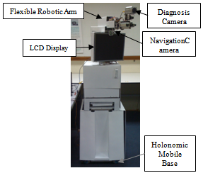 | Figure 1. Medical Tele-diagnosis Robot |
2.1. MTR Network
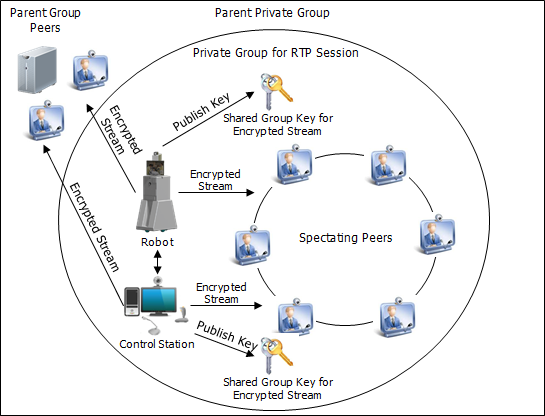
- MTR Network incorporates P2P overlay technology to create a unique self-scaling architecture where an increase of participation increases the capacity of the system, thus it is capable of providing certain types of services at a cost level unachievable by client/server architectures[27] especially on services that need extensive network bandwidth, storage and computation. This is done by sharing the cost of operating the overlay with every end user hence lowering down the hardware and network investment needed to launch the infrastructure.P2P overlay may sound perfect and attractive theoretically, however the lack of security features in pure P2P networks is making them vulnerable to security attacks that are meant to disrupt, intercept and corrupt the functions of their systems. Pure P2P network is also extremely dependent on peer behaviors (churn-rate, the ratio of contribution/consumption and rogue peers), which influence the quality of the infrastructure. To overcome the downside of a common P2P overlay, MTR Network uses hybrid P2P network which incorporates both centralized and decentralized architecture. This architecture provides peer access control on the overlay thru central servers. With these servers, the network is capable of granting and revoking access permission of each peer. Besides that, local dedicated servers are incorporated into P2P groups to store and host files consistently even when no seeding peer available.
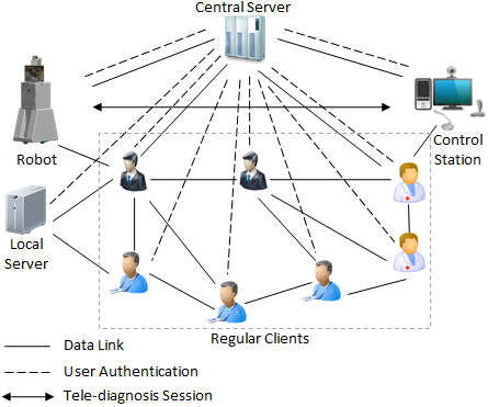 | Figure 2. MTR network |
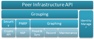 | Figure 3. Windows Peer Infrastructure |
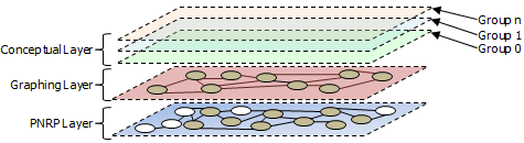 | Figure 4. Layers in MTR Network |
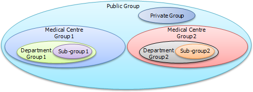 | Figure 5. Visualization of MTR Network Overlay in conceptual layer |
2.2. Audio-visual System
- Audiovisual System plays a very important role in MTR because it handles the core functionality of the system – visual (video) and audio (voice) communication for doctors, patients and nurses in (1) diagnosis, (2) discussion and exchanging of ideas between medical personnel and (3) coordinating a medical procedure. For this, it is very important to assure that the proposed system for this research suits the application and needs.Firstly, MTR requires two different cameras to operate at the same time during a tele-presence (tele-diagnosis) session because it requires complex positioning of camera to capture an accurate image on the region of interest. For this, a high-resolution camera is mounted on a multi-degree-of-freedom robotic arm to position and orientate the camera, giving the viewer at the Control Station a clear real-time image on the body part. Since the high-resolution camera is already occupied for medical diagnosis, it is necessary to have another lower resolution camera to provide the doctor at the Control Station eye contact with the person he or she is communicating. The same lower resolution camera is also used as feedback during the navigation of Robot.The MTR’s audiovisual system is developed based on Microsoft Media Foundation platform that is shipped together with Windows operating system since Windows Vista. Media Foundation is designed by Microsoft to replace deprecated DirectShow, Windows Media SDK, DirectX Media Objects (DMOs), Audio Compression Manager (ACM) and Video for Windows (VfW) for Windows with extra support for Windows Media Center. Media Foundation is used in the development of MTR because it provides support to newer media types like ASF, and flexibility in designing the system so many components such as media source, media foundation transform and media sink are customizable by creating a custom plugin. H.264 video encoding scheme has a good quality to bitrate ratio but has significant encoding and decoding complexity that may incur latencies, which are intolerable in real-time applications. Here, with the flexibility of Media Foundation, the multipurpose parallel computation technology of a modern GPU, such as Nvidia’s Compute Unified Device Architecture (CUDA) can be incorporated to greatly suppress the latencies generated from video encoding and decoding, and to offload the main CPU for other important tasks. Therefore it is necessary to incorporate CUDA in the design of MTR’s video codec especially in Robot’s onboard computer because large video encoding latency may toughen the control of the robot as video is the primary control feedback. Huge encoding latency may also affect the diagnosis process.
2.3. Robot-computer Interfacing
- This section will discuss the design of Robot-computer Interfacing module, one of the core components in Robot which connects the robotic hardware to the onboard computer. This module transfers control messages from the onboard computer to the peripheral robot controller boards and vice versa. This component is the backbone of the core functionality of this system, including Robot’s locomotion, sensor feedback, flexible arm control, onboard battery level, danger monitoring and data from medical devices. Figure 6 visualize the physical entities needed for the core operation of the robot.
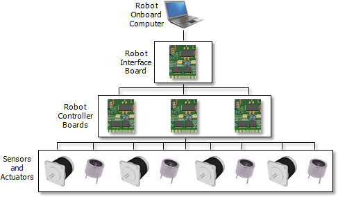 | Figure 6. Physical structure of robot-computer interfacing |
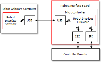 | Figure 7. Physical structure of robot-computer interfacing |
2.4. Medical Information Management
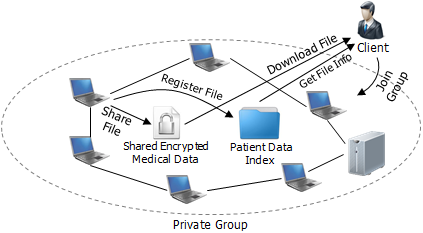
- Medical Information Management handles the storage, retrieval, presentation, creation, indexing, sharing and transmission of patient medical data using the P2P functionality supplied by the network engine. This component is shared by all the client entities in the network including robot, control station, local server and regular client, where in each entity, it has slightly different functionality.Medical data can be created or generated by three system entities – robot, control station and regular client. The medical data generated by Robot are radiograph images, blood pressure, pulse oximetry, and Vascular Doppler readings, and audio-video stream for real-time transmission to control station. These information are also transmitted to spectating clients and other participating clients at near real-time. To ensure timeliness of the medical data transmission from robot to control station, secured direct connection is used. As for control station, medical records, prescriptions and orders are written and updated by the physician digitally and transmitted to Robot via secured direct connection. These written documents are also stored distributedly in the private group (in peers). Figure 8 shows the robotic tele-diagnosis process.
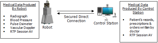 | Figure 8. Medical data creation and real-time transmission |
 | Figure 9. Overview of health information storage process |
 | Figure 10. Overview of medical data retrieval process |
2.5. Remote Robot Control Interface
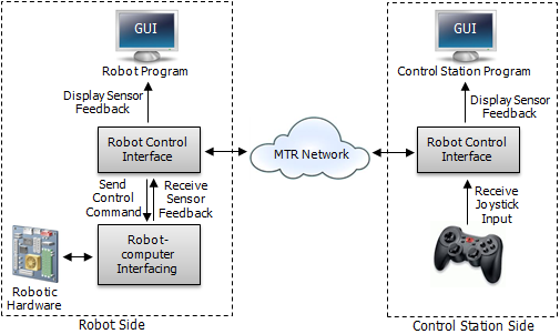
- Remote robot control interface (Figure 11) is designated for controlling Robot remotely thru Control Station. At Robot’s side, it links with robot interface software to obtain proximity sensors, inclinometers and digital compass readings that will be transmitted to Control Station. From the proximity sensors’ values obtained, Robot Control Interface then maps it to Robot Program GUI panel to display obstacles in Robots surrounding. Inclinometers readings will also be shown in Robot Program GUI to display ground inclination to prevent Robot from toppling while navigating the robot. Similarly, digital compass reading will be displayed to provide navigational guide. Robot Control Interface feeds the Robot-computer Interfacing component with control command received from Control Station thru MTR Network. At Control Station’s side, this component interfaces with a joystick to receive user input for controlling Robot. The joystick input is then interpreted and transmitted to Robot over MTR Network. Proximity sensors, inclinometers and digital compass readings received via MTR Network is displayed on Control Station Program GUI in similar layout to Robot’s side to give the operator information on Robot’s surrounding for easier, faster and safer Robot operation.
 | Figure 11. Overview of medical data retrieval process |
3. Experimental Results
- This section discusses the analysis, testing and experiment to gauge the design proposed by this research. Here, the critical components of MTR System will be tested for different criteria depending on their functions and purposes. The subsystems or components involved are, MTR Network, audiovisual system, Robot Control Interface and Medical Information Management. All these subsystems will be tested together at their normal operating conditions in a controlled environment to understand their behaviours, capacities and constraints.
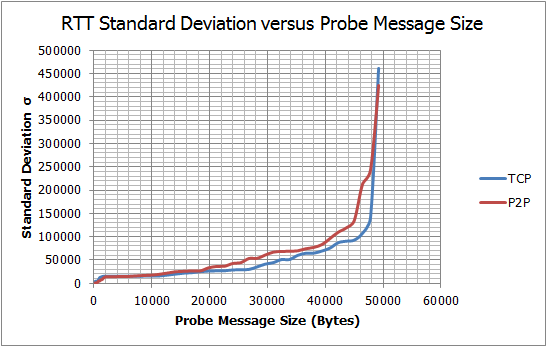
 | Figure 12. Round-trip test result |
 | Figure 13. Delay variation test result |
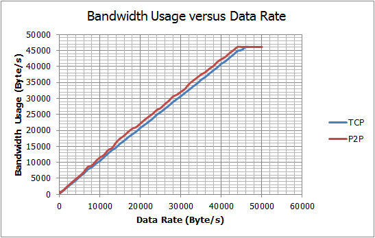 | Figure 14. Throughput test result |
3.1. Network Behavior
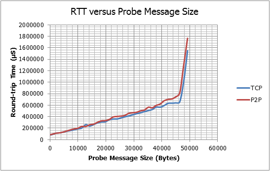
- This experiment is concentrating primarily on its proposed P2P engine to analyze its basic service metrics for throughput, jitter and delay. These characteristics are important in determining the reliability, quality and usability of the overall system especially in its robotic tele-diagnosis function. Figure 12, Figure 13 and Figure 14 are graphs derived from the experimental results. Referring to Figure 12 and Figure 14, the network is shown to possess similar RTT and data throughput characteristics to plain TCP for different data-rate and payload sizes but with small amount of delay and bandwidth overheads. These small fluctuating overheads observed in P2P tests may be caused by the PNRP control messages transmitted and received in the background to maintain the P2P graph. However, the larger component of these overheads are possibly caused by Grouping API’s security overhead. In Figure 13 both P2P and TCP tests have shown fluctuation in round-trip-time which can be equated as delay variation. By comparing the standard deviation graphs, P2P test has generally shown higher total delay variation than TCP. This effect possibly caused by Grouping security overhead.
3.2. AudiovisualPerformance
- This test aims to measure the end-to-end delay of the video streams received in Robot, Control Station and Regular Client.During the test, all the other components such as Medical Information Management and Robot-computer Interface are fully operational to simulate the complete MTR system. MTR’s RTD routine are simulated for 900 seconds each, generating 9000, 22500 and 18000 delay results for diagnosis video, navigation video and doctor video respectively. The test results are tabulated in Table 1. The tested video streams shown in Table 1 have delays lower than the recommended delay of 250ms for mission-critical telerobotic control mentioned in[30]. From the test results acquired for diagnosis and navigation videos, it is observed that the use of CUDA video decoders produces lower decoding delays than software decoders, which resulted in smaller end-to-end delays. The test results produced by doctor video have shown that CUDA encoders could reduce the encoding delays significantly, thus lowering the overall end-to-end delay of the video stream.
3.3. Remote Robot Control Performance
- This subsection tests the performance of the robot control function. The performance of the robot control function determines the safety, reliability and controllability of the Robot. During the test, the joystick at Control Station is randomly triggered to produce random control commands at random rates for 15 minutes. The computed respond delay values are then recorded to calculate its mean and delay variation. Table 2 shows the summarized results obtained from this test.The results obtained in this test have shown that MTR has an acceptable delay for a long distance robotic control. The delay is smaller than maximum tolerable delay for very critical missions including telesurgery that allows delays until 330 milliseconds for a safe operation[31].
|
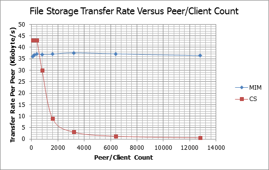 | Figure 15. File storage transfer rate |
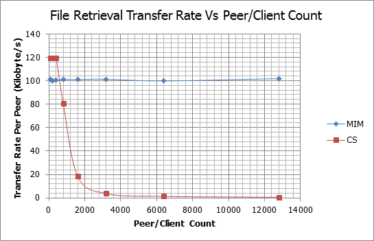 | Figure 16. File retrieval transfer rate |
3.4. MIM Data Storage and Retrieval Performance
- This section tests the feasibility and performance of the proposed distributed storage system in MIM on real-life scale, which involves large number of nodes. However, the cost for testing full-scale MTR’s P2P overlay is high because large number of peers (Regular Clients, Robots, Control Stations and Local Servers) is needed. Moreover, large P2P network is hard to test and coordinate in real-life because their test parameters and outcomes are spread across the network, thus hard to control and determine. Hence, in this research, software simulations are used to estimate the effectiveness of the MIM system proposed in this research instead of an actual test. This test uses open-source simulation software, OverSim to estimate the characteristics of MIM at different scale. The results of the simulations are presented in Figure 15 and Figure 16.From Figure 15 and Figure 16, it is observed that both storage and retrieval transfer rates of MIM are not affected by the increase of peer/client count, whereas, the transfer rates of the client-server setup have dropped exponentially when the client count increases over the server’s capacity. The MIM shows this characteristic because it exploits P2P’s self-scaling capability and limits the size of the P2P graph thru grouping. Large ungrouped P2P graphs have large communication overheads due to inefficiencies in broadcasting mechanisms like flooding.
4. Conclusions
- In this paper, a communication and control platform for Medical Tele-diagnosis Robotis presented. It consists of a peer-to-peer based network, audio-video communication module, robot-computer interfacing device, distributed medical information storage and retrieval system and remote robot control interface. The complete system was tested and simulated and was proven feasible.
References
| [1] | Noel Sharkey, "Death strikes from the sky: the calculus of proportionality," IEEE Technology and Society Magazine, vol. 28, no. 1, pp. 16 - 19, 2009. |
| [2] | Robert Sparrow, "Predators or plowshares? arms control of robotic weapons," IEEE Technology and Society Magazine, vol. 28, no. 1, pp. 25 - 29, 2009. |
| [3] | Se-gon Roh and Hyouk Ryeol Choi, "Differential-Drive In-Pipe Robot for Moving Inside Urban Gas Pipelines," IEEE Transactions on Robotics, vol. 21, no. 1, pp. 1 - 17, 2005. |
| [4] | Luis Basanez and Jan Rosell, "Robotic polishing systems," IEEE Robotics & Automation Magazine, vol. 12, no. 3, pp. 35 - 43, 2005. |
| [5] | Elena Garcia, Maria Antonia Jimenez, Pablo Gonzalez De Santos, and Manuel Armada, "The Evolution of Robotics Research," IEEE Robotics & Automation Magazine, vol. 14, no. 1, pp. 90 - 103, 2007. |
| [6] | Allison M. Okamura, Maja J. Mataric, and Henrik I. Christensen, "Medical and Health-Care Robotics," IEEE Robotics & Automation Magazine, vol. 17, no. 3, pp. 26 - 37, 2010. |
| [7] | Steven E. Butner and Moji Ghodoussi, "Transforming a Surgical Robot for Human Telesurgery," IEEE Transactions on Robotics and Automation, vol. 19, no. 5, pp. 818-824, 2003. |
| [8] | Garth H. Ballantyne and Fred Moll, "The da Vinci telerobotic surgical system: The virtual operative field and telepresence surgery," Surgical Clinics of North America, vol. 83, no. 6, pp. 1293–1304, 2003. |
| [9] | Kevin K. Chung, Kurt W. Grathwohl, Ron K. Poropatich, Steven E. Wolf, and John B. Holcomb, "Robotic Telepresence: Past, Present, and Future," Journal of Cardiothoracic and Vascular Anesthesia, vol. 21, no. 4, pp. 593-596, 2007. |
| [10] | Michelle J. Johnson, Xin Feng, Laura M. Johnson, and Jack M. Winters, "Potential of a suite of robot/computer-assisted motivating systems for personalized, home-based, stroke rehabilitation," Journal of NeuroEngineering and Rehabilitation, vol. 4, no. 6, 2007. |
| [11] | W.T. Brown et al., "Application of Robotic Stereotactic Radiotherapy to Peripheral Stage I Non-small Cell Lung Cancer with Curative Intent," Clinical Oncology, vol. 21, no. 8, pp. 623-631, 2009. |
| [12] | Lee E. Ponsky et al., "Initial evaluation of cyberknife technology for extracorporeal renal tissue ablation," Urology, vol. 61, no. 3, pp. 498-501, 2003. |
| [13] | Erhan Akdogan and Mehmet Arif Adli, "The design and control of a therapeutic exercise robot for lower limb rehabilitation: Physiotherabot," Mechatronics, vol. 21, no. 3, pp. 509-522, 2011. |
| [14] | Wen-Hwei Chen, Li-Jiuan Shen, Ru-Jiun Guan, and Fe-Lin Lin Wu, "Assessment of an automatic robotic arm for dispensing of chemotherapy in a 2500-bed medical center," Journal of the Formosan Medical Association, vol. 1, no. 1, pp. 1-8, 2012. |
| [15] | F. Corcione et al., "Advantages and limits of robot-assisted laparoscopic surgery: Preliminary experience," Surgical Endoscopy, vol. 19, no. 1, pp. 117-119, 2004. |
| [16] | Kartik Logishetty, Asheesh Bedi, and Anil S. Ranawat, "The Role of Navigation and Robotic Surgery in Hip Arthroscopy," Operative Techniques in Orthopaedics, vol. 20, no. 4, pp. 255–263, 2010. |
| [17] | Janusz Szymas, Guenther Wolf, Wielislaw Papierz, Bozena Jarosz, and Ronald S. Weinstein, "Online Internet-Based Robotic Telepathology in the Diagnosis of Neuro-oncology Cases: A Teleneuropathology Feasibility Study," Human Pathology, vol. 32, no. 12, pp. 1304-1308, 2001. |
| [18] | Jacob Rosen and Blake Hannaford, "Doc at a Distance," IEEE Spectrum, vol. 43, no. 10, pp. 34 - 39, 2006. |
| [19] | Beth Greenaway, "Impatient for robots," Engineering & Technology, vol. 3, no. 17, pp. 40 - 43, 2008. |
| [20] | Muhammad Iftikhar and Khalid Maood, "Telemedicine and Virtual Specialist Hospitals," in Computation World: Future Computing, Service Computation, Cognitive, Adaptive, Content, Patterns, 2009, p. 538. |
| [21] | Panos Trahanias et al., "TOURBOT and WebFAIR: Web-operated mobile robots for tele-presence in populated exhibitions," IEEE Robotics & Automation Magazine, vol. 12, no. 2, pp. 77 - 89, 2005. |
| [22] | Jader Wallauer, Douglas Macedo, Rafael Andrade, and Aldo von Wangenheim, "Building a National Telemedicine Network," IT Professional, vol. 10, no. 2, pp. 12 - 17, 2008. |
| [23] | Muhammad Ifthikar and Muralindran Mariappan, "Otorob (Ortho Robot) with Docmata (Doctor's Eye): Role of Remote Presence in Developing Countries," in Second International Conference on Advances in Human-Oriented and Personalized Mechanisms, Technologies, and Services, Porto, 2009, pp. 51-56. |
| [24] | M. G. Hadjinicolaou et al., "Emergency TeleOrthPaedics m-health system for wireless communication links," IET Communications, vol. 3, no. 8, pp. 1284 - 1296, 2009. |
| [25] | Christos Ilioudis, Athanasios Fevgas, Kyriaki Theodorou, Konstantinos Malizos, and Zoe Dailiana, "An innovative e-health network for collaboration on emergency cases," in 10th IEEE International Conference on Information Technology and Applications in Biomedicine, Corfu, 2010, pp. 1 - 4. |
| [26] | John F. Buford, Heather Yu, and Keong Lua Eng, P2P: Networking and Applications, 1st ed. Burlington: Morgan Kaufmann Publishers, Elsevier, 2009. |
| [27] | Beichuan Zhang, Wenjie Wang, Sugih Jamin, Daniel Massey, and Lixia Zhang, "Universal IP Multicast Delivery," Computer Networks, vol. 50, no. 6, pp. 781 - 806, 2006. |
| [28] | Christian Huitema, Clyde Hill, and John L. Miller,. US: Patent No. US7,065,587B2, 2006. |
| [29] | Ted H. Szymanski and Dave Gilbert, "Provisioning Mission-Critical Telerobotic Control Systems over Internet Backbone Networks with Essentially-Perfect QoS," IEEE Journal on Selected Areas in Communications, vol. 28, no. 5, pp. 630 - 643, 2010. |
| [30] | M. D. Fabrizio et al., "Effect of time delay on surgical performance during telesurgical manipulation," Journal of Endourology, vol. 14, no. 2, pp. 145 - 160, 2000. |
| [31] | Wen Tao Zhu, "A Cost-Efficient Secure Multimedia Proxy System," IEEE Transactions on Multimedia, vol. 10, no. 6, pp. 1214 - 1220, 2008. |