-
Paper Information
- Next Paper
- Previous Paper
- Paper Submission
-
Journal Information
- About This Journal
- Editorial Board
- Current Issue
- Archive
- Author Guidelines
- Contact Us
International Journal of Networks and Communications
p-ISSN: 2168-4936 e-ISSN: 2168-4944
2012; 2(5): 123-131
doi: 10.5923/j.ijnc.20120205.05
A New Backup Topology Design Method for Congestion Avoidance in IP Fast Reroute
 Abstract
 Reference
 Full-Text PDF
 Full-Text HTML
Simon Tembo 1, Ken-ichi Yukimatsu 1, Ryota Takahashi 1, Shoei Kamamura 2, Takashi Miyamura 2, Kohei Shiomoto 3
1Department of Computer Science and Engineering, Akita University, Akita City, Akita, 010-8502, Japan
2NTT Network Service Systems Laboratories, NTT Corporation, Tokyo, 180-8585, Japan
3NTT Network Service Integration Laboratories, NTT Corporation, Tokyo, 180-8585, Japan
Correspondence to: Simon Tembo , Department of Computer Science and Engineering, Akita University, Akita City, Akita, 010-8502, Japan.
| Email: |  |
Copyright © 2012 Scientific & Academic Publishing. All Rights Reserved.
We present a backup topology design method to avoid congestion in IP Fast Reroute. IP Fast Reroute techniques prepare backup topologies used to determine backup routes after a network failure. However, using more backup topologies consumes a lot of network resources. Reducing the number of backup topologies is a problem, as some links becomes overloaded. In this paper, we present a backup topology design method that splits the traffic on high load links to other links by considering network conditions, such as the traffic matrix or topology. The main idea of our method is the introduction of a concept called a Special Node, which is a node with a higher node degree, in the backup topology. We quantitatively illustrate the effectiveness of our method in terms of maximum link load reduction. The results show that, with the same number of backup topologies as the conventional method, our method can reduce congestion by 75%. It is effective for various topology models and not dependent to the network size. In this paper, we demonstrate that by selecting about 20% of the nodes as Special Nodes is very effective, particularly in large networks selecting Special Nodes whilst considering node position gives maximum effect. In this paper, we present that using our approach of selecting Special Nodes in the backup topology and then maximize the number of available links to the Special Nodes we can avoid congestion in IP Fast Reroute.
Keywords: IP Fast Reroute, Congestion Avoidance, Special Node, Backup Topology
Article Outline
1. Introduction
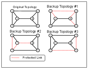
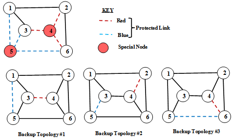
- IP Fast Reroute is a new approach to improve network reliability and availability. It reroutes data traffic to backup routes without waiting for the completion of the routing convergence after a network failure[1-4]. However, the rerouted traffic is likely to cause congestion on the backup routes if it is not carefully split among the alternative routes according to their available capacity[1]. MRC method proposed in[2], computes multiple backup topologies for all possible network failures. It pre-computes the backup routes using the backup topologies such that when nodes or links fail, the network delivers the packets as long as alternative routes exist. When a packet encounters a failure (see Figure 1), a failure ID is attached to the packet header (e.g. type of service (ToS) field) and the packet is sent to the backup next hop designated by the forwarding table associated with the failure ID[3-5]. The basic idea of IP Fast Reroute is to reduce recovery time after failure by using pre-computed backup topologies.On the other hand, using too many backup topologies consumes more network resources. It is necessary to recover more traffic with only fewer backup topologies for scalability reasons. This is because the number of backup topologies is proportional to the size of the forwarding table kept on a router, and link-state messages which are transmitted across the network. In addition, the size of ToS is limited. It is therefore important that we minimize the number of backup topologies. Minimizing the number of backup topologies will result in achieving a reduction in the number of forwarding tables[3-4]. To recover more traffic with fewer backup topologies for scalability is a good idea. However, some links will become overloaded if the number of backup topologies is reduced. The available number of links for backup routes in a backup topology is less than that in the original topology because several links are protected in a single backup topology. These protected links cannot be used to forward traffic (Figures 1 & 2). Thus, each backup route tends to use the few available links, causing them to become overloaded.
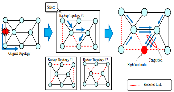 | Figure 1. Example of 3 Backup Topologies of the Original Topology |
 | Figure 2. Overview of the Backup Topology |
2. Multiple Routing Configurations
- In this section, we describe the characteristics of backup configurations used in the MRC method[3]. We introduce IP Fast Rerouting using backup topologies and then state our problem.
2.1. Characteristics of Backup Configurations
- IP Fast Reroute can be achieved by using backup topologies discussed in[2]. Each backup topology is pre-computed and installed in all routers. Backup topologies are used to define different topologies which have different link metrics for each of them. Each router computes the shortest route and then creates the routing entries based on the original topology, and for each backup topology. If the router detects a link failure, it searches for the backup topology that isolates the link corresponding to the failed link. Next, the identifier of the selected backup topology is marked in the ToS field of the IP header. After marking, the failure-detecting router forwards the packets to the next hop node according to the routing entry of the selected backup topology. Other routers can forward the IP packets according to the same backup topology by referring to the ToS field.In a backup topology, some links are defined as protected links (see Figure 2). They are not used to forward traffic when they fail. That is, backup routes are composed of links excluding the protected links. For purposes of recovery from an arbitrary single link failure, backup topologies should satisfy the following characteristics:1) Each link becomes a protected link on any backup topology.2) The backup topology is a connected graph that does not contain protected links.If backup topologies satisfy the above conditions, an arbitrary link is a protected link in at least one backup topology. Thus, for each link failure there is a backup topology that avoids the failed resources.
2.2. Overview of Fast Reroute Using Backup Topology
- Failure recovery in IP networks is critical for the network robustness and provisioning of high quality service. The main challenge is how to achieve fast recovery without introducing high complexity and resource usage. The main approaches used in current networks are route recalculation and lower layer protection. The disadvantages are: 1) Route recalculation could take as long as seconds to complete; while 2) Even if we use the IP fast rerouting technologies, redundant bandwidth is also required. IP Fast Reroute keeps additional routing information in the routers, thus allowing packet forwarding to continue on alternative links immediately after the detection of a failure[1-5],[10-11],[14-21]. IP Fast Reroute routers therefore have multiple forwarding information bases (FIBs) based on the original topology and backup topologies. If a packet arrives at a router, it searches for an FIB that matches a key composed of the failure ID and the destination IP address, and also for the next hop node that is described in the FIB. For example, in Figure 2, if node 1 detects the link 1-2 failure when the packets whose destination addresses are node 2 arrive at node 1, node 1 selects backup configuration #1 because the failed link (1-2) is protected. Then, these packets are forwarded to nodes 5, 6, and 2 according to backup topology #1 by referral to the ToS field. The failure ID is only written to the packets that seek to pass through a failure link. That is, traffic that does not use the failed resource is forwarded in accordance with the original topology[5].
2.3. Problem Statement
- We define our backup topology design approach as a balance link load after failure occurrence for IP fast reroute. In a backup topology, several links are protected, so the available number of links for backup routes is very few. This causes the recovered traffic to share the limited available links, and causing these links to become overloaded. The overloaded links become a contributing factor of congestion, causing degradation in the quality of services. In Figure 3 (a) we demonstrate that when we use the existing approach[2] for IP fast failure recovery, link 5-7 becomes overloaded. The problem is that due to lack of diverse routes, traffic flowing from source nodes 1, 3, and 6 to node 7 shares the same and only available link 5-7 because links 4-7, 6-7, and 7-8 are protected. Thus, link 5-7 becomes overloaded and a contributing factor of congestion[6]. We propose to solve the above problem by not increasing the number of backup topologies but to optimize the placement of protected links. If we increase the number of backup topologies, the ratio of protected links in a backup topology decreases. That is, increase of the number of backup topologies causes the increase of available links. However, increase of backup topologies also causes problems because the bit-size of ToS fields is limited and the number of forwarding tables is proportional to it. Therefore, we adopt our proposed approach of optimizing the placement of protected links, under the assumption that the available number of backup topologies remains the same as that of the conventional approach[2].
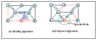 | Figure 3. (a) Existing approach. (b) Proposed approach |
3. Algorithm for Congestion Avoidance
3.1. Overview
- The key idea of our algorithm is the use of the Special Node in the backup topology based on the network conditions, such as the traffic matrix or topology. Based on these network conditions deciding criterion, we have two methods of defining the Special Node. These are the Load Order method and Degree Order method. 1) Load Order method: In this method, the Special Node is defined based on the traffic matrix. We first calculate the sum of incoming and outgoing traffic of each node. Then, the node with a high sum value is selected as a Special Node. The Load Order method requires traffic matrix information.2) Degree Order method: In this method, the Special Node is defined based on network topology. We first calculate the sum of the node degree of each node. The node degree is the number of links from a node. Then, the node with a high node degree is selected as a Special Node.Our algorithm starts by selecting the Special Node and then maximizes the number of available links from the Special Node. The link protection processes are divided into two steps: protecting the links around the Special Node, and then protecting links of other nodes. We then check whether the backup topology meets our characteristics. In Figure 5 the links around the Special Node are placed on different backup topologies by priority. Therefore, our algorithm can distribute the link load as much as possible. We have two methods for selecting the Special Node. The first method is to select the top K nodes that have a high link load (Top K method). The second method is to select the top K nodes in the same way but also considering the node position (Swapping K method). In both methods, Special Nodes are sequentially chosen. But, we do not need to select adjacent nodes as Special Nodes.
3.2. Algorithm
- We present the outline of our algorithm in Figure 4. The traffic matrix and topology are assumed to be the input data (traffic matrix is optional). The input parameter is the number of Special Nodes K, and the number of backup topologies N is the output. First, the initial N is defined as one. Then, the algorithm executes from STEP_1 through to STEP_4 continuously. In STEP_1 (a): The criterion for nodes to be defined as Special Nodes is decided. The criterion is determined by one of two methods as:1) Load Order whereby the Special Node is defined based on the traffic matrix. 2) Degree Order whereby the Special Node is defined based on network topologyIn STEP_1 (b): K Special Nodes are selected. The selection methods are as follows. 1) Top K method: the Special Nodes selected have a high link load.2) Swapping K method: these Special Nodes have a high link load and we also we consider their node position. If Special Nodes are adjacent, the effect of maximizing the number of available links is assumed to be reduced. Therefore, if the next Special Node is adjacent to a Special Node that has already been selected, we do not select such a node but instead sequentially select the next node as the Special Node candidate.
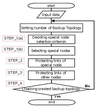 | Figure 4. Flow chart of our Algorithm |
 | Figure 5. Example of STEP_2 showing Links connected to Special Nodes grouped by color |
4. Performance Evaluation
- In this section, we discuss the effectiveness of our proposal quantitatively. We measured the link load after a possible single link failure.
4.1. Simulation Conditions
- We evaluated our algorithm in comparison to the existing algorithm[2]. The conventional method corresponds to the case of the number of Special Nodes K = 0. We evaluated our two methods (Load Order and the Degree Order) to define which nodes are Special Nodes. There are two methods of selecting the Special Nodes: the Top K method, and Swapping K method (which considers the node position). The evaluation index is the maximum link load at all the single link failures when K changes. The link load is normalized as one when the OSPF rerouting[6] is performed.
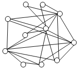 | Figure 6. Topology Model for HLDA (11 Nodes, 25 Links) |
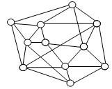 | Figure 7. Topology Model for COST239 (11 Nodes, 25 Links) |
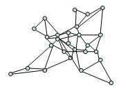 | Figure 8. Topology Model for COST266 (26 Nodes, 49 Links) |
4.2. Results and Discussion
4.2.1. Evaluation Results Considering Traffic Volume
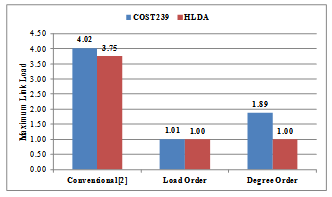
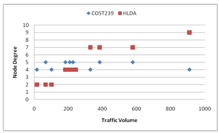
- The evaluation results shown in Figures 9-10 illustrate the effect of traffic volume on load reduction performance of our congestion avoidance algorithm when applied to HLDA and COST239 topologies. In Figures 9-10, we see that using the conventional method[2] (i.e. backup topology, N=3, Special Nodes, K=0) we experience problem of traffic concentrating on some links. Whilst, we experience minimum load levels when we use Load Order and Degree Order methods (i.e. with backup topology, N=3, Special Nodes, K=3) for IP fast failure recovery. Using Load Order method, we achieved a load reduction performance of 75% for COST239 and of 73% for HLDA. When using Degree Order method, we achieve a load reduction performance of 53% for COST239 and of 73% for HLDA.
 | Figure 9. Load Reduction Performance for COST239 and HLDA |
 | Figure 10. Correlation between each Node Degree and Traffic for COST239 and HLDA network models |
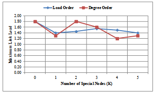
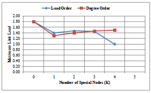
4.2.2. Evaluation Results Considering Node Position
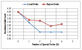
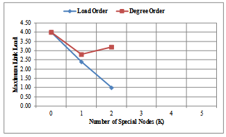
- The evaluation result given in Figures 11-14 illustrates the effectiveness of our proposed methods, the Load Order and Degree Order, in comparison with the conventional method[2] (with value for Special Node , K = 0), when we consider the node position of the high-load nodes. Figures 11-12 show the results of the maximum link load for COST239 model for each method. Figures 13-14 shows the results of the maximum link load for COST266 model for each method. The output is the number of backup topologies (N) which is 3 for COST239 model and 4 for COST266 model. In each evaluation result, we take note of the minimum value of the maximum link load as it is an important parameter for evaluation in each graph. Using the Load Order method (see Figures 11-12), the maximum load reduction effect for COST239 model is about 75% when compared to the conventional method[2]. The minimum value of the maximum link load for each method is, for conventional method = 4.0; Degree Order method = 1.8 (Top K method) and 2.8 (Swapping K method); and then for Load Order method = 1.0. Therefore, our approach of selecting Special Nodes in the backup topology and then maximize the number of available links to the Special Nodes is valid. Our algorithm has a high reduction effect on the maximum link load of each network model. The Load Order method has a higher load reduction effect than the Degree Order method when using Top K (Figure 11) and Swapping K (Figure 12) methods respectively. This is because the Special Nodes with the Load Order method are always high load nodes, while the Special Nodes with the Degree Order method are not necessarily high load nodes. If a topology is designed considering the traffic matrix, node degree is positively correlated with the incoming and outgoing traffic, and the Degree Order method can achieve the same effect as the Load Order method. However, traffic conditions may change after network operation begins, and correlation between node degree and traffic volume may decrease.
 | Figure 11. Results of Top K method for COST239 model |
 | Figure 12. Results of Swapping K method for COST239 model |
 | Figure 13. Results of Top K method for COST266 model |
 | Figure 14. Results of Swapping K method for COST266 model |
5. Related Works
- When failures occur in communication networks, failure recovery techniques provide reach ability, scalability, simultaneous failures recovery, and congestion avoidance on detour routes. IP Fast Reroute techniques have been studied for fast failure recovery achieving traffic in just a few milliseconds[1-5],[10-11],[14-21]. For scalability, a backup topology design method for reducing the number of backup topologies is necessary for reducing the router memory load[3-4]. As for simultaneous failures recovery, a backup topology design algorithm and extension of the forwarding mechanism were proposed[10]. Kvalbein et al.[11] proposed a link load balancing method for avoiding congestion by the route optimization approach. Their key idea is to apply the route optimization method[12] to the backup topology design problem. IP routing is determined by a link metric, which represents the cost of the link. Therefore, route optimization equals link metric optimization in an IP network. The basic idea of link metric optimization[12] is to distribute traffic as much as possible by preparing multiple routes called equal cost multi paths (ECMPs)[13] between the source node and destination node. In[10], the authors first generated a backup topology using the method in[2] and then optimized the link metrics of links excluding protected links using link metric optimization[12]. However, the problem of the approach in[11] is that their backup topologies lack diverse routes. We have illustrated in Figure 3 (a) that because the backup topology lack diverse routes to node 7, congestion will occur. That is, if there are no diverse routes in the backup topology, congestion remains to be a problem in the existing approach[2]. In Figures 9, 11-14 we have further demonstrated by simulation to prove this fact. Therefore, though the route optimization approach used in[2] has applicability but its backup topologies lack diversity routes for reach ability purpose. It is thus not a fundamental solution for the congestion avoidance problem as its available links are restricted in a backup topology.
6. Conclusions
- In this paper we have presented a backup topology design method to avoid congestion for efficient IP fast restoration. We have demonstrated the effectiveness of our approach as compared to the conventional method[2] through extensive simulation study. The results show that, with the same number of backup topologies as the conventional method[2], our method can reduce congestion by 75%. Moreover, our approach is effective for various topology models and it is not dependent to the network size. Our backup topology design method of avoiding congestion is even feasible to achieve robustness on actual IP networks. The key point of our method is the concept of introducing Special Nodes to the backup topology design method. We discovered that selecting about 20% of all of the nodes as Special Nodes is very effective. In particular, in larger networks selecting Special Nodes whilst considering the node position has the maximum effect. In our evaluation results we have demonstrated the effect of traffic volume on load reduction performance of our congestion avoidance method when applied to HLDA and COST239 models. When, for instance, we use the conventional method[2] (with backup topology, N=3, Special Nodes, K=0) we experience congestion problems on some links. Whereas, we have minimum load levels when we use Load Order and Degree Order methods (with backup topology, N=3, Special Nodes, K=3). Using Load Order method, we achieve a load reduction performance of 75% for COST239 and of 73% for HLDA. When we use the Degree Order method, we achieve a load reduction performance of 53% for COST239 and of 73% for HLDA. These evaluation results show that, the Load Order method is effective in reducing high link load. We discovered that in COST239 model by selecting high-load node as Special Nodes, we can improve the load reduction effect. Further the evaluation results show the effectiveness of our methods (Load Order and Degree Order) in comparison with the conventional method[2] when we consider the node position of the high-load nodes. The results show that with the backup topologies N=3 for COST239 model using the Load Order method the maximum load reduction effect for COST239 model is about 75% when compared to the conventional method[2]. Using COST266 model, which is larger than the COST239 model, the Load Order method performs better than the Degree Order method only when the node position is taken into consideration. Therefore the performance of the Load Order is better than the Degree Order. We think the effectiveness of the Load Order in a larger network is affected by the form of the topology and pattern of the traffic matrix, and if we consider the node position, the Load Order method improves better than the Degree Order method. We can therefore draw a conclusion that for larger networks selecting the Special Nodes for Load Order method it is better to consider the node position. Therefore, our approach of selecting Special Nodes in the backup topology and then maximize the number of available links to the Special Nodes is valid. As future work, we are investigating the combination of our algorithm and the backup route optimization method to maximally utilize our backup topologies. We expect the route optimization to reduce the number of backup topologies and network traffic. We will also investigate a base topology design method whose character is suitable for our design policy.