-
Paper Information
- Next Paper
- Previous Paper
- Paper Submission
-
Journal Information
- About This Journal
- Editorial Board
- Current Issue
- Archive
- Author Guidelines
- Contact Us
International Journal of Networks and Communications
p-ISSN: 2168-4936 e-ISSN: 2168-4944
2011; 1(1): 6-13
doi: 10.5923/j.ijnc.20110101.02
Ultra High Transmission Capacity of Undersea Optical Fiber Cables for Upgrading UW-WDM Submarine Systems
 Abstract
 Reference
 Full-Text PDF
 Full-Text HTML
Ahmed Nabih Zaki Rashed
Electronics and Electrical Communication Engineering Department, Faculty of Electronic Engineering, Menoufia University, Menouf, 32951, Egypt
Correspondence to: Ahmed Nabih Zaki Rashed , Electronics and Electrical Communication Engineering Department, Faculty of Electronic Engineering, Menoufia University, Menouf, 32951, Egypt.
| Email: |  |
Copyright © 2012 Scientific & Academic Publishing. All Rights Reserved.
This paper has proposed ultimate optical transmission of ultra multi transmission channels huge submarine cables has been investigated under different depth conditions. Conventional forward Raman amplification technique is considered taking into account the reduction of the four wave mixing (FWM). The double impact of both ambient temperature and pressure effects are also investigated. The transmission technique is studied namely Soliton propagation technique. As well as two multiplexing methods are considered in the design namely ultra wide wavelength division multiplexing (UW-WDM) and ultra-wide space division multiplexing (UW-SDM). Based on experimental data, both the deep ocean water temperature and pressure are tailored as functions of the water depth. The product of the transmitted bit rate and the repeater spacing is processed over wide ranges of the affecting parameters.Keywords Four Wave Mixing, Submarine Systems, Multiplexing Techniques, Soliton Propagation and Undersea Depths
Keywords:
Cite this paper: Ahmed Nabih Zaki Rashed , "Ultra High Transmission Capacity of Undersea Optical Fiber Cables for Upgrading UW-WDM Submarine Systems", International Journal of Networks and Communications, Vol. 1 No. 1, 2011, pp. 6-13. doi: 10.5923/j.ijnc.20110101.02.
Article Outline
1. Introduction
- To realize a long-haul high bit rate 1.5 μm undersea lightwave transmission system, the solution is to develop both a single longitudinal mode laser diode (LD) and dispersion shifted fiber to negate the effect of large chromatic dispersion in conventional fiber at 1.5 μm[1]. In developing submarine optical fiber cable for 1.5 μm operation, the ncreased sensitivity to bending loss during cabling and laying operations must be carefully considered. In addition a high accuracy measurement technique of optical loss and chromatic dispersion for the purpose of investigating long-length and high-bit-rate transmission potential must be established[2]. Compared with the conventional coaxial undersea cable systems, an optical fiber undersea cable system has a great technical and economical advantage. It is also suitable for digital transmission. Coaxial undersea cable systems have been used as one of the major transmission systems in international telecommunication networks over the past 25 years, and its channel capacity has rapidly been increased about ten times per decade with the growth in overseas traffic. However, this system has nearly reached a limit in its ability to increase the capacities of long-haul transoceanic systems from the standpoint of reliability and economy, although additional growth may be permitted with short-haul cable systems. On the other hand, the research and development on optical fiber communication systems progressed remarkably in the 1970’s, and a number of systems using 0.85µm wavelength have already been put into commercial services. Recently, the experimental systems using long wavelength and single-mode fibers are now actively being developed worldwide[3].The first undersea lightwave cable system installed in the Pacific Ocean was the third trans-pacific cable (TPC-3) system. The characteristic features of the TPC-3 system were 1.3μm signal wavelength, about 50 km repeater spacing, and the transmission bit rate of 280 Mbit/sec. The second system was the fourth trans-pacific cable (TPC-4) system and the technical features of this system were 1.55 μm signal wavelength, about 120 km repeater spacing, and the transmission bit rate of 560 Mbit/sec. Both systems were using 3R optical repeaters for the optical signal transmission. This type of the optical repeater had three functions as retiming, reshaping, and regenerating of the optical signal, and these functions were realized by the monolithically integrated electrical circuit At present there are several plans to install the lightwave cable system employing optical amplifiers[4]. Until the middle of 1990's, the fifth trans-Pacific cable network (TPC-5 CN) system was installed in the Pacific Ocean, and the twelfth and the thirteenth trans-Atlantic cable (TAT-12, 13) was installed in the Atlantic Ocean. These systems have the line bit rate of 5 Gbit/sec that is about eight times as much as that of the latest undersea systems using 3R repeaters[5]. The design of submarine cables is shaped by the submarine environment, which is very different than the environment for terrestrial cables. The underwater environment is very stable, very extreme, and very hard to reach. Repairs of undersea cables are difficult and expensive, so systems are designed to operate without service for long periods. Specifications usually call for no more than two underwater repairs in a cable's nominal 25 year life time, and the target is no repairs. Electrical power must be transmitted from the cable termination points on land, so power is at a premium. Early systems used repeaters, but since the mid-1990s all submarine cables have used only optical amplifiers underwater[6]. Full "three-R" regeneration, reshaping and retiming pulses as well as reamplifying them is done only at the cable termination points on shore. For intercontinental cable systems spanning thousands of kilometers, this imposes very stringent requirements on the levels of noise, dispersion, and nonlinear effects in the transmitting fiber and the optical amplifiers. The fiber-optic cables used in submarine systems are highly specialized, with fibers embedded deep in the core of a pressure-resistant structure. The outer layers of deep-sea cables are medium-density polyethylene. Heavy metallic armor covers the polyethylene in shallow-water cables, which are buried to protect them from fishing trawlers and ships' anchors-the undersea counterparts of backhoes. If undisturbed, the cable structure should withstand intense pressures and exclude salt water for decades[7]. Optical amplifiers are mounted inside pressure-resistant cases originally developed to house repeaters. They are built into the cable but are larger in diameter, so at first glance they resemble a rabbit swallowed by a python. Submarine cable developers still call these cases "repeaters," but don't be fooled-repeaters have not been used on submarine cables for several years (although the repeaters on old cables have not been replaced). Submarine cables fall into two broad classes, unrepeatered and repeatered in the world of submarine cables, these terms define whether or not the system includes optical amplifiers with their pump lasers in the same underwater housing as the optical amplifier. Underwater pump lasers mark a key dividing point because they are electronic components subject to failure, and because they require electrical power to be transmitted through the cable. These two types can be further subdivided according to the distance they span and their configuration, but we will concentrate on the basic categories[8].In the present study, we have investigated submarine cables to meet extremely tough requirements. Their transmission capacity should be as high as possible, because the cables are costly to make, lay, and operate. The cable, and any optical amplifiers or repeaters, must withstand harsh conditions on the bottom of the ocean for a design life of multi years. As well as we have modeled the integrated problem of optical undersea fiber cable, taking into account the effect of depth. The integrated problem is the product of the transmitted bit-rate and the repeater spacing where the following multiplexing technique is employed such as soliton propagation technique, two ultra multiplexing arrangements [ultra wide wavelength division multiplexing (UW-WDM) and ultra wide space division multiplexing (UW-SDM)], where ultra multi channels are transmitted through multi optical fiber links. Moreover forward Raman amplification method is employed, and the problem of four-wave mixing is reduced by increasing the channel spacing.
2. System Modeling Analysis
- Based on reported data of[9], the pressure-dependent Sellemeier coefficients and material dispersions for silica fiber glass will be cast under the form:
 | (1) |
 | (2) |
 | (3) |
 | (4) |
 | (5) |
 | (6) |
 | (7) |
 | . (8) |
2.1. Soliton Transmission Technique
- Soliton transmission is an alternative to the usual methods of transmitting a series of amplitude modulated digital pulses through a fiber-optic system. A laser source can generate a series of soliton pulses, Brs, Thus the presence of a pulse can mean a "1" and the absence can indicate a "0". Note that solitons must be spaced a certain distance apart to keep them from interfering with each other and that their return to "0" at the end of the pulse makes this signal RZ coded. The repeater spacing "Rs" has no effect, as we get "Brs" a distance-free quantity[15] as:
 | (9) |
 is the total chromatic dispersion coefficient in psec./(km.nm), Brsi is the soliton bit rate of the of the i-th channel, Ae is the effective cross section area of the guided mode in μm2, and n2n is the nonlinear refractive index coefficient (the Kerr coefficient). For pure silica n2n =3.2×l0-20 m2/Watt, while for Germania doped silica n2 is n2n= 3.2×l0-20 (1.0+2.81294x-16.6123 x2+45.9808 x3) in m2/Watt. The effective cross section area of the guided mode Ae, is:
 | (10) |
 | (11) |
 | (12) |
2.2. Forward Raman Amplification
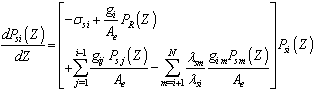
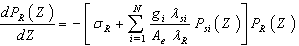
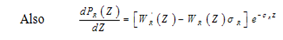
- For forward Raman amplification over a transmission distance Lf, the signal power Psi (i = 1, 2,....,N) and the Raman pump power PR are injected at Z = 0.0 and travel in the +Z direction. The differential equations governing the signals and pump propagation are given by[65].
 | (13) |
 | (14) |
 | (15) |
 | (16) |
 | (17) |
 There are two approaches for the calculation of g. The first one is due to[22]. The employed one is due to the work of[22] where:
 | (18) |
 | (19) |
 | (20) |
 | (21) |
 | (22) |
 minimum available detectable power which occur at amplified spontaneous emission (ASE)[24] as follows:
 | (23) |
 | (24) |
 | (25) |
 | (26) |
3. Simulation Results and Performance Evaluation
- We have investigated the transmission characteristics of undersea optical fiber cables to handle the product of the transmission bit rate and the repeater spacing for a cable of 36000 channel and multi optical links (40 to 360 link). Two real cases of advanced division multiplexing and advanced transmission method is processed namely soliton with forward Raman amplification technique is applied. The following items are applied in our performance analysis as follows:a) The total number of channel Nch.t (=36000 transmitted channels) is divided to subgroups equal to the number of links Nch.L where each link will transmit Nch L.= Nch.t/ NL.b) Channels of each subgroup are selected and grouped to be transmitted in each link. As the channels start from λ1 = 1.45 μm up to λ2 =1.65 μm, then the initial channel of subgroup is λi and the final one is λf where reduction of four wave mixing (FWM):
 | (27) |
 | (28) |
 | (29) |
 | (30) |
 | Figure 1. Variations of the spectral losses against undersea depth at the assumed set of parameters. |
 | Figure 2. Variations of the spectral losses against undersea depth at the assumed set of parameters. |
 | Figure 3. Variations of average repeater spacing against undersea depth at the assumed set of parameters. |
 | Figure 4. Variations of average repeater apacing against undersea depth at the assumed set of parameters. |
 | Figure 5. Variations of average soliton bit rate per channel versus number of links at the assumed set of parameters. |
 | Figure 6. Variations of average soliton bit rate per channel versus number of links at the assumed set of parameters. |
 | Figure 7. Variations of average soliton bit rate per link versus number of links at the assumed set of parameters. |
 | Figure 8. Variations of average soliton bit rate per link versus number of links at the assumed set of parameters. |
 | Figure 9. Variations of average soliton bit rate per fiber core versus number of links at the assumed set of parameters. |
 | Figure 10. Variations of average soliton bit rate per fiber core versus number of links at the assumed set of parameters. |
4. Conclusions
- The use of single mode fibers (with a core diameter of a few micrometers) was the more promising challenge to face. In addition, further progress in fiber manufacturing (mainly through better material purification) led to evidence of the second window around 1.3 μm, with an attenuation of about 0.4 dB/km. Moreover, the bulk silica chromatic dispersion vanishes close to 1.3 μm; it was therefore possible to propagate high transmission bit rate pulses with minimum pulse broadening. As well as the problem of Ultra Wideband Wavelength Division Multiplexing plus the problem of Ultra Wide Space Division Multiplexing in nonlinear submarine optical cables with conventional Raman amplification techniques are investigated through real transmission technique. The impact of tailoring of chirped pulses of different temporal waveforms is investigated in a normal dispersion fiber. The set of multiplexed signals are tailored in a different a subset to assure approximately the same output level of power to hold the signal to noise ratio at the same level. Moreover, soliton propagation is employed with cohere successive section of alternating dispersion are used also as a technique to manage the dispersion. Distributed "Raman" amplifiers is engaged to maximize the repeater spacing. It is theoretically found that the increased number of links in the fiber cable core and undersea depths, this result in increasing average repeater spacing and then to decrease the spectral losses within silica-doped and plastic based submarine fiber link. Moreover it is evident that the increased of both number of links and undersea depths, this leads to increase in transmission bit rates either per link or per channel and then to increase transmission bit rates per fiber cable core. It is indicated that the silica-doped based submarine fiber link has presented lower spectral losses and higher both repeater spacing and soliton transmission bit rates either per link or per channel than plastic links.