International Journal of Metallurgical Engineering

p-ISSN: 2167-700X    e-ISSN: 2167-7018

2017;  6(2): 31-35

doi:10.5923/j.ijmee.20170602.01


Feasibility Study of Dephosphorization of Slag Generated from Basic Oxygen Furnace of an Integrated Steel Plant

Vikash Kumar, Somnath Kumar, Jwala Prasad, K. K. Keshari, Somnath Ghosh, Asit K. Bhakat

Research & Development Centre for Iron & Steel, Steel Authority of India Limited, Ranchi, India

Correspondence to: Asit K. Bhakat, Research & Development Centre for Iron & Steel, Steel Authority of India Limited, Ranchi, India.

Email:

Copyright © 2017 Scientific & Academic Publishing. All Rights Reserved.

This work is licensed under the Creative Commons Attribution International License (CC BY).
http://creativecommons.org/licenses/by/4.0/

Abstract

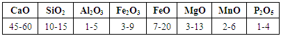
Basic oxygen furnace slag (BOF slag) is an unavoidable by-product of steelmaking process of basic oxygen furnace. The main chemical constituents of BOF slag are CaO, FeO, Al2O3, SiO2 and MgO. Due to its high metallic value (FeO: 16-20%) and lime content (CaO: 45-50%), it is possible to use in iron making and steelmaking process to replace lime and recover iron and CaO. But it also contains some P2O5 around 2 – 3% which is too high for recycling. The objective of this study is to investigate the removal of phosphorus by magnetic separation technique. The slag generally contains a Ca19Fe2(PO4)14 (phosphorus enriched phase) with FeO-CaO-SiO2 matrix phase. X-ray fluorescence (XRF), X-ray diffraction (XRD) and Scanning electron microscope (SEM) analysis were carried out for characterizing different property of BOF slag. The slag was then crushed and heated at several rates and dwell time up to 1500°C. Afterward it was cooled to 1400°C at the rate of 1°C/min with holding period of 240 min and then quenched with water. The cooled slag was then crushed, milled and separated by wet magnetic separation method. Since the magnetic properties differ for different phases, it is possible to separate each phase with the aid of magnetic separation. By applying magnetic field to the crushed slag sample, phosphorus lean and rich phases may be notably separated.

Keywords: Basic oxygen furnace slag, Dephosphorization, Wet magnetic separation, Characterization, Magnetic field

Cite this paper: Vikash Kumar, Somnath Kumar, Jwala Prasad, K. K. Keshari, Somnath Ghosh, Asit K. Bhakat, Feasibility Study of Dephosphorization of Slag Generated from Basic Oxygen Furnace of an Integrated Steel Plant, International Journal of Metallurgical Engineering, Vol. 6 No. 2, 2017, pp. 31-35. doi: 10.5923/j.ijmee.20170602.01.

1. Introduction

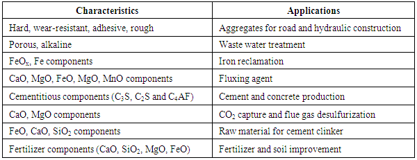
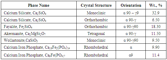
Large quantities of steel slag are generated by the various steelmaking processes; of which basic oxygen furnace slag accounts larger fraction [1]. Steel and steel slag annual output of 2013 in India reached to 81.20 million tons and 11.36 million tons respectively. However, the current utilization rate of steel slag in India is only 20 % i.e. 2.27 million tons, far behind the developed countries like USA, Australia and European Countries etc. of which the rates have been 70, 70 and 80% respectively [2]. However, with steel production on the rise, slag production is also expected to increase manifold. In contrast with other nations, most slag produced in India, especially steel slag is discarded. However, this is increasingly becoming a problem due to paucity of land. These BOF slags are for recycled into two main ways; external reuse for road construction and hydraulic engineering, fertiliser etc and Internal recycling within integrated steelworks as feed to the sinter plant or to BOF to utilise useful elements such as Fe, Mn, CaO, MgO [3-7]. Characteristics of compounds in slag and its application are shown in Table 1 [8]. Due to presence of high amount of Ca, it can be used as flux in blast furnace, but presence of high amount of phosphorus in the LD slag makes unsuitable for industrial application as it is a detrimental element for high quality steel products which limits the use of BOF slag in sinter making and Blast Furnace. As steel quality requirements have increased so the need for lower phosphorous levels has led to a reduction in the quantity of steel slag that is recycled.
Table 1. Characteristics of components and their applications
     
Farshid Pahlevani studied the distribution ratio of P2O5 between the solid solution and the liquid slag phase was measured for various slag compositions [9]. A typical chemical analysis of slag is shown in Table 2 [8].
Table 2. Chemical analysis of a typical BOF slag,Wt%
     
When slag is recycled the phosphorous content build up as the process progress. Detrimental effects of phosphorus in steel include various forms of embrittlement which reduce the toughness and ductility. The most familiar example in this category is the classic phenomenon of temper embrit-tlement in heat-treated low-alloy steels resulting from seg-regation of phosphorus and other impurities at prior austen-ite grain boundaries. So the need of dephosphorization ap-pears. Dominating elements in BOF slag are Ca, Fe and Si, with smaller quantities of Mn, Mg, Al, P and few others. The mineral composition is also very variable; it is a func-tion of chemical composition, cooling rate, etc. The com-mon mineral phases present in BOF slag include merwinite (3CaO.MgO.2SiO2), olivine (2MgO.2FeO.SiO2), C2S(2CaO.SiO2), C4AF(4CaO.Al2O3.Fe2O3), C2F(2CaO.Fe2O3), free lime (CaO), C3S (3CaO.SiO2), MgO, FeO, and the RO phase (a solid solution of CaO-FeO-MnO-MgO). Phosphorous in particular is distributed in a number of phases, such as dicalcium silicate (C2S), tricalcium silicate (C3S) and the matrix.
In general, slag can be divided into three major phases in its solidified micro-structure: FeO-free phosphorus-rich phase (Ca3P2O5-Ca2SiO4), a phosphorus-free manganese-enriched phase (mangano-wustite phase), and a phosphorus-free matrix phase (FeO-CaO-SiO2) containing minor part of manganese. The main components of slag are CaO, FeO, SiO2 and P2O5.
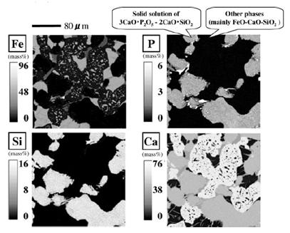
Figure 1. EPMA mapping image of a BOF slag
Figure 1 shows the structure and phosphorus distribution among the phases precipitated in a slag, as observed by energy-dispersion type electron-probe microanalysis (EPMA) [10]. The white parts in upper right-hand picture have high concentrations of phosphorus but no FeO. The black parts in this picture consist mainly of FeO–CaO–SiO2, an almost phosphorus-free phase. It is known that phosphorus in slag generally shows remarkable segregation as solid solutions of calcium phosphate and di-calcium silicate, which depends on the total slag composition [11]. X. R. Wu et. al observed that C2S phase is the major crystalline phase, which may concentrates almost all phosphorous and was termed as the phosphorous concentrating phase. The maximum phosphorous content of the C2S phase may rise upto 6.39wt-% P2O5 [12]. Because these two phases have totally different magnetic properties, they can be separated by applying a strong magnetic field. Many researchers [13-15] have tried to remove phosphorous from different source of phosphorous by various method. The sources may be Iron ore, Slag, Sludge and different phosphorus containing alloys etc. Reduction method, Leaching, Flotation method, vacuum refining and Microwave radiation methods are some of the processes which are in use widely. Hitoshi Ono et al [16] studied the removal of phosphorus from LD slag by floating separation of Dicalcium Silicate during solidification. On slow cooling from high temperature the slag is separated in two layers, CaO, SiO2 and P2O5 are segregated in the top layer and FeO, Fe2O3 and MnO in the bottom layer.
The efficiency of separation depends on following factors:
1. Difference in density between dicalcium silicate and re-maining liquid, the higher the difference easier the separa-tion.
2. Viscosity of liquid slag which becomes high with low FeO content blowing of oxygen helps in improving the separation of P2O5 from slag.
3. Size of crucible, the more is the depth better is the sepa-ration.
4. Slag composition which determines the viscosity, the lower is the basicity clearer the separation. Fluorspar helps in improving the fluidity.
5. Starting temperature of cooling, the higher it is better is the separation ratio of P2O5. The difference between liquidus and starting temperature of crystallization should be at least 1000°C for best results.
6. Cooling rate, the separation is better if the cooling rate is below 2°C. Floating speed of di-calcium silicate particles is affected by particle size. The growth of particle during its ascent in liquid bath increases as the cooling rate decreases.
7. Effect of blowing oxygen, suspended Fe and FeO get oxidized to higher oxides like FeO and Fe2O3. As the oxida-tion reaction is exothermic, the temperature of slag increases which helps separation of P-rich phase.

1.1. Magnetic Separation Methods

Magnetic separation is a process in which magnetically susceptible material is extracted from a mixture using a magnetic force. Slag contains various complex compounds. These compounds have different magnetic property. By taking advantages of these magnetic properties, magnetic and non-magnetic particles may be separated by using a magnetic separator. In this paper above method is used for effective removal of phosphorous containing phases.

2. Experimental

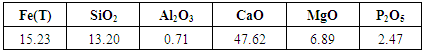
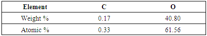
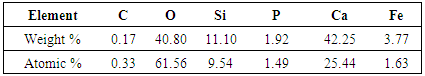
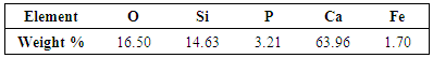
Basic Oxygen Furnace slag was collected from Steel Authority of India Ltd, Rourkela Steel Plant. This slag sample contains phosphorous oxide as high as 2.47%. The compositional analysis of this sample was done by X-ray fluorescence (XRF) and it is shown in Table 3.
Table 3. Chemical composition of BOF slag (RSP) done in XRF
     
Scanning Electron Microscope was done for investigating elemental distribution and point analysis of sample. XRD was also done for quantitative and qualitative analysis of the phases present (Table 4).
Table 4. Phases Present, its crystal structure and Wt%
     
250g of the slag sample was taken in alumina crucible for melting it in tubular furnace. Melting behaviour of slag was analysed using Hot stage microscope and Fact Sage. Hot stage microscope shows that as the temperature is increasing the specimen changes its shape. The change in shape is due to getting plastic or fluid property at higher temperature. This phenomenon is shown in Figure 2. Change in shape with respect to temperature and time varies for different composition of slag. The slag used in this experiment has got flowing property at 1408°C.
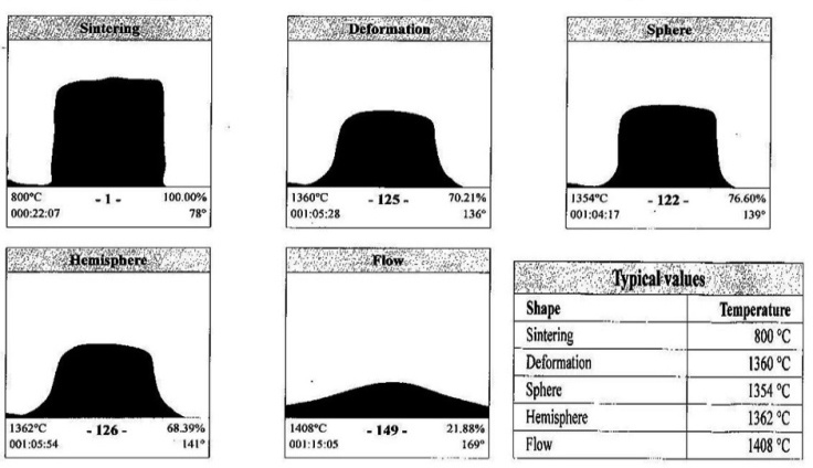
Figure 2. Shape of slag with variation in temperature
The temperature was first increased from room temperature to 1000°C at the rate of 6°C/min and then it was kept at this temperature for 15 min. Further temperature was increased to 1200°C, 1300°C, 1400°C, 1500°C at the rate of 7°C/min, 5°C/min, 4°C/min, and 3°C/min with dwell time 15 min, 15 min, 15 min, 10min respectively. After holding for about 10min at the temperature of 1500°C, the slag was cooled to 1400°C at a cooling rate of 1°C /min, and then held for 240 min at this temperature before quenching in water. Distribution of phases was verified by using Scanning Electron Microscope (SEM). Sample was then crushed to very fine size and 50 gms of the melted slag sample was taken in a beaker containing 800ml water. It was stirred continuously to make the slurry homogenous. When the slurry became homogeneous it was fed into the wet magnetic separator. The magnetic separator was operated at 14A current, 60V DC voltage and 10,500 Gauss (1.05T). The slurry was then poured in funnel shaped inlet. All magnetic materials adheres to the inside wall of the separator and all non-magnetic materials are collected in a container through the outlet. When the magnetic separator was turned off, all the magnetic materials which was adhered to the wall gets detached. By this process we got two slurries, one with magnetic particles and another with non-magnetic particles. These slurries are allowed to settle down for 24 hours and then dried in an oven for around one and half hours for complete removal of moisture. Then XRF analysis of these two products was done separately.

3. Results and Discussion

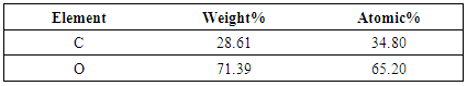
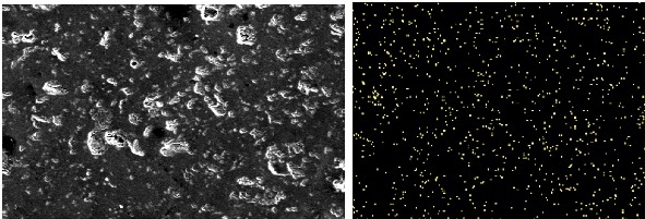
P2O5 content of slag is generally very high for recycling purpose. Hence this slag needs to be processed. This phos-phorous oxide present in slag was found in various complex phases, Phosphorus containg phase is Calcium Iron Phos-phate (Ca19Fe2(PO4)14 and Ca9Fe(PO4)7). This two forms of phase carries weights around 20% of total wt%. The distri-bution of phosphorous in elemental form was investigated using SEM analysis. SEM image in Figure 3 clearly shows that phosphorus distribution in matrix is random.
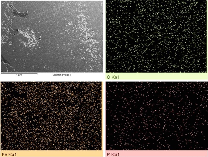
Figure 3. Distribution of Phosphorous, Iron and Oxygen in Slag
Distribution of elements and their respective amounts has been investigated at three different location of slag matrix. Figure 4 is showing the point analysis at location 1, 2 and 3 while Weight % of elements at these location is tabulated in Table 5 a), b) and c) respectively.
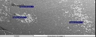
Figure 4. Points in slag where analysis was done
Table 5a. Wt and Atomic % of elements at Spectrum 1
     
Table 5b. Wt and Atomic % of elements at Spectrum 2
     
Table 5c. Wt and Atomic % of elements at Spectrum 3
     

3.1. Characterization of Treated BOF Slag

Elemental distribution in treated slag indicates the localized segregation of phosphorus in matrix (Figure 5).
Figure 5. Elemental distribution of Phosphorous in treated Slag
This was due to the fact that during melting and holding of slag at high temperature makes phase rearrange themselves to equilibrium. Point analysis of elements in matrix at four different locations was done to confirm the redistribution of phases. Spectrum 3 in Figure 6 is the locations where phosphorous presence was maximum as found in SEM analysis.
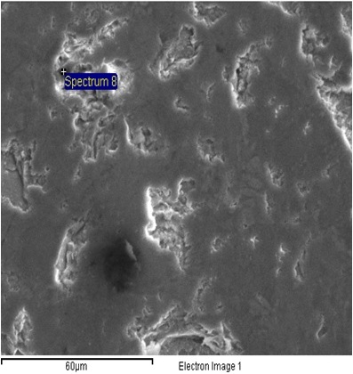
Figure 6. SEM Point analysis of BOF treated slag
Weight % of different elements with phosphorous has been tabulated in Table 6. When these SEM images were com-pared with images of SEM done before the treatment of slag it was concluded that after the treatment of slag sample phosphorous gets concentrated at some specific locations.
These locations are the phases which may be mainly Di-Calcium Silicate phase. And this particular phase has great absorption capacity of phosphorus. Moreover this phase is nonmagnetic in nature. So using the magnetic field, separation of phosphorous rich and lean phase can be done.
Table 6. Wt and Atomic % of elements at Spectrum 3
     

3.2. Magnetic Separation

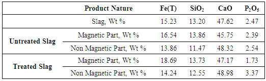
Magnetic separation was carried out for separating the treated slag using water as a carrier media. After magnetic separation two type of products were obtained viz. a) slag with major magnetic portion b) Slag with fewer magnetic portion. Same experiment was also done without any melting of slag and expected result was found as phosphorus level didn’t get much affected by only magnetic separation. Table 7 shows the phosphorous content in different type of treated slag. Chemical analysis of these products was done for observing phosphorus contents in products and result confirms that it is possible to get phosphorous rich and lean phases using this method.
Table 7. XRF analysis of Magnetic and Non magnetic product obtained after magnetic separation of slag
     
From the above results we can see that phosphorous rich phase was collected in non-magnetic sample. This is also the part with greater content of calcium oxide. The amount of phosphorous present in non-magnetic sample is 3.37 %.

4. Conclusions

Dephosphorization of Basic Oxygen Furnace slag is feasible if certain condition is maintained.
This process can benefit steel industries by reducing phosphorus load in input material.
Heating and cooling cycle enabled the segregation of phosphorus in different phases. This segregation is enhanced with slow cooling.
The phosphorous lean phase can be recycled in an iron and steel industry in various ways like feeding material for Blast furnace, sinter plant etc.
Techno-Economical feasibility of this process needs to be checked for industrial scale.
More research is required in this field in order to carry out dephosphorization more effectively.

ACKNOWLEDGEMENTS

Authors would like to express highest sense of appreciation for guidance of the members of the steel making group and management of RDCIS-SAIL, Ranchi, India. Their efforts support and influence in shaping this work to its completion is greatly valued.

References

[1]  Yildirim I Z and Prezzi M, “Chemical, Mineralogical, and Morphological Properties of Steel Slag”, Advances in Civil Engineering, Volume 2011, Article ID 463638, doi:10.1155/2011/463638, pp 1-13, 2011.
[2]  Tiwari M K, Bajpai S and Dewangan U K, “Steel Slag Uti-lization — Overview in Indian Perspective”, International Journal of Advanced Research, Volume 4, Issue 8, pp 2232-2346, 2016.
[3]  Das B., Prakash S., Reddy P.S.R. and Misra V.N., “An over-view of utilization of slag and sludge from steel industries”, Resources, Conservation and Recycling, Volume 50, Issue 1, pp 40-57, 2007.
[4]  Chaurand P, Rose J, Briois V, Olivi L, Hazemann J L, Proux O, Domas J, and Bottero J Y., “Environmental impacts of steel slag reused in road construction: A crystallographic and molecular (XANES) approach”, Journal of Hazardous Materials, 139 (3), ISSN 0304-3894, pp 537-542, 2007.
[5]  Topkaya Y., Sevinç N. and Günaydın A., “Slag treatment at Kardemir integrated iron and steel works”, International Journal of Mineral Processing, Volume 74, Issues 1–4, pp 31-39, 2004.
[6]  Radosavljevic S, Milic D and Gavrilovski M, “Mineral Processing of a Converter Slag and Its Use in Iron Ore Sin-tering”, Magnetic and Electrical Separation, Volume 7, Issue 4, pp 201-211.1996.
[7]  Nashiwa H, Mizuno T, Ohi J and Katohgi K, “Effective use of returned LD slag and dolomite and operation with sublance system”, Ironmaking Steelmaking, Volume 5, No 3, pp 95–102, 1978.
[8]  Huang Yi, Guoping Xu, Cheng Hu, Wang Ju, Wan Y and Chen H, “An Overview of Utilization of Steel Slag”, The Seventh International Conference on Waste Management and Technology (ICWMT 7), Volume 16, pp 791-802, 2012.
[9]  Pahlevani F, Kitamura S, Shibata H and Maruoka N, “Dis-tribution of P2O5 between Solid Solution of 2CaO•SiO2–3CaO•P2O5 and Liquid Phase”, ISIJ International, Volume. 50, No. 6, pp. 822–829, 2010.
[10]  Kazuyo M Y, Hironari K, Kenichi N, Tetsuya N, “A Material Flow Analysis of Phosphorus in Japan” Journal of Industrial Ecology, Volume 13, Issue 5 Pp 687–705, 2009.
[11]  Futatsuka, T., Shitogiden K., Miki T., Nagasaka T., and Hino M., “Dissolution behavior of nutrition elements from steel-making slag into seawater”, ISIJ International Volume 44, No 4, pp 753–761, 2004.
[12]  Wu X. R., Yang G. M., Li L. S., Lu H. H., Wu Z. J. and Shen X. M., “Wet magnetic separation of phosphorus containing phase from modified BOF slag”, Ironmaking & Steelmaking, Volume 41, Issue 5, pp 335-341, 2014.
[13]  Kazuki M, Muxing G, Norio O and Nobuo S, “Resurrection of the iron and phosphorus resource in steel-making slag” , Journal of Material Cycles and Waste Management, Volume 4, Issue 2, pp 93–101, 2002.
[14]  Jung S M, Do Y J and Choi J H, “Reduction Behaviour of BOF type Slags by Solid Carbon”, Steel research international, Volume 77, Issue 5, pp 305–311, 2006.
[15]  Wang S H, Wu Y Q, Liu X S, Xu Z R and Lu X F, “Experi-mental Study on Gasification Dephosphorization of Converter Slag With Reduction by Silicon”, Iron and Steel, Volume 43, Issue 2, pp 31-34, 2008.
[16]  Ono H, Inagaki A, Masui T, Narita H, Mitsuo T, Nosaka S, Gohda S, “Removal of Phosphorus from LD Converter Slag by Floating of Dicalcium Silicate during Solidification” , Tetsu-to-Hagane, Volume 66, No. 9, pp 1317-1326, 1980.