Oke Samuel Ranti1, Talabi Henry Kayode1, Olorunniwo Olusegun Emmanuel2, Atanda Pethuel Olayide2, Aramide Fatai Olufemi1
1Department of Metallurgical and Materials Engineering, Federal University of Technology, Akure, Nigeria
2Department of Materials Science and Engineering, Obafemi Awolowo University, Ile-Ife, Nigeria
Correspondence to: Aramide Fatai Olufemi, Department of Metallurgical and Materials Engineering, Federal University of Technology, Akure, Nigeria.
| Email: |  |
Copyright © 2015 Scientific & Academic Publishing. All Rights Reserved.
This work is licensed under the Creative Commons Attribution International License (CC BY).
http://creativecommons.org/licenses/by/4.0/

Abstract
The mechanical properties of clay bonded carbon refractory produced from Ifon clay and spent graphite electrode was investigated. This was carried out following American Society for Testing and Materials (ASTM) stipulated standards. The spent graphite electrode that was utilized was produced by grinding the graphite electrodes using a ball mil. The mixture of clay and spent graphite electrode was made using ball-mill for six hours using 40, 50, 60 and 70 weight percents of Ifon clay in each mix. Each mixture was uniaxially compressed into standard samples dimension and then fired in the furnace at varied temperatures of 700°C, 800°C, and 900°C. The investigated properties were bulk density, cold crushing strength, porosity, Young’s modulus and absorbed energy. The results show that for the 700°C sintered products there appears to be an increase in bulk density of the produced clay bonded refractory with increase in the clay content. The porosity of the sample decreases with the increase in clay content. The young modulus, absorbed energy and cold crushing strength of the refractory increased with increase in weight percentage of the clay content. It is observed that there is a reduction in the young modulus, absorbed energy and cold crushing strength as a result of increase in the sintering temperature. It was concluded that the sample sintered at 700°C possess superior mechanical properties.
Keywords:
Carbon refractory, Clay, Porosity, Spent graphite electrode, Sintering
Cite this paper: Oke Samuel Ranti, Talabi Henry Kayode, Olorunniwo Olusegun Emmanuel, Atanda Pethuel Olayide, Aramide Fatai Olufemi, Production and Characterization of Clay Bonded Carbon Refractory from Ifon Clay and Spent Graphite Electrode, International Journal of Metallurgical Engineering, Vol. 4 No. 2, 2015, pp. 33-39. doi: 10.5923/j.ijmee.20150402.02.
1. Introduction
Refractory materials are inorganic materials which can withstand high temperatures under the physical and chemical action of molten metal, slag and gases in the furnace [1-3]. Refractory products are majorly required in the metallurgical industries for various processes in furnace construction, smelting vessels for holding, transporting metal and slag, in furnace heating, and in the flues or stacks through hot gases are conducted [4-5]. The Nigerian Government has reiterated its commitment towards the development and resuscitation of moribund steel and rolling mills companies which is believed to liberate her economy and reduce the dependence on crude oil. It was reported that the Ajaokuta Steel Company and Delta Steel Company will, at full capacity, respectively require 43,503 and 25,000 tons per year of fireclay refractories for their activities [6-8]. Other rolling mills within the country also rely on refractories for its production. Other demands for these products come from chemical, hardware, cement and glass industries. The refractory needs of these industries were well over 300,000 tons as the year 2000 [9].Despite the huge amount of clay deposits available in Nigeria and the enormous research that have been carried out in the development of refractory products, refractory industries are yet to spring up in the country. Nigeria continues to depend on external sources of refractory materials for many of its industries [10-11].There has been a general drive towards the development of our local materials for the production of refractories to meet our industrial and technological requirements at the same time improving the mechanical properties [1-11]. This has given impetus to research works targeted towards the development of refractory products from local clay deposits with a view of determining their suitability for adoption as refractory materials for different metallurgical and process industries. Aramide and Oke [12] studied the production and characterization of clay bonded carbon refractory from carbonized palm kernel shell. They reported that the refractory produced was suitable for refractory application. Hassan and Aigbodion [13] in an earlier research on the Effect coal ash on some refractory properties of alumino-silicate (Kankara) clay for furnace lining. The work has found out that medium duty fireclay brick capable of possessing good thermal shock resistance was made with this blend at 25 wt% coal ash. Aramide [14] investigated the effects of sintering temperature on the phase developments and mechanical properties of Ifon clay; he reported that the sintering temperature was varied between 800°C and 1200°C. He then concluded that the sample that was sintered at 800°C possess the optimum property. Among all the systems studied by the mentioned researchers, it can be noticed that no experimental data have been provided for using spent graphite electrolyte to improve the refractory property of Ifon clay. The motivation for choosing to incorporate spent graphite electrode (recycle spent graphite electrode) into Ifon clay is to ascertain the viability of developing a refractory with improved mechanical properties beyond the level achievable with the use of only Ifon clay. This research focuses on the enhancement of mechanical properties of Ifon clay in Ose Local Government Area of Ondo State with the addition of spent graphite electrolyte.
2. Materials and Methods
2.1. Materials
The materials utilized in this research work are Ifon clay and spent graphite electrode. The Ifon clay was collected from Ifon (an area fond to be rich in fireclay), Ose Local Government Area of Ondo State (latitude 7° 52` N and longititude 7° 28` 60 E). The clay lumps were crushed, grounded and sieved.
2.2. Clay Processing Procedure
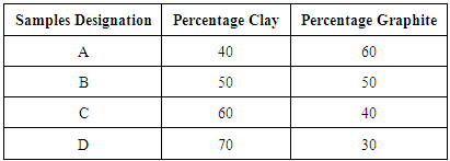
The clay sample as obtained was soaked in water for three days to dissolve the clay and at the same time to form slurry. The resulting slurries were then sieved to remove dirt and other foreign substances using a sieve. These were then allowed to settle down for seven days after which the floating clear liquids were decanted. The settled fine clays is then poured into Plaster of Paris (P.O.P) moulds and left undisturbed for three days in other to allow the liquid present to drain out completely. The resulting plastic clay mass were sun dried and subsequently dried in a laboratory oven at 110°C for 24 hours to remove moisture content completely. The resulting dried clay samples were milled at 300 rev/ min for 4 hour to an average particle size of about 150µm. The average particle size of the spent graphite electrode reduced to 1000µm by grinding in a ball mill. The mixture of clay and spent graphite electrode was made using ball-mill for six hours using 40, 50, 60 and 70 weight percents of Ifon clay in each mix. Each mixture was mixed thoroughly with a little addition of water to induce some plasticity. The samples were then compressed uniaxially inside a standard stainless steel die. The compressed samples were placed in a ceramic crucible, properly sealed to limit the amount of air that will be in contact with the samples during firing. The crucibles containing the samples were placed in a muffle furnace and then fired (sintered) at 700°C, 800°C, 900°C respectively held at the temperature for 1hr. The percentage weights ratio of the mix is presented in Table 1:Table 1. Percentage mass of representative samples
 |
| |
|
2.3. Apparent Porosity
Test samples from each of the ceramic composites will be dry for 12 hours at 110°C. The dry weight of each fire sample will be taken and recorded as D. Each sample will be immersed in water for 6 hrs to soak and weighed while been suspended in air. The weight will be recorded as W. Finally, the specimen will be weighed when immerse in water. This will be recorded as S. The apparent porosity will then be calculated from the expression: 
2.4. Cold Compression Strength
Cold compression strength test is to determine the compression strength to failure of each sample, an indication of its probable performance under load. The standard ceramic samples will be dry in an oven at a temperature of 110°C, and then allowed to cool. The cold compression strength tests will be performed on INSTRON 1195 at a fixed crosshead speed of 10mm min-1. Samples will be prepared according to ASTM D412 (ASTM D412 1983) and tensile strength of standard and conditioned samples can be calculated from the equation: 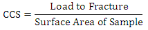
2.5. Bulk Density
The test specimens will be dried at 110°C for 12 hours to ensure total water loss. Their dry weights will be measure and recorded. They will be allowed to cool and then immersed in a beaker of water. Bubbles will be observed as the pores in the specimens will be filled with water. Their soak weights will be measure and recorded. They will then be suspended in a beaker one after the other using a sling and their respective suspended weights will be measure and recorded. Bulk densities of the samples can be calculated using the formula: 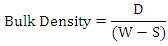 Where: D = Weight of dried specimen, S = Weight of dry specimen suspended in water, and W = Weight of soaked specimen suspended in air.
3. Results and Discussion
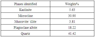
3.1. X-Ray Diffractrometry for the Clay Sample
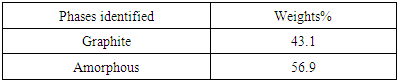
Figures 1 and 2 respectively shows the XRD result and SEM/EDX analysis of the raw clay sample. Tables 2 and 3 also respectively shows the XRD analysis results of the raw clay and spent graphite electrode samples. These show the various phases present in the raw clay sample. It can be seen from Table 2 that the overall feldspar contents of the raw clay samples is high (30.90% microcline and 18.22% Plagioclase Albite).Table 2. XRD result of the Ifon clay sample showing the quantity of phases
 |
| |
|
Table 3. XRD result of the Spent Graphite electrode sample showing the quantity of phases
 |
| |
|
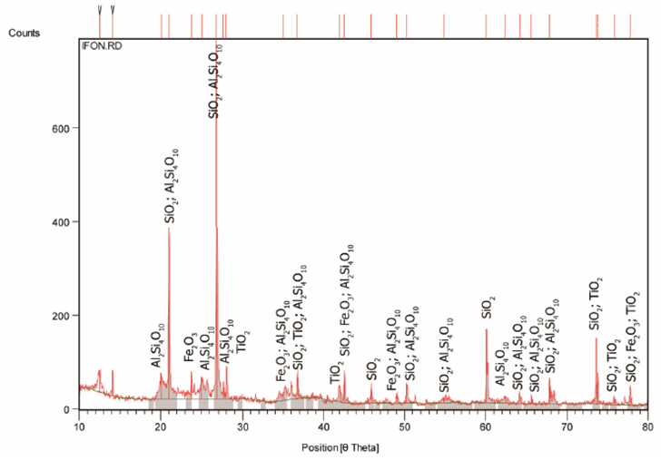 | Figure 1. X-Ray Diffraction Pattern (Phase Analysis) of Ifon Clay Sample |
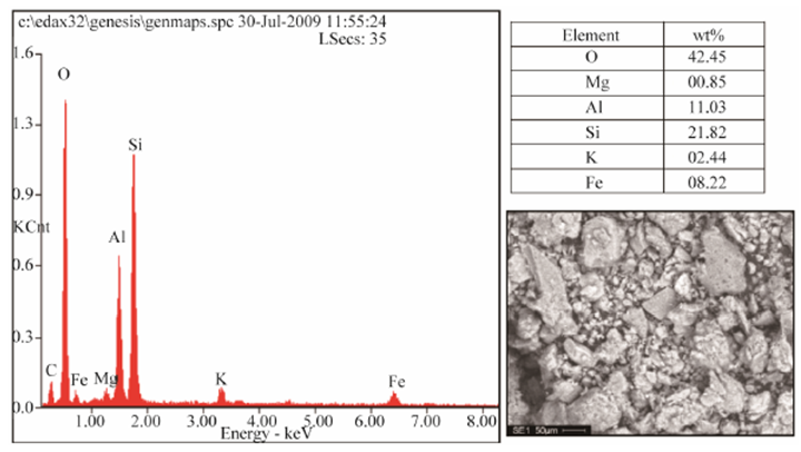 | Figure 2. Typical SEM/EDX of Ifon Clay Sample; Showing the Morphology of the Minerals and Its Chemical Composition |
It has been noted that feldspars favours liquid phase formation and densification at low temperature [15], this will disqualify the utilization of the clay in refractory (high temperature) applications except if subjected to serious purification process to reduce or eliminate the feldspar content and the fusion point of the fireclay increases [16].
3.2. Mechanical Properties of the Produced Refractory
3.2.1. Effect of Clay Content and Sintering Temperature on Bulk Densities
The results of the effects of clay content and sintering temperature on the bulk densities of produced clay bonded carbon refractory are presented in Figures 3a and 3b respectively. It is observed that for the 700°C sintered products (figure 3a), there appears to be an increase in bulk density of the produced clay bonded refractory with increase in the clay content. The increase in density with increase in clay content is obviously due to the high density of the raw clay in comparison with the spent graphite electrode samples. It is noted that for the 800°C and 900°C sintered refractory, there is deviation from the trend that was observed for the products sintered at 700oC. A decrease in bulk density with the increase in clay content from 40 to 50% was observed. Further increase in the clay content (above 50% clay) led to an increase in the bulk density. Generally, it could be summed that apart from the little deviation stated earlier, the bulk density of the samples increased with the clay contents. This can be explained that as the clay contents increase the fine particle size of the clay progressively filled up the voids between the coarser graphite particles, which results into increased bulk density as the voids are eliminated. This is also corroborated by the relationship shown in the Figure 4a. The plot of the effects of the sintering temperature on the refractory is shown in figure 3b. An increase in the bulk densities of refractory grades A, C and D (containing 40, 60 and 70% clay content) was observed with increase in sintering temperature. The refractory grade containing 50% clay content and sintered at 800°C is observed to have the least bulk density for this group of refractory.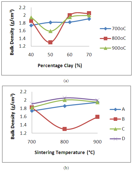 | Figure 3. Effect of (a) clay content and (b) sintering temperature on the Bulk densities of the clay bonded refractory |
3.2.2. Effect of Clay Content and Sintering Temperature on Apparent Porosity
The result of the effects of clay content and sintering temperature on apparent porosity of produced clay bonded spent graphite electrode refractory is presented in figure 4. It is observed that the porosity of the sample decreases with the increase in clay content (figure 4a). The increase in graphitic content of carbon based refractory has been reported to give rise to high porosity [17]. From Figure 4 (a), it is observed that the apparent porosity of the samples reduced with increase in the clay contents. This is as a result of fine clay particles filling up the voids between the more coarse graphite particles, thereby eliminating the existing pores. As the percentage content of the clay increased, the percentage content of graphite in the sample reduced, which means more fine clay particles are available to fill the pores between the more coarse carbon particles, hence the reduced porosity with increased percentage content of the clay.The effect of sintering temperature on the samples is presented in figure 4b. It is observed that the apparent porosity of samples A, B and C increased with increased sintering temperature, while that of sample D initially reduced as the sintering temperature increased from 700°C to 800°C. Further increase in the sintering temperature lead to increased apparent porosity. Generally it is observed that that the samples subjected to sintering temperature of 700°C averagely recorded low porosity levels compared to samples subjected to sintering temperature of 800°C and 900°C. The explanation for the increased porosity observed in samples A, B and C with increased sintering temperature is the more of the carbon contents of the samples are lost to oxidation with increased sintering temperature.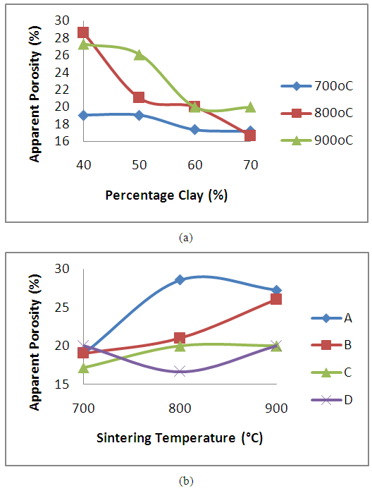 | Figure 4. Effect of (a) clay content and (b) sintering temperature on the apparent porosity of the clay bonded refractory |
The pores in the various samples sintered at the various temperatures is observed in the secondary electron images of the samples shown in Figure 8 (a), (b) and (c) to Figure 11 (a), (b) and (c).
3.2.3. Effect of Clay Content and Sintering Temperature on Young’s Modulus
The results of the effects of clay content and sintering temperature on the young modulus of the produced clay bonded carbon refractory were presented in Figures 5a and 5b respectively. The Young’s modulus which is a measure refractory’s rigidity is observed to increases with increase in weight percent of the clay content (figure 5a) in the clay bonded carbon refractory sintered at temperature 700°C, 800°C and 900°C. Refractory grades D (containing 70% clay content) were observed to have the highest young modulus irrespective of the sintering temperature. The improvement in the modulus as observed could be attributed to decrease in the amount of open porosity with increase in clay content as reported in figure 3a. Similar trend in young modulus result have been reported [12]. The results also confirmed that the addition of spent graphite electrode does not result in the improvement of the refractory rigidity. It was further observed from figure 7b that the modulus of refractory grades A, C and D (containing 40, 60 and 70% clay) increased with an increase in sintering temperature up to 800°C after which a decrease was observed. This suggests that Young’s modulus enhancement may not be achieved beyond 800°C for this grade of refractories.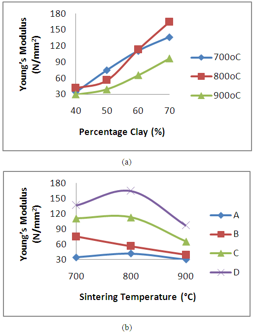 | Figure 5. Effect of (a) clay content and (b) sintering temperature on the young modulus of the clay bonded refractory |
3.2.4. Effect of Clay Content and Sintering Temperature on Absorbed Energy
Figure 6 presents the variation in absorbed energy as a result of the effects of clay content and sintering temperature on the produced refractory. It is observed from the figure 6a that as the clay content is increased (accompanied by a decrease in the spent graphite electrode content) the absorbed energy of the refractory increased for all the sintering temperatures worked on. (14.9, 6.17, 111.30%), (26.83, 82.81, 118.57%) and (33.38, 80.73, 95.17%) increment in the value of the absorbed energy was observed for the refractory sintered at temperature 700°C, 800°C and 900°C respectively. The increase observed in absorbed energy can be attributed to the decrease in porosity in the samples (as observed in figure 3a). It has been earlier discussed that the graphite’s average grain size coarser than that of the clay. This made the clay particles to fill the inter-particle voids between the graphite, thereby eliminating or reducing the voids. This is agrees with the findings of Ameh and Obasi [17]. It is also shown in figure 6b that the absorb energy reduced with increase in the sintering temperature. The refractory grades sintered at 700°C posses superior absorbed energy in comparison with grades sintered at 800°C and 900°C with refractory D (containing 70% clay content) yielding the highest absorbed energy value.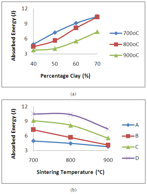 | Figure 6. Effect of (a) clay content and (b) sintering temperature on the absorbed energy of the clay bonded refractory |
3.2.5. Effect of Clay Content and Sintering Temperature on Cold Crushing Strength
The variation in values of the cold crushing strength of the samples subjected to sintering temperature of 700°C, 800°C and 900°C is reported in figure 7. It is generally observed that the cold crushing strength of the samples increased with increase in weight percentage of the clay content. The increase in strength of the refractory with increase in clay content (accompanied with reduction in weight percent of spent graphite electrolyte) results in increased matter content of the sample. This means that the refractory grades with high clay content have better load bearing capability than grades with low clay content [12]. Reductions in cold crushing strength of (20.74, 58.56 and 171.68%), (3.29, 82.10 and 132.09%) and (24.25, 80.83 and 147.18%) were obtained for the refractory grades subjected to sintering temperature of 700°C, 800°C and 900°C respectively. This is similar to the result earlier reported by Aramide, (2015) [14], on the effects of sintering temperatures on the phase development and mechanical properties of Ifon clay. Since it is the same Ifon clay that is made used of in the present work, it suggests the result is in order. The above behaviour suggests that the increased addition of graphite spent electrode is not favorable for cold crushing strength improvement. Figure 7b presents the effects of sintering temperature on the produced refractory. It is observed that there is a reduction in the cold crushing strength as a result of increase in the sintering temperature. The refractory grades sintered at 700°C posses superior strength in comparison with grades sintered at 800°C and 900°C with refractory D (containing 70% clay content) yielding the highest strength value.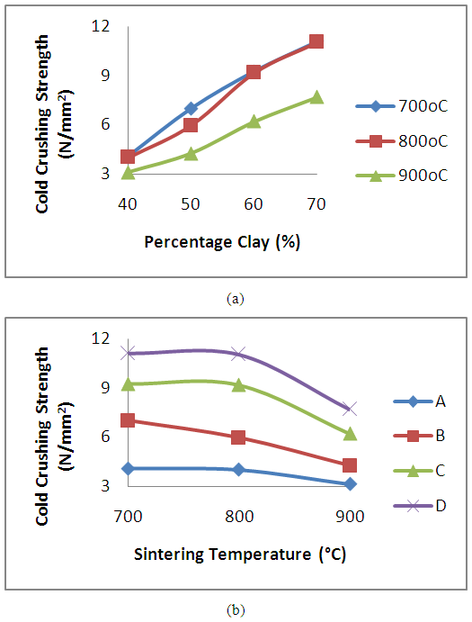 | Figure 7. Effect of (a) clay content and (b) sintering temperature on the cold crushing strength of the clay bonded refractory |
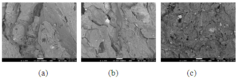 | Figure 8. Showing the Secondary Electron Image of Sample A: (a) sintered at 900°C, (b) sintered at 800°C (c) sintered at 700°C |
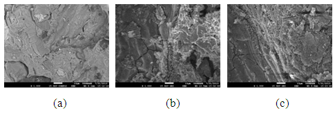 | Figure 9. Showing the Secondary Electron Image of Sample B: (a) sintered at 900°C, (b) sintered at 800°C (c) sintered at 700°C |
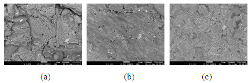 | Figure 10. Showing the Secondary Electron Image of Sample C: (a) sintered at 900°C, (b) sintered at 800°C (c) sintered at 700°C |
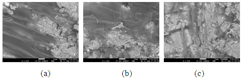 | Figure 11. Showing the Secondary Electron Image of Sample D: (a) sintered at 900°C, (b) sintered at 800°C (c) sintered at 700°C |
4. Conclusions
Clay bonded carbon refractory have been produced and properties investigated. From the results obtained, the following conclusions are drawn:● The bulk density of the samples generally with increase in the clay content. ● The porosity of the sample decreases with the increase in clay content ● The young modulus, absorbed energy and cold crushing strength of the samples increased with increase in weight percentage of the clay content.● The young modulus, absorbed energy and cold crushing strength of the samples reduced with increase in the sintering temperature. ● The sample sintered at 700°C possess superior mechanical properties.
References
| [1] | Aramide F. O. and Seidu S. O. Production of Refractory Lining for Diesel Fired Rotary Furnace Locally Sourced Kaolin and Potter’s Clay, Journal of Minerals and Materials Characterization and Engineering, 2013, 1, 75-79 |
| [2] | Onyeji, L. I. (2010). Analysis and Characterization of Nyikangbe clay, Chanchaga LGA Niger State. Journal of Minerals and Materials Characterization and Engineering, 55-62. |
| [3] | Chukwudi, B.C. (2008). “Characterization and Evaluation of the Refractory Properties of Nsu Clay Deposit in Imo State Nigeria”. Pacific Journal of Science and Technology. 9(2):487-494. |
| [4] | Waing, W. K., Shwe, W. H., & Kay, T. L. (2008). Study on the production of chromite refractory brick from local chromite ore. World Academy of Science, Engineering and Technology, 569-574. |
| [5] | Oyetunji A; Bankole, L.K. and Alhassan, A.O. (2009). Binding Characteristics of Mbushi and Ewekoro Clays of Nigeria in Foundry Moulding Sand. Global Journal of Engineering and Technology. 2, 4, 509-514. |
| [6] | Adondua, S. (1988). “Indigenous Refractory Raw Materials Base for Nigeria Steel Industries”. Journal of the Nigerian Society of Chemical Engineers (NSCHE). 7(2):322. |
| [7] | Obadinma, E.O. (2003). “Development of Refractory Bricks For Heat Treatment Facilities”. Journal of Science and Technology Research. 2(2):13-17. |
| [8] | Borode J. O., Onyemaobi O. O., Omotoyinbo J. A. (2000). Suitability of some Nigeria clays as refractory raw materials. Nigeria Journal of Engineering Management, 3, 14-18. |
| [9] | Ndaliman, M. B. (2007). refractory properties of termite hills under varied proportions of additives. AU J T, 159-162. |
| [10] | Oyetunji A. and Opaluwa I. (2012). Study the Compressive Strength of Produced Sand Cores Using Clay and Starch as Binder for the Casting of Aluminium Alloy T-Joint pipe. International Research Journal of Engineering and Technologies. Vol.4, Issue 3. Pp 50-60. Science Record Journals. |
| [11] | Musa U., Aliyu M. A., Mohammed I. A., Sadiq M. M. (2012). A Comparative Study on the Refractory Properties of selected Clays in North Central Nigeria. Academic Research International, Vol. 3, No. 1, pp 393-398. |
| [12] | Aramide F. O. and Oke S. R. (2014). Production and Characterization of Clay Bonded Carbon Refractory from Carbonized Palm Kernel Shell. Acta Tehnica Corviniensis – Bulletin of Engineering Tome VII, Fascicule 4, 133-140. |
| [13] | Hassan S. B., Aigbodion V. S. (2014). Effect Coal Ash on Some Refractory Properties Of alumino-Silicate (Kankara) Clay for Furnace Lining. Egyptian journal of basic and applied sciences 1, 107-114. |
| [14] | Aramide F.O. Effects of Sintering Temperature on the Phase Developments and the Mechanical Properties of Ifon Clay. Leonardo Journal of Sciences, Issue 26 (January-June) 2015, 67-82. |
| [15] | Reed J. S. (1995). Principles of Ceramic Proceedings, John Wiley and Sons, New York. |
| [16] | Carty W. M. and Senapati U. (1998), Porcelain-Raw Materials, Processing, Phase Evolution, and Mechanical Behavior, Journal of the American Ceramic Society, Vol. 81, No. 1, pp. 3-20. |
| [17] | Ameh, E. M. and Obasi, N. W. (2009). Effect of Rice Husk on Insulating Bricks Produced With Nafuta and Nsu Clays. Global Journal of Engineering and Technology, 2 (4), pp. 661-668. |

 Abstract
 Reference
 Full-Text PDF
 Full-text HTML