-
Paper Information
- Paper Submission
-
Journal Information
- About This Journal
- Editorial Board
- Current Issue
- Archive
- Author Guidelines
- Contact Us
International Journal of Metallurgical Engineering
p-ISSN: 2167-700X e-ISSN: 2167-7018
2015; 4(1): 12-23
doi:10.5923/j.ijmee.20150401.03
Effect of Annealing on Microstructure and Mechanical Behaviour of Cold Rolled Low C, High Mn TWIP Steel
 Abstract
 Reference
 Full-Text PDF
 Full-text HTML
N. K. Tewary , S. K. Ghosh , S. Chatterjee
Department of Metallurgy & Materials Engineering, Indian Institute of Engineering Science and Technology, Howrah, India
Correspondence to: S. K. Ghosh , Department of Metallurgy & Materials Engineering, Indian Institute of Engineering Science and Technology, Howrah, India.
| Email: |  |
Copyright © 2015 Scientific & Academic Publishing. All Rights Reserved.
In the present study, 10% and 30% cold rolled Fe-21Mn-3Si-3Al-0.06C TWIP steels have been annealed in the temperature range of 600-900°C for a short duration of 5 min. Optical and TEM microstructures reveal dislocations, micro-shear bands, deformation twins as well as interaction of dislocations and twins when deformed 10-30% by cold rolling. After annealing in the temperature range of 600-800°C, cold deformed austenite structures undergo recovery, whereas recystallisation occurs at 900ºC. It is noticed that the hardness, yield strength and tensile strength of the specimens increase whereas percentage elongation decreases as the amount of cold rolling reduction increases. Tensile test results show improvement in ductility and decrease in tensile strength of cold rolled samples subjected to annealing at 600°C. 30% cold rolling and annealing can be considered as an effective method to obtain submicron grain with an attractive combination of strength and ductility.
Keywords: Steel, Cold rolling, Annealing, Microstructure, Mechanical properties
Cite this paper: N. K. Tewary , S. K. Ghosh , S. Chatterjee , Effect of Annealing on Microstructure and Mechanical Behaviour of Cold Rolled Low C, High Mn TWIP Steel, International Journal of Metallurgical Engineering, Vol. 4 No. 1, 2015, pp. 12-23. doi: 10.5923/j.ijmee.20150401.03.
Article Outline
1. Introduction
- In the current century, advanced automobile researchers pay much attention on light weight vehicle which boosts fuel economy along with the reduction in emission of greenhouse gases. Substantial weight savings is possible only through extensive research on advanced high strength steel (AHSS). In order to fulfil this optimal combination, a variety of Advanced High Strength Steels (AHSS) has been developed such as Dual Phase (DP), Complex Phase (CP), Transformation Induced Plasticity (TRIP) and most recently, Twinning Induced Plasticity (TWIP) steels. Among the wide variety of recently developed steels, TWIP steel with light weight and high tensile strength along with adequate formability has become favourable to researchers due to its low stacking fault energy (SFE) and twinning effect [1]. High manganese TWIP steels have a good potential to manufacture such as structural reinforcements and energy absorption parts in the automotive industry. TWIP steel possesses a fully austenitic structure at room temperature mainly due to its high content of Mn which can be a range up to 17-30 wt% [2]. Below 17 wt%, it can’t suppress γ → α transformation [3]. Mn is not only an effective austenite stabiliser but also an element which increases SFE of TWIP steels. Apart from Mn, other ingredients such as C, Si, Al etc are added to this type of steel. In general, addition of Al increases SFE and strongly suppress γ → α transformation so that the formation of deformation twin is favoured. In contrast, Si decreases SFE and sustains γ → α transformation during cooling and deformation. The explanation for high strength and ductility of TWIP steels is still controversial. Some authors quantify this due to dynamic strain aging (DSA) mechanism [4], interpreted as the interaction between C–Mn bonds and mobile dislocations and some other justify it by its twinning mechanism [5]. During plastic deformation, deformation twinning plays a key role for this class of materials and the deformation mechanisms are closely related to the SFE of the austenitic phase. As the strain increases, the occurrence of twins reduces the mean free path of dislocations [6]. Cold working is generally applied to metals and alloys having high ductility [7]. The dislocation density as well as deformation twins increase with increasing amount of cold deformation in TWIP steel which results in improvement in strength achieved by dislocation-dislocation interaction as well as the interaction of dislocations with twin boundaries. However, greater deformation exhibits lowering ductility which can be improved by subsequent recovery treatment. It has been found that nano-scale mechanical twins have a thermal stability during recovery treatment [8]. The purpose of this paper is to get a comprehensive understanding of the extensive microstructural observation after recovery and partial recrystallisation. These include studies of the present investigated steel in primarily cold rolled and annealed conditions. Several characteristics features of recovery and recrystallisation are described. Attempt has been made to get a correlation between processing-microstructure and mechanical property and finally the properties of the developed steel have been compared with high strength automotive steels. The present study also pays attention to the stability of mechanical twins at elevated temperature.
2. Experimental
2.1. Materials Preparation
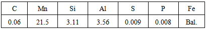
- A 25 kVA air induction furnace was used to manufacture the investigated steel with the chemical composition as listed in Table 1. After cropping the top section of the ingot containing shrinkage/pipes, the remaining ingot of 200 mm × 50 mm 50 mm size was hot forged down to 16 mm thick slab, which was further soaked at 1200°C for 40 minutes and subsequently rolled down to 8 mm thick plate in three passes with the finish rolling temperature (FRT) of 800C. The hot rolled and air cooled (AC) samples were solution treated at 1040°C for 1h to remove any inhomogeneities followed by water quenching to room temperature. Subsequently, the above solution treated samples were cold rolled by 10-30% reduction in thickness in several passes using a laboratory scale rolling mill. These samples were then suitably annealed in the temperature range of 600°C to 900°C for a fixed duration of 5 minutes followed by water quenching.
|
2.2. Experimental Procedures
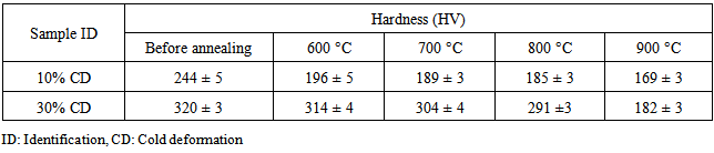
- The Vickers hardness (HV) values of the samples after cold deformation and annealing treatments were evaluated in a Vickers hardness tester (Leica-VMHT) using 2 kg load for 20s dwelling time and were shown in Table 2. ASTM E8M standard was followed to prepare sub-size tensile specimens having gauge length of 25 mm and the tests were carried out in an Instron 5900R testing machine using an extensometer with a crosshead speed of 0.5 mm/min. At least three specimens were tested and the average values were reported in Table 3. Both cold rolled and annealed samples were prepared by the conventional metallographic techniques and etched with 10% nital solution to reveal the microstructure of the specimens under the optical microscope (Carl Zeiss, AXIOVERT 40 MAT). For transmission electron microscopy, typical 3 mm diameter thin (~ 80 µm thick) discs were subjected to twin jet electro-polishing using a mixture of electrolyte of 90% acetic acid and 10% perchloric acid at a temperature of about 10-12°C. The thin electron transparent samples were examined in a high resolution transmission electron microscope (HRTEM) (Tecnai G2) at 200 kV operating voltage.
|
|
3. Results
3.1. Microstructure Evolution
- Figure 1(a) shows the optical micrograph of hot rolled - air cooled sample depicting equiaxed austenite grains with some annealing twins (AT). Ferrite phase of brighter contrast is apparent along the grain boundary of austenite grain. Some inhomogenities /intergranular carbide precipitates may be segregated with the above ferrite phase. Similar types of microstructural constituents were reported earlier in case of dual phase TWIP steel [9]. Figure 1(b) shows the optical micrograph of hot rolled and solution treated (1040C, 1h) specimen revealing fully austenitic structure with annealing twins. It may be mentioned that the above solution treatment is essential to remove the heterogeneities associated with the hot rolling operation. Figure 1(c) shows the optical microstructure of 10% cold deformed (CD) sample which exhibit both annealing twin (AT) and deformation twins (DT). 30% cold deformed sample reveals predominantly higher amount of deformation twins (Fig. 1(d)). In this context, it is obvious that increasing amount of deformation leads to more deformation twins in structure. It is important to note that deformation/mechanical twins are finer compared to annealing twins and they are activated within grains and are blocked by grain boundaries.
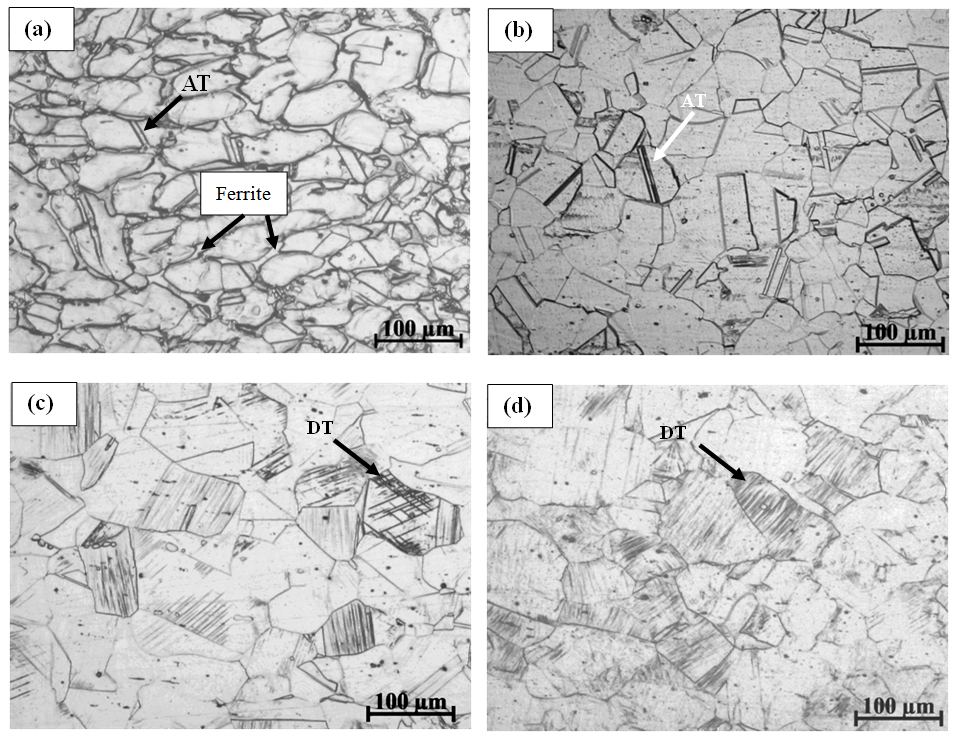 | Figure 1. Optical micrograph of (a) hot rolled – air cooled with 800C FRT, (b) hot rolled and solution treated (1040C, 1 h) specimen, (c) 10% cold deformed sample shows annealing twin (AT) and deformation twins (DT) and (d) 30% cold deformed sample reveals higher amount of deformation twin |
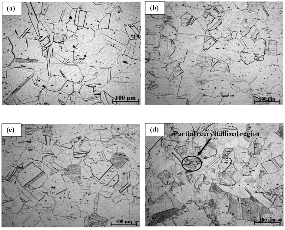 | Figure 2. Optical micrograph of hot rolled - air cooled and 10% cold deformed samples subjected to annealing for 5 minutes at (a) 600°C, (b) 700°C, (c) 800°C and (d) 900°C |
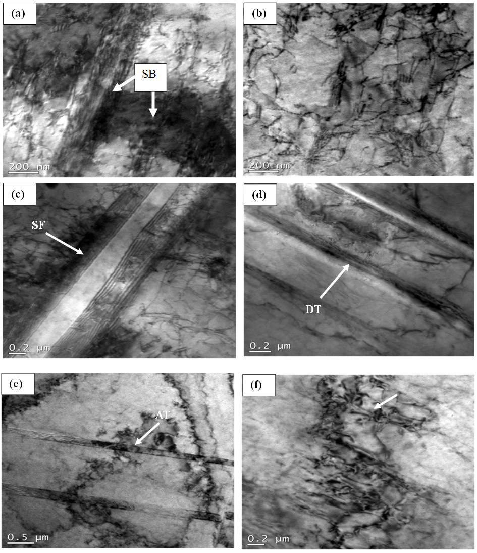 | Figure 3. TEM bright field (BF) micrograph of 10% cold rolled and annealed (900°C, 5 min.) specimen showing (a) onset of recovery, (b) dislocation cell structure indicating progress of recovery, (c) twin-stacking faults (SFs) interaction, (d) deformation twins (DT), (e) recovered cellular region with annealing twins (AT) and (f) partially recrystallised submicron grain (denoted by arrow) along the deformed austenite grain boundary |
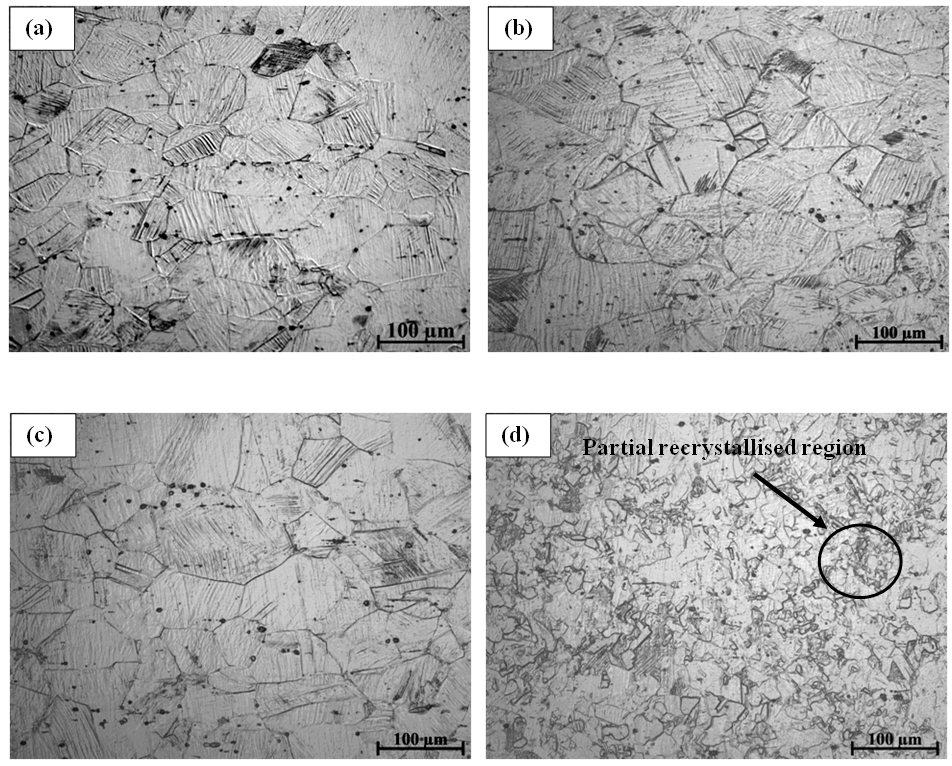 | Figure 4. Optical micrograph of hot rolled - air cooled and 30% cold deformed samples subjected to annealing for 5 minutes at (a) 600°C, (b) 700°C, (c) 800°C and (d) 900°C |
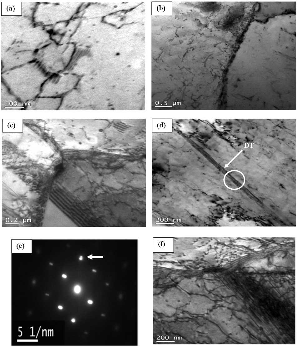 | Figure 5. TEM BF micrograph of 30% cold rolled and annealed (900°C, 5 min.) specimen showing (a) partially recrystallised submicron austenite grain, (b) dislocation pile up along the austenite grain boundary, (c) stacking faults (SFs), (d) deformation twin (DT), (e) SAED pattern with the twinned spot (denoted by arrow) confirming DT and (f) twin-stacking faults (SFs) interaction at 900°C |
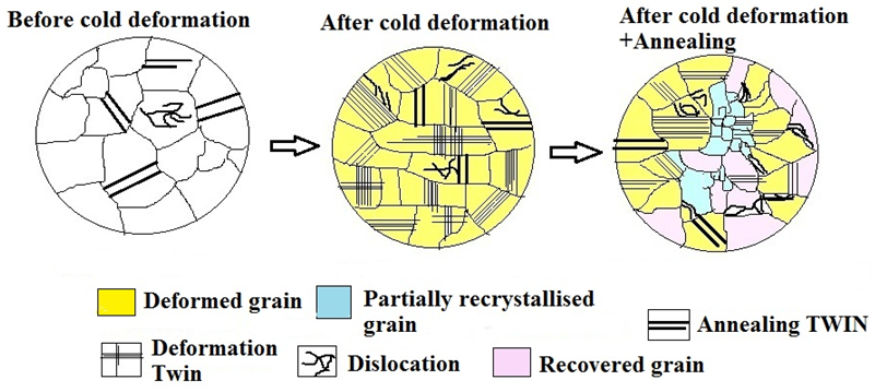 | Figure 6. Schematic illustration showing microstructural changes before and after cold rolling and annealing |
3.2. Mechanical Property
3.2.1. Hardness
- Table 2 and Fig. 7 show Vickers hardness values (HV) of 10% and 30% cold deformed samples before and after annealing treatment. It has been already noticed from previously described microstructural evolution that by annealing treatments at 600°C to 900°C for 5 minutes recovery and partial recrystallisation occur and thereby hardness values decrease with the increase of annealing temperature. The slope of the hardness curve decreases prominently after annealing at 700°C and it is more predominant in 30% CD than 10% CD samples. It can be mentioned that recovery is more prominent than recrystallisation within the temperature range of 600°C to 700°C. At 900°C, the hardness values are minimum for both 10% and 30% CD samples. This can be attributed to the fact that the softening is now dominated by recrystallisation instead of recovery.
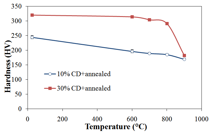 | Figure 7. Hardness versus temperature plots of 10% and 30% cold deformed specimens subjected to annealing at different temperatures for 5 minutes |
3.2.2. Tensile Results
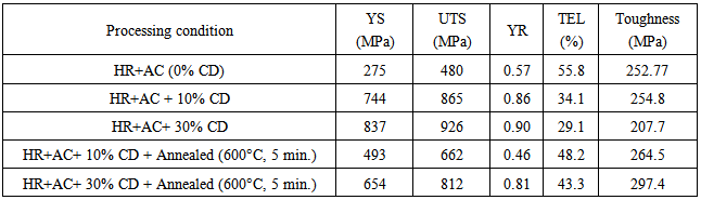
- Table 3 summarises the tensile test results of hot rolled and air cooled specimens as well as in different cold deformed conditions before and after annealing treatments. It is noticed that good combination of high tensile strength and total elongation (TEL) can be achieved by cold rolling. It is clearly observed that the yield strength (YS) and ultimate tensile strength (UTS) of the specimens increase with the increasing amount of cold deformation which is in line with the earlier reports [14]. The increasing trend of strength properties has been found to be more pronounced when the specimen was given 30% cold deformation. This type of behaviour is attributed to the strain hardening phenomenon owing to interaction among dislocations and twins generated by cold deformation [15]. After recovery during annealing at 600°C for 5 minutes, the ductility has been improved (48% for 10% CD and 43% for 30% CD specimens) with decrease in tensile strength (662 MPa for 10% CD and 812 MPa for 30% CD specimens). In the mean time, the deformation twins induced by cold rolling remain during annealing at 600C and expected to overcome the loss of strength after annealing. Figure 8 shows comparison of results obtained from the tensile testing of the experimental steels. Figures 8(a) and (b) show that 30% cold deformed sample has the maximum YS and UTS among all samples. It is evident that with the increase in percentage of cold deformation strength value increases. Figure 8(c) reveals that after annealing at 600°C for 5 minutes the ductility is restored or increasing. Figure 8(d) indicates that the maximum toughness is achieved in case of 30% cold rolled and annealed (600°C for 5 min.) specimen. Low yield ratio (YR) (0.46-0.81) (Table 3) along with high strength, obtained after cold deformation and annealing, also ensures high energy absorption capacity of the steel (toughness) which improves the reliability of the steel during operation in service.
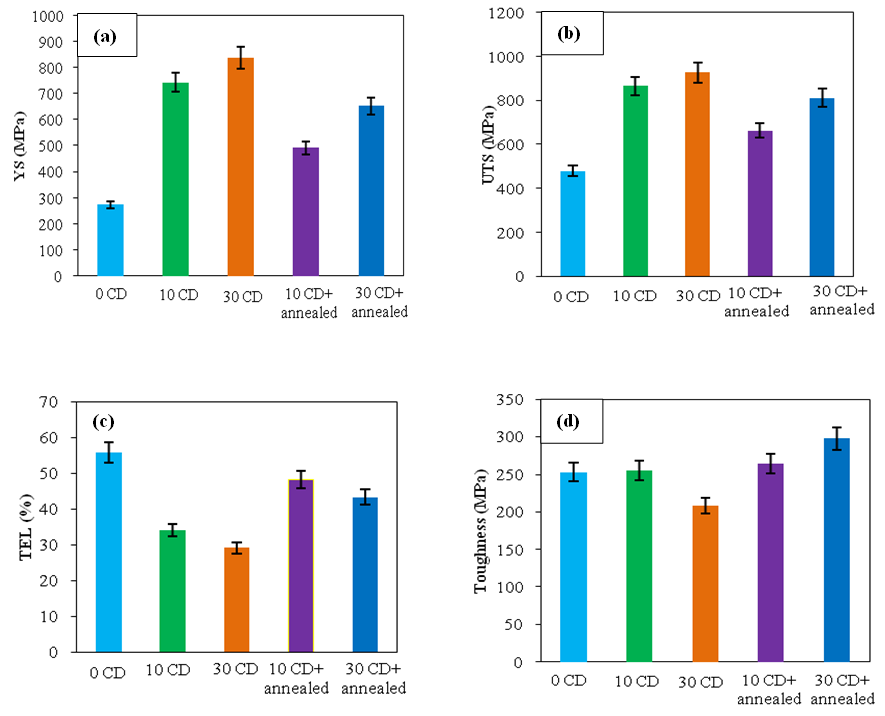 | Figure 8. Comparison of tensile test results (a) Yield Strength (YS), (b) Ultimate Tensile Strength (UTS), (c) Total elongation (TEL) and (d) Toughness of cold deformed and annealed (600°C, 5 min.) samples |
4. Discussion
- The microstructure after hot rolling consists of austenite and ferrite (Fig. 1(a)) which have been elongated through hot rolling. This duplex microstructure is plausibly caused by Al, which stabilised the ferrite at the high temperature at which the hot rolling was performed. Mn segregation frequently occurs for high Mn containing steel and has an influence on the microstructural evolution [17]. Mn is an austenite stabiliser and, therefore, the ferrite could preferentially form in a Mn-lean region. The optical micrographs of 10% and 30% cold deformed samples comprise fully austenitic structure with annealing and deformation twins. It is evident that density of deformation twin increases significantly with the increasing degree of deformation (Fig. 1). It is important to note that the present steel which has been deformed under cold rolling at room temperature, a part of the energy of deformation is stored as the increase in the dislocation density and the balance is consumed in forming deformation twins (Fig. 3). It is known that recovery of deformed steel is a process that takes place prior to recrystallisation during annealing and it is generally used to recover the properties up to some satisfactory level which dropped during deformation [18]. During recovery, dislocations annihilate or rearrange themselves in configurations of lower energy [19]. After annealing in the lower temperature range of 600-800°C, microstructure comprises a mixture of twinned deformed grains and dislocation-free recovered grains for both 10% and 30% CD samples. Annealing at higher temperature of 900°C leads to the formation of a mixture of partially recrystallised and deformed areas with imperfections like stacking faults, annealing and deformation twins (Figs. 3 and 5). The optical micrographs presented in Figs. 2(d) and 4(d) reveal that recrystallisation starts in austenite grain boundary region, resulting in the high anisotropy of the microstructure [10]. High temperature annealing results in relatively thick and distinct grain boundaries along with the low dislocation density inside the submicron grains (Figs. 3(f) and 5(a)). This could be attributed to the recovery process associated with the absorption of dislocations by grain boundaries [20]. It has been noticed that the recrystallised area of 30% CD and annealed (900°C) sample is more than that of 10% CD and annealed (900°C) sample (Fig. 2(d) vis-à-vis Fig. 4(d)). In this context, H. S. Zurob et al [21] reported that the driving force for recrystallisation is the stored energy of deformation, often expressed as:
 | (1) |
 | (2) |
 | (3) |
 | (4) |
 | (5) |
|
5. Conclusions
- Based on the above results, the major conclusions can be derived as follows: 1. Optical and TEM micrographs of 10% and 30% cold deformed samples exhibit dislocations, micro-shear bands, nano-scale (<100 nm) deformation twins as well as interaction of dislocations and twins. 30% cold deformed sample reveals higher amount of deformation twins than those of 10% cold deformed specimen. 2. Microstructural examination of cold deformed samples revealed recovery during annealing at 600°C - 800°C for 5 minutes. However, annealing at 900°C showed partially recrystallised submicron grain with deformation twins. 3. The presence of deformation twin even at 900ºC indicates its thermal stability in the microstructure which could be related with the sluggish rate of recrystallisation due to relatively low SFE of about 24 mJ/m2. 4. Hardness values dropped significantly from 244 HV to 169 HV and from 320 HV to 182 HV for10% and 30% cold deformed samples, respectively after annealing at 600-900°C.5. Enhancement in ductility (34-48% for 10% and 29-43% for 30% cold rolled samples) and decrease in tensile strength (865-662 MPa for 10% and 926-812 MPa for 30% cold rolled samples) are achieved after annealing at 600°C. 6. 30% cold rolling and annealing is the effective method to obtain submicron grain with an attractive combination of strength and ductility.
ACKNOWLEDGEMENTS
- The authors gratefully acknowledge the financial support provided by the Centre of Excellence (COE), TEQIP-II, IIEST, Shibpur, India for publication in the present journal.