-
Paper Information
- Next Paper
- Previous Paper
- Paper Submission
-
Journal Information
- About This Journal
- Editorial Board
- Current Issue
- Archive
- Author Guidelines
- Contact Us
International Journal of Metallurgical Engineering
p-ISSN: 2167-700X e-ISSN: 2167-7018
2013; 2(2): 214-220
doi:10.5923/j.ijmee.20130202.13
Thermo-Mechanical Axial-Torsion Testing to Assess Workability – Modeling Using Finite Element Method and Experimental Validation
 Abstract
 Reference
 Full-Text PDF
 Full-text HTML
Utpal Borah, Diptimayee Samantaray, Shaju K. Albert, A. K. Bhaduri, T. Jayakumar
Metallurgy & Materials Group, Indira Gandhi Center for Atomic Research, Kalpakkam, 603102, India
Correspondence to: Utpal Borah, Metallurgy & Materials Group, Indira Gandhi Center for Atomic Research, Kalpakkam, 603102, India.
| Email: |  |
Copyright © 2012 Scientific & Academic Publishing. All Rights Reserved.
Owing to the inevitable multiaxial state of deformation kinematics and stresses in bulk metal forming processes, evaluation of workability calls for materials testing using combined axial and torsion tests. A high temperature combined axial and torsion testing system (ATTS) was developed in IGCAR for assessing workability of various materials under multi-axial state of stress and deformation conditions up to 1300 °C. In this paper, results from finite element modeling of axial torsion tests and seamless tube extrusion are presented. Combined torsion-compression tests would represent the state of stress and extent of deformation in tube extrusion more closely than axial torsion with tension or pure torsion tests.
Keywords: Axial-Torsion Testing, Finite Element Method, Tube Extrusion, Workability, Stress Triaxiality, Torsional Ductility
Cite this paper: Utpal Borah, Diptimayee Samantaray, Shaju K. Albert, A. K. Bhaduri, T. Jayakumar, Thermo-Mechanical Axial-Torsion Testing to Assess Workability – Modeling Using Finite Element Method and Experimental Validation, International Journal of Metallurgical Engineering, Vol. 2 No. 2, 2013, pp. 214-220. doi: 10.5923/j.ijmee.20130202.13.
Article Outline
1. Introduction
- In bulk metal forming processes, the billet experiences multi-axial state of stress and strain and workability of materials needs to be evaluated under multiaxial state of stress. Workability is generally defined as the ability to form a material within the load capacity of the available tooling and equipment without the introduction of failure or development of undesirable microstructure[1]. Evolution of microstructure during forming would depend on the kinematics and stress state in the material apart from temperature. Optimization of complex forming processes to produce defect-free parts with desirable microstructure calls for control of deformation parameters like strain rate, strain path, stress and temperature. Workability of the material is sometimes exceeded in the forming processes leading to undesirable flaws in the formed part and in some instances to fracture. Fracture controlled failure in relatively uniform deformation or shear localization controlled failure in localized failure plastic deformation may lead to such failures[2]. Hence, understanding of the behavior of materials under conditions similar to actual metal forming processes is essential for proper evaluation of workability.Thermo-mechanical axial torsion testing imparts multi-axial state of stress and strain in the specimen up to a substantially large strain level. Numerical modeling for evaluation of the kinematics, stress state and temperature profile and history would assist in proper design of multi-axial deformation processing experiments to assess workability of materials. This work aims at evaluating the kinematics and stress state of viscoplastic axial-torsion deformation in both compression and tension modes usingFinite Element Method (FEM). The next section discusses about thermo-mechanical axial torsion testing. Section 3 discusses about FEM modeling of seamless tube extrusion and axial torsion tests. Results are discussed in Section 4 followed by conclusions in Section 5.
2. Thermo-mechanical Axial Torsion Testing
- A high temperature combined axial and torsion testing system (ATTS) was developed in Metal Forming & Tribology Programme (MFTP) in Indira Gandhi Center for Atomic Research (IGCAR) for assessing workability of various materials under multi-axial state of stress and deformation conditions up to 1300 °C. The machine has torque capacity of 1000 N-m up to maximum rotational speed of 850 RPM and axial load capacity of ±100 kN up to maximum linear speed of 1.5 m/s. The digitally controlled ATTS can carry out controlled thermo-mechanical tests under concurrent torsion and axial (tension/compression), sequential torsion and axial, pure torsion, compression and tension in twist, torque, axial load and stroke control. The ATTS is fitted with a 6 kW induction heating system along with a controlled water jet based specimen quenching system.The machine holds the specimen in a hydraulic grip which can exert different clamping loads up to 120 kN on the specimen shoulder by varying the hydraulic fluid pressure. The machine is of modular design with independent actuators for torsion and axial loading of the specimen. The axial load is imparted using a double acting servo hydraulic actuator through the lower grip. A hydraulic motor mounted on the movable top crosshead imparts torsional load on the specimen through servo hydraulic valves up to 850 revolutions. This is a unique feature of the machine which enables imparting torsional load up to failure of the specimen thereby leading to evaluation of torsional ductility of materials. The angle of rotation is measured by an angular encoder with resolution of 0.036 degree. Conventional LVDT is used for measurement of axial stroke and a multi-axial load cell is used for measurement of torque and axial load simultaneously. Axial torsion tests were carried out on 316L stainless steel using this machine for validation of the FEM model for axial torsion tests.
3. Thermo-mechanical Fem Modeling
3.1. Seamless Tube Extrusion
- An axisymmetric FEM model was developed using the general purpose FEA code ABAQUS v6.10 and executed for extrusion of an annular billet of 172 mm outside diameter (OD), 80 mm inner diameter (ID) and 600 mm length to a seamless tube of 114 mm OD with 20 mm wall thickness (WT). The OD and WT reduction ratio were 1.51 and 2.3 respectively. As both the billet and tube are of circular shape, an axisymmetric FEM model would suffice for this process. Bilinear reduced integration elements were used for the billet. The die and mandrel were modeled as rigid bodies. Extrusion was carried out at ram speed of 250 mm/s. In view of inevitable severe distortion of the elements due to large deformation in extrusion, Arbitrary LagrangianEulerian (ALE) adaptive meshing was used to preserve the desired quality of the FE mesh. The coefficient of friction between the billet and tool surfaces was taken as 0.1. The mandrel was held fixed coaxially inside the die and downward stroke applied at the top surface of the billet thereby pushing the billet through the die.
3.2. Axial-Torsion Testing
- Various authors have proposed multiple plasticity models for torsional deformation[2-7]. However, literature on numerical modeling of thermo-mechanical axial torsion deformation in steels is scarce. Although the geometry of the axial torsion specimen is axisymmetric, the process is not amenable to conventional axisymmetric FEM modeling due to the torsional loading. The generalized axisymmetric element formulation in ABAQUS allows for an additional degree of freedom to apply torsional loading to the axisymmetric elements about the axis[10, 11]. These elements in fully integrated bilinear form, designated as CGAX4, were used in the FE models of the following tests:(i) Pure torsion at 1rpm speed: gauge diameter = 15 mm and gauge length =78.2 mm, fillet radius = 25 mm, one revolution.(ii) Pure torsion at 1rpm speed: gauge diameter = 10 mm and gauge length =10 mm, fillet radius = 5 mm, one revolution.(iii) Torsion at 1rpm with compression at 0.083 mm/s: gauge diameter = 10 mm and gauge length =10 mm, fillet radius = 5 mm, one revolution, 5 mm stroke.(iv) Torsion at 1rpm with tension at 0.083 mm/s: gauge diameter = 10 mm and gauge length =10 mm, fillet radius = 5 mm, one revolution, 5 mm stroke.Elasto-plastic FEM modeling was carried out for room temperature torsion testing of 316L Stainless Steel conforming to test case (i). The model was validated with experimental torsion test data generated by the ATTS. Subsequently, elasto-viscoplastic FEM modeling of axial-torsion tests were carried out using this validated FEM model for tests cases (ii) to (iv). Strain rate dependent material properties of 0.25C steel in austenitic state at 1100 deg C as given in Ref.[12] were used as constitutive data for the FE models.
4. Results and Discussions
- The FE mesh and deformed configurations of seamless tube extrusion, pure torsion, torsion with compression and torsion with tension are shown in Figs. 1, 2, 3 and 4 respectively. The stresses and deformation aremaximum in the conical die region during tube extrusion due to the normal and tangential forces exerted during conversion of billet into tube.The stresses get released as the tube exits the die. In pure torsion, the stresses and deformation are maximum at the surface of the specimen. However, imposition of axial stroke in the form of compression or tension, substantially reduce the gradient of stresses and strains from centerline to the surface of the specimen.
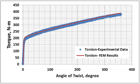
4.1. Torque-Twist Curves in Axial Torsion
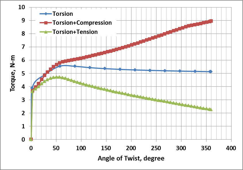
- Comparison of torque-twist data from the FEM model for test case (i) with experimental data from room temperature torsion test of 316L stainless steel is shown in Fig. 5. The calculated torque-twist data matches very closely with the experimental data thereby validating the FEM model.The torque-twist curves for the tests cases (ii) to (iv) generated by FEM are shown in Fig. 6. When simultaneous compression is imparted along with torsion, the torque increases as compared to that in pure torsion, indicating increase in material resistance. This is due to the triaxial compressive state of stress generated in the gauge section and increase in diameter of the gauge section. However, the torque reduces substantially upon simultaneous application of tensile stroke along with torsion due to necking and generation of triaxial tensile state of stress in the gauge section.
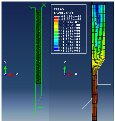 | Figure 1. Tube Extrusion – Stress Triaxiality distribution |
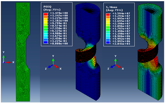 | Figure 2. Pure Torsion – FE Mesh, Equivalent Plastic Strain and von-Mises Stress distribution |
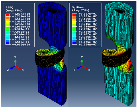 | Figure 3. Torsion with Compression – Equivalent Plastic Strain and von-Mises Stress distribution |
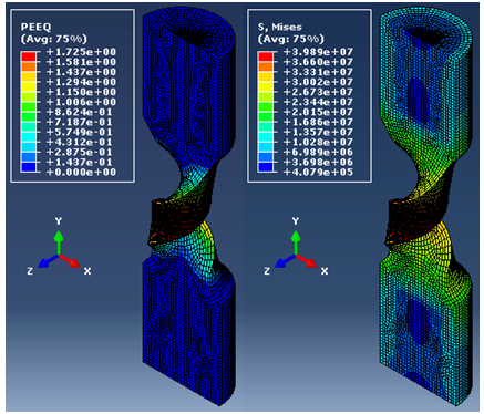 | Figure 4. Torsion with Tension – Equivalent Plastic Strain and von-Mises Stress distribution |
 | Figure 5. Experimental Validation of Axial Torsion FEM Model |
 | Figure 6. Torque-Twist Curves in Axial-Torsion from FEM model |
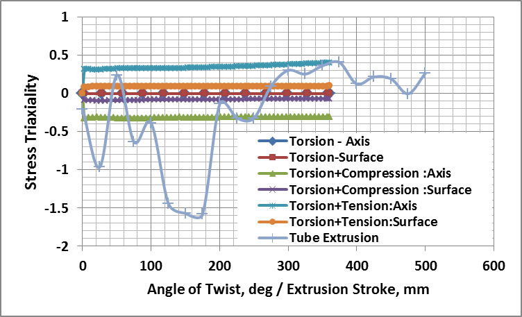 | Figure 7. Evolution of Stress Triaxiality in Seamless Tube Extrusion and Axial Torsion Testing |
4.2. Stress Triaxiality
- Stress triaxiality distribution during seamless tube extrusion for a ram stroke of 500 mm is shown in Fig. 1. Stress triaxiality was defined as the ratio of hydrostatic stress to von-Mises effective stress. To evaluate the history of stress state of a material point in the billet throughout the tube extrusion process, stress triaxiality at a typical point near to the die entry side of the billet were extracted and plotted against the extrusion stroke. Stress triaxiality was also calculated for the axial torsion tests on the axis and surface along the centerline of the gauge section. The evolution of stress triaxiality in tube extrusion and axial torsion are shown in Fig. 7. In the extrusion, stress triaxiality is compressive in the die zone (identified by the dotted box) and transforms into tensile as the tube exits the die. This quantitatively confirms existence of triaxial state of stress in tube extrusion.In pure torsion, stress triaxiality is negligible in the gauge section as the predominant deformation mode is shear. However, in axial torsion with compression, there exists a state of compressive stress triaxility in the gauge section which is maximum at the axis and propagates to the surface. In axial torsion with tension similar trend of tensile stress triaxility exists. The distribution of the stress triaxiality in the gauge section can be made uniform by suitably selecting the axial strain rate to be applied along with the torsion stroke.Thus, axial torsion tests would represent the state of stress and extent of deformation in tube extrusion more closely than pure torsion or axial tests.
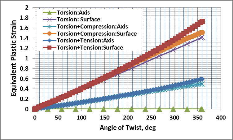
4.3. Effective Strain Rate and Equivalent Plastic Strain in Axial Torsion
- Evolution of effective strain rate and equivalent plastic strain in the gauge section during axial torsion tests are shown in Figs. 8 and 9 respectively. In pure torsion, there is nil equivalent plastic strain at the axis and it increases linearly with radius with the maximum occurring at the surface. Effective strain rate is also negligible at the axis and maximum at the surface. Thus a large gradient of kinematic parameters of deformation exists along with that of the stresses. This would lead to inhomogeneous distribution of various dynamic microstructural parameters.
 | Figure 8. Evolution of Equivalent Plastic Strain in Axial Torsion Testing |
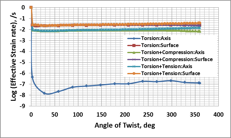 | Figure 9. Evolution of Equivalent Strain Rate in Axial Torsion Testing |
5. Conclusions
- Detailed FEM analysis of seamless tube extrusion and axial torsion tests were carried out in this work. The FEM model for axial torsion tests compared very closely with experimental results. In the die zone of tube extrusion compressive stress triaxiality exists which gets converted into tensile as the tube exits the die. Axial torsion tests with simultaneous compression would represent the state of stress and extent of deformation in tube extrusion more closely than axial torsion with tension or pure torsion tests.