K. M. Banks1, A. S. Tuling1, B. Mintz2
1Industrial Metals and Minerals, University of Pretoria, SA
2City University, London, UK.
Correspondence to: K. M. Banks, Industrial Metals and Minerals, University of Pretoria, SA.
| Email: |  |
Copyright © 2012 Scientific & Academic Publishing. All Rights Reserved.
Abstract
This paper reviews recent work concerning improvements to the hot ductility test to simulate straightening during continuous casting of steel slabs and billets. Various thermal paths were tested for their suitability in assessing the likelihood of transverse cracking in a variety of mostly microalloyed steels. For non-Ti steels with reasonably high Mn contents, the simple procedure of reheating to dissolve all the microalloying additions, followed by cooling to the test temperature is adequate. However, tests that include in-situ melting, followed by primary rapid cooling in the mould and foot-rolls and slow secondary cooling are generally recommended. Whilst the inclusion of thermal oscillations to simulate slab-roll contact improves accuracy, they are only recommended for steels with high transformation-start temperatures. The following systematic studies on as-cast hot ductility were performed using the improved cycle method: i) The influence of Ti in low C-Nb steel slabs - here, the ductility decreased markedly with the addition of Ti using simple tests. However, when the improved thermal cycle was applied, Ti additions were found to be beneficial up to a Ti:N ratio of at least 7.5:1. ii) The influence of V and N content in Nb-Ti peritectic steel slabs – the ductility improved when V was added to Nb-Ti steels and was attributed to a delay in precipitation and a decrease in fine particle fraction. To avoid transverse cracking in these steels containing high N, hypo-stoichiometric additions of Ti are required. iii) The influence of high N content in a range of medium C microalloyed billets - it was shown that Ti additions to V- or Al- containing grades, although beneficial at low N levels, are detrimental to hot ductility probably due to a higher precipitate volume fraction. Ti-high B-high N steels produced the poorest hot ductility. Low total B content and near stoichiometric Ti:N ratios significantly improved ductility by reducing the potential for harmful BN and AlN precipitation. Grades containing moderate amounts of V resulted in good ductility due to the suppression of precipitation. Thermal modelling and industrial observation indicated that corner temperatures of microalloyed steel slabs should be below the Ae3 during unbending to prevent corner cracking. Conversely, high unbending temperatures corresponding to the upper portion of the ductility curve should be aimed for in billet casting.
Keywords:
Transverse Cracking, Hot Ductility, Microalloyed Steels
Cite this paper: K. M. Banks, A. S. Tuling, B. Mintz, Improved Simulation of Continuous Casting to Predict Transverse Corner Cracking in Microalloyed Steels, International Journal of Metallurgical Engineering, Vol. 2 No. 2, 2013, pp. 188-197. doi: 10.5923/j.ijmee.20130202.10.
1. Introduction
The simple hot tensile test has long used to estimate the likelihood of transverse cracking occurring during the continuous casting of microalloyed steels. Although an over-simplification of the industrial continuous casting operation, this test successfully ranked C-Mn-Al, C-Mn-Nb and C-Mn-V steels in order of their susceptibility to transverse cracking. More sophisticated tests for direct application to commercial billet and slab casting operations are reviewed here[1-5].The original hot tensile test consisted of heating to sufficiently high temperatures (1250-1300℃) to dissolve all carbonitride and AlN precipitates and generate a coarse grain size to approximate the as-cast microstructure. The tensile specimen was then cooled at a constant, average cooling rate experienced by the strand from the melt to the test temperature, this being taken as typically 60℃/min for a 220mm thick strand. For these conditions a reduction-in-area, RA, above 35-40% was necessary to prevent cracking[6,7].A 2-D temperature model[8] showed that the surface of the strand cools rapidly in the mould after pouring and reaches a temperature trough at the foot-rolls. As the strand moves down the caster, the surface temperatures initially rise again due to the hotter interior but eventually fall slowly during secondary cooling. When the hot strand is in contact with the colder guide-rolls, the surface temperature oscillates significantly for a short period.Cooling at the corners region is the fastest and, due to geometry, cooling rates in billets are higher than in slabs. Depending on the severity of the cooling pattern, the temperature in the corner region can fall into the austenite-ferrite transformation zone at the end of primary cooling, thereby refining the grain size and promoting precipitation of carbides and nitrides. A small amount of transformation is detrimental to ductility since the strain concentrates in the thin ferrite films, whilst a large, soft ferrite fraction is beneficial since much more strain can be absorbed during unbending.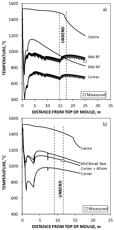 | Figure 1. 2-D continuous casting temperature model for a) steel C6, 240 x 900mm2 strand: speed = 1m/min, radius = 10m, b) steel M5, 140mm2 billet: speed = 2.3m/min, radius = 7m. BF = broad face, NF = narrow face[8] |
The thermal path selected for the tensile test approximates a specific position in the strand. The most relevant thermal path to simulate corner cracking is open to question and accounts for the wide range of cooling rates used (10-1200℃/min)[7]. Although cracks originate at oscillation marks on the surface, the location to which they propagate is likely to be below the surface, where the chill, fine-grained zone merges into the coarse, columnar region.
2. Experimental
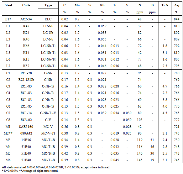
The steel compositions studied, together with their calculated Ae3 temperatures[9], are shown in Table 1 and include low C, peritectic C and medium C microalloyed steels. Additional results on medium C-Ti-B steels, not published previously, are also briefly discussed. “Peritectic” here refers to the C content but may actually be non-peritectic due to other additions. Various cooling profiles were applied using a Gleeble 1500D, figure 2, to determine hot ductility behaviour. A typical unbending strain rate of 3x10⁻³s-1 was used in all tests.Average cooling rate – cycles A,B,C: In figure 2a, cycle A represents the older test method, where the specimen was reheated to 1300℃ and cooled at a constant cooling rate of 300℃/min. to the test temperature. In cycle B, specimens were in-situ melted and directly cooled at 300℃/min. to the test temperature.In cycle C, specimens were melted and cooled at a relatively fast secondary cool rate of 24℃/min directly to the test temperature.Primary & secondary cooling–cycles D,E: Cycle D approximated the thermal path at the sub-surface corner region of slabs. This quasi-industrial cycle, figure 2b, included in-situ melting, initial cooling at 600℃/min to the end of the foot-rolls, a temperature rise due to heating of the surface from the molten core and subsequent secondary cooling at 12℃/min to the test temperature. The corner temperatures at the end of initial cooling in these tests was chosen to fall in the austenite region, although these may be lower depending on cooling severity. Cycle D for simulating 140mm2 billet casting included faster speeds and faster secondary cooling rates (2.2m/min, 24oC/min), figure 2c.Cycle E was similar to cycle D for slabs but included a number of thermal oscillations to simulate contact of the strand surface with guide-rolls on the broad faces.Table 1. Composition of steels tested
 |
| |
|
3. Results and Discussion
Influence of thermal cycleFigure 3 shows the effect of thermal cycle on the RA value of various steels at 800oC. Generally, melt cycle B showed inferior ductility in all steels when compared to reheated cycle A. The poor ductility found in melted and directly cooled tests was observed previously by Mintz et al[7] and indicated that a more accurate simulation of continuous casting was required. This is especially true for Ti-microalloyed steels, where good ductility experienced under industrial (melted) conditions must be replicated[10-12].In figure 3a, the RA values for steel E1 after cycles B-D are similar, but significantly lower than that found after cycle E. The improvement in hot ductility of steel E1 when cycle E was used is a result of its narrow trough[13]; thermal oscillations to 750℃, coupled with deformation at 800℃ - temperatures well below the Ae3 of 844℃ - producing sufficient ferrite prior to deformation, resulting in excellent ductility.For this reason, hard cooling is often applied industrially to low C - low Mn grades. At test temperatures above Ae3, i.e. in the single-phase austenite, ductility was expected to be similar after all cycles.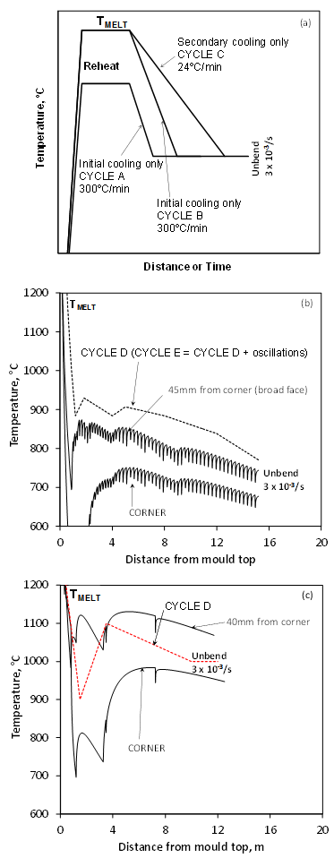 | Figure 2. Gleeble thermal cycles to simulate continuous casting: a) Average cooling cycles A,B,C, b) Cycles D, E for slabs - 600oC/min primary and 12oC/min secondary cooling rate and c) Cycle D for 140mm2 billets - 600oC/min primary and 24oC/min secondary cooling rate |
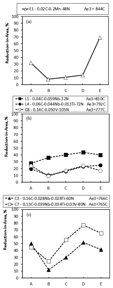 | Figure 3. Influence of thermal cycle on RA at 800ºC. a) low C-low Mn, b) low C-Nb-, V- and low Ti-Nb steels, c) peritectic Nb-Ti steels. The experimental error on %RA was ±10% |
The inclusion of thermal oscillations to simulate slab-roll contact improves accuracy but is only recommended for steels with a high Ae3. The effect of slab-roll contact was confirmed in figure 4, where SEM showed smooth ferrite growth planes on the austenite grain boundaries, which have only been observed when the ferrite films are thin. They were present at the surface of steel E1 after cycle D but absent after cycle E when large amounts of ferrite had formed. Cycle C had little effect on ductility suggesting little influence of cooling rate on this grade.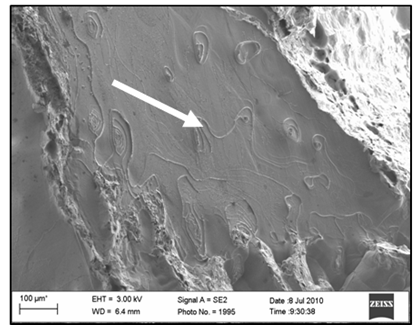 | Figure 4. Fracture surface showing smooth ferrite growth planes normally only observed when thin films are present. Cycle D in low C- low Mn steel El. Tested at 800ºC |
Figure 3b showed little variation in RA for any cycle applied to steels L1, L4 and C8 given an average error of about 10% typically found in RA tests. It appears that when the test temperature is marginally lower than the Ae3, then all thermal cycles produce similar ductility, implying that when the unbending temperature is close to the Ae3, then any of these ductility tests are fair predictors of poor ductility.Figure 3c showed that, in peritectic C-Nb-Ti steels C3 and C7, cycle A produced relatively high RA values at 800ºC, whilst cycles B and C deteriorated ductility only to recover dramatically in cycles D and E. The good ductility after cycle A was attributed to the limited dissolution of Ti and N at typical reheat temperatures. Stable TiN restricted the austenite grain size and limited fresh precipitation of fine TiN, which resulted in good ductility[10]. However, this cycle does not occur in practice. The excellent ductility found after quasi-industrial cycles D and E was due to coarsening of fresh precipitates during slow secondary cooling compared to the poor ductility in cycle B and average ductility in cycle C which indicated a strong dependence of these steels on secondary cooling rate.i) Low C–Nb-Ti slabs: Hot ductility curves after cycles B and D are shown in figure 5 for low C-Nb and low C-Nb-Ti steels.Figure 5a shows that, although cycle D significantly improved ductility in Nb steel L3, the RA was about 20% at 800oC and hence, crack susceptible. There was almost no change to RA in Nb steel L2, probably due to the low N content. With a minimum RA of 30% after cycle D, transverse cracking is thus not expected to occur in this grade.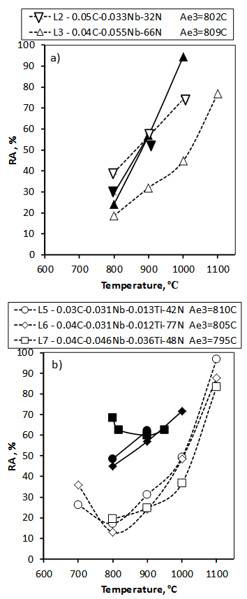 | Figure 5. Hot ductility curves for a) low C-Mn-Nb and b) low C-Mn-Nb-Ti steels. Dashed and open symbols: Cycle B , Solid and closed symbols: Cycle D, cf. figure 2b |
Figure 5b showed that cycle D significantly improved ductility compared to cycle B. For cycle B, Ti content resulted in a slight loss in ductility, whilst in cycle D, Ti level improved RA, especially in the lower austenite region – the RA between 800 and 900℃ was above 40% - sufficient to avoid cracking. This cycle explains the benefit of Ti additions to hot ductility of steels under industrial conditions and stresses the importance of accurate simulation of the surface and corner temperatures. The positive effect of Ti was more substantial at a higher Ti:N ratio of 7.5:1, even in high Nb steels L3 and L7 - The RA increased from 24% to 60% at 800℃.The variation in Nb level in figure 5b did not appear to affect ductility possibly because in melting, some Nb may precipitate as coarse, harmless eutectic[14].ii) Peritectic microalloyed slabs: Figure 6 shows hot ductility curves for peritectic Nb-microalloyed steels with and without Ti. Although the low Ti:N ratio improved hot ductility in steel C4, it was not as effective as the hyper-stoichiometric Ti:N ratio in steels C5 and C6, which contained sufficient Ti to combine with all the N. However, the ductility at 750oC was still low in all the steels. The ductility trough in C5 and C6 occurred below the Ae3 (766ºC) but started to recover again at 700ºC.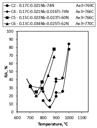 | Figure 6. Hot ductility of peritectic C-Nb and peritectic C-Nb-Ti steels - Cycle D, figure 2b |
The N level in these steels is important and small changes (0.001%) can have a large influence on hot ductility[4]. The slow secondary cooling rate of 12℃/min allowed the Ti-Nb rich precipitates to coarsen sufficiently so that they had less influence on the hot ductility in hyper-stoichiometric steels C5 and C6[3]. Generally, when the average precipitate size is larger than 20nm, as was found in these steels[6], only a small deterioration in hot ductility occurred. Higher Ti:N ratios improve the hot ductility and have been found to apply to steels with up to 0.007%N. N contents above 0.008% lead to unacceptably large precipitate volume fractions of TiN which, even if coarse, can be detrimental to ductility. A high volume fraction of fine precipitates increases the matrix strength, leading to enhanced grain boundary sliding[6]. Thus, if high N levels in peritectic steels are unavoidable, then Ti contents should be limited to about 0.015%.Nb-Ti-V microalloyed steel C7 gave substantially better ductility than C-V steel C8 which, in turn, was superior to C-Nb microalloyed grade C1, figure 7. Steel C7 was also superior to the Nb-Ti steels in figure 6 at 800-850℃ but RA decreased to a minimum of 28% below the Ae3 of 765ºC.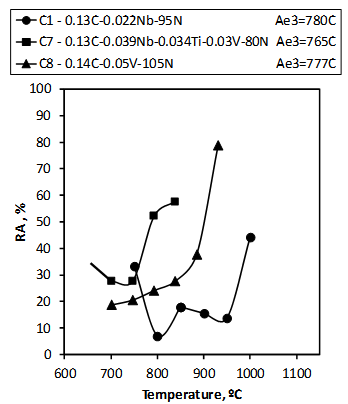 | Figure 7. Hot ductility of high N peritectic microalloyed steels. cf. Cycle D, figure 2b |
Figure 8a shows fine carbonitride precipitation in Nb-Ti steel C6 tested at 800℃, which explains the poor ductility – 30% - found at this temperature. Figure 8b shows a typical coarse, isolated carbonitride in Nb-V-Ti steel C7 at test temperature of 800℃, which is consistent with the relatively high RA of 50%, figure 7.Previous work[15] showed that, using a constant cooling rate from the melt (cycle B type test), Nb-V combinations result in better ductility than either Nb-only or V-only steels. Vanadium, when added either by itself or with Nb, forms a coarser, less detrimental precipitate and retards precipitation during unbending[16,17].The risk of industrial transverse corner cracking in steel C6 is illustrated in figure 9 by comparing the predicted temperature profiles of two slab casters via thermal modelling.The relatively soft cool at Caster I (7.5m radius) resulted in corner and off-corner temperatures during unbending to approach the Ae3 and produced frequent transverse cracks. The harder cooling at caster II (10m radius) forced the corner region temperatures below Ae3 during unbending and produced crack-free slabs, presumably due to the formation of sufficient ferrite at this stage of casting. This was confirmed by the recovery in ductility below 750ºC to above 30%, figure 6, the RA value below which transverse cracking in slabs is thought to occur. Similar behaviour was found for all the peritectic steels studied, which all had Ae3 temperatures in the 765-780ºC range. Thus, the interaction between steel chemistry and cooling patterns needs to be carefully characterized to avoid transverse cracking.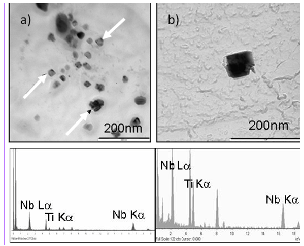 | Figure 8. TEM micrographs showing a)Nb-Ti microalloyed steel C6 with copious, fine NbTi(C,N) precipitation and b) a coarse NbTi(C,N) particle in Nb-V-Ti microalloyed steel C7. Tested at 800ºC |
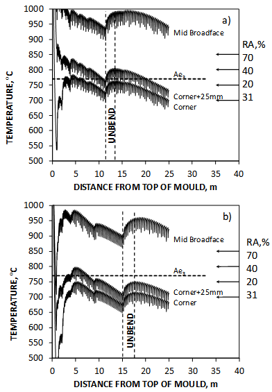 | Figure 9. Thermal profiles for steel C6 slabs (240mm x 900mm, speed = 1m/min) for a) caster I - softer cool, early unbending and frequent cracking and b) caster II - harder cool, late unbending with no observed cracking |
iii) Medium C billets: Cycle D was used to study a cracking problem in medium C microalloyed billets containing high N (≥0.008%). Figure 1b showed that the corner region in 140mm2 square billets is in the 900-1000oC range during the unbending operation for a withdrawal speed of 2,2mm/min, significantly higher than those found in 240mm thick slabs. Hot ductility curves for 0.35%C-V steels with and without Ti are shown in figure 10. The loss in hot ductility generally occurred at higher temperatures than those found for the low or peritectic C steels and well above their Ae3 temperatures. The high temperature ductility troughs in the medium C steels is thought to be due to grain boundary sliding[18] in coarse-grained austenite and smaller critical strains at higher C levels[19], rather than ductility loss due to strain-induced ferrite films found in low C and peritectic micro-alloyed grades.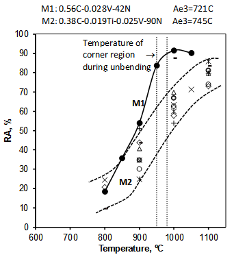 | Figure 10. Hot ductility curves for medium C-V-steel M1 and C-V-Ti steel M2 (eight steels). Cycle D, figure 2c |
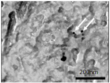 | Figure 11. TEM micrograph showing sparse, relatively coarse precipitation in V-only grade M1. Tested at 900℃ |
V-only steel M1 resulted in good ductility at above 900℃, due to the suppression of precipitation, figure 11. However, only when the temperature in the corner region drops to below 900℃, figure 1b, in steel M1 does the RA fall to dangerously low levels. The addition of Ti to medium C-V-N steel M2, although beneficial at low N levels, impairs hot ductility due to a higher precipitate volume fraction at higher N levels. Evidence to support this is the billet rejection histogram in figure 12 reported by Alvarez de Toledo et al[20].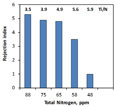 | Figure 12. Influence of total N content on rejection rate in medium C-Ti steels[20] |
Ti-high B steels M3-M5 had the poorest hot ductility in medium C steels containing high N and consequently the greatest risk for transverse cracking since RA fell to below 20% at the temperature expected in the corner region during unbending, figure 13. In steel M6, the lower total B content and near stoichiometric Ti:N ratio increased the solute B content to significantly improve ductility in the unbending temperature region and is expected to reduce transverse cracking in this steel type, especially when high N contents are unavoidable.Boron is beneficial to hot ductility provided the cooling rate is restricted to below 100oC/min[7]. Solute B improves hot ductility because of the segregation of B atoms to grain boundaries, where vacancies are occupied and the formation and propagation of microcracks is prevented[21]. Fast cooling rates allow fine BN precipitation to occur in the matrix. The small interparticle spacing would allow cracks to link up easily, promoting cracking due to microvoid coalescence[22]. The Ti content was too low to precipitate all N as TiN in steels M3-M5 and precipitation of BN and AlN was expected. A high rejection rate was experienced in these grades in the form of transverse cracks in billets and seams in rolled bars.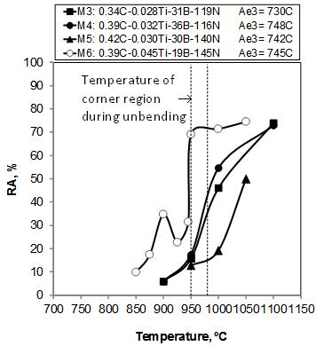 | Figure 13. Hot ductility curves for medium C-Ti-B steels M3-M6. Cycle D, figure 2c |
 | Figure 14. SEM micrographs of fracture surfaces of Ti-B steels tested at 950ºC: a) M5- fracture along austenite grain boundaries and b) M6 - high temperature ductile rupture |
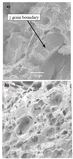
The fracture surfaces for steels M5 and M6 are shown in figure 14 after testing at 950℃. Steel M5, with low RA, fractured predominantly along the weak grain boundaries probably due to a low solute B content. Steel M6 had a high RA and experienced mostly high temperature ductile rupture. Thus, the higher solute B in steel M6 was expected to strengthen grain boundaries and improve ductility.
4. Conclusions
1. Simple reheating, followed by a constant cooling rate, can be used to assess transverse corner cracking in C-Mn steels containing combinations of Al, V and Nb. However, for improved simulation of transverse crack susceptibility of Ti-microalloyed steels, melted specimens, combined with rapid primary cooling and slow secondary cooling, should be used.2. In low C-Nb-Ti steels, the positive effect of Ti additions on reduction-in-area was shown to hold up to a Ti:N ratio of at least 7.5:1.3. In peritectic microalloyed steel slabs,a) containing Nb-(Ti), the Ti:N ratio should be stoichiometric and in high N steels, the Ti content should be limited to about 0.015% for acceptable ductility.b) containing V-Nb-Ti, the ductility is higher at 800℃ than in V-N, Nb-N and Nb-Ti steels due to a delay in sparse, fine precipitation.4. In medium C Ti-B billets with high N, good ductility can be achieved by limiting the total B content to about 20ppm and ensuring a near stoichiometric Ti:N ratio.5. When the unbending temperature of the corner region is near the Ae3, the risk of transverse cracking increases. For slab casting, the critical hot ductility for the avoidance of transverse corner cracking is estimated to be about 30%.
ACKNOWLEDGEMENTS
Thanks go to ArcelorMittal (SA) for permission to publish this work.
References
| [1] | K.M.Banks, A.S.Tuling and B.Mintz, Mat. Sci. and Tech, Vol. 28, 2012, pp.536-542. |
| [2] | K.M.Banks, A.S. Tuling, C. Klinkenberg, B.Mintz, Mat. Sci. and Tech, Vol. 27,2011, pp537-545. |
| [3] | K.M. Banks, A.S. Tuling and B. Mintz, Mat. Sci. and Tech. Vol. 27, 2011, pp1309-1314. |
| [4] | K.M. Banks, A.S. Tuling and B. Mintz, J. of South African Mining and Metallurgy, Vol.111, 2011, pp. 711-716. |
| [5] | K.M.Banks, A.S. Tuling and B.Mintz, Mat. Sci and Tech., 2012. In print. |
| [6] | B. Mintz, S.Yue and J.J. Jonas, Int.Mat. Reviews, Vol.36, 1991, pp. 187-217. |
| [7] | B. Mintz and D.N. Crowther, Int. Mat. Reviews, Vol.55, 2010, pp168-196. |
| [8] | K.M. Banks. 2013. To be published. |
| [9] | K.W. Andrews. J. Iron Steel Inst., 1965,Vol.203, 721. |
| [10] | B.Mintz and D.N.Crowther, Titanium Technology in Microalloyed Steel ed. T.N.Baker. Inst. of Materials, London (1997) pp98-114. |
| [11] | R. Abushosha, O. Comineli and B.Mintz. Mat. Sci. and Tech., Vol. 15, 1999, pp278-286. |
| [12] | O. Comineli, R. Abushosha and B.Mintz, Mat.Sci. and Tech, Vol.15, 1999, 1058-1067 |
| [13] | B.Mintz and A.Cowley, Mat.Sci. and Tech. Vol.22, 2006, 279-292. |
| [14] | R.Abushosha, R.Vipond and B.Mintz, Mat.Sci. and Tech., Vol.7, 1991, pp1101-1107. |
| [15] | K. Banks, A. Koursaris, F.Verdoorn and A.Tuling, Mat.Sci.and Tech., Vol.17, 2001, pp1596-1604. |
| [16] | B. Mintz and R. Abushosha. Ironmaking and Steelmaking, 1993, 20, 445-452. |
| [17] | M.G. Akben, B. Bacroix and J.J. Jonas, Acta Metall., Vol.31, 1983, pp161-174. |
| [18] | B.Mintz, Mat. Sci. and Tech, Vol.24. No.1, 2008, pp112-120. |
| [19] | T.Matsumiya, M.Ito, H.Kajioka, S. Yamaguchi and K. Nakamura. Trans. ISIJ, Vol.26, 1986, p540. |
| [20] | G. Alvarez de Toledo, A. Arteega and J.J. Laraudogeitia, Mater. Sci. Forum, 2005, pp500-501 |
| [21] | N.E. Hannerz, Trans. ISIJ, Vol. 25, 1985, pp149-158. |
| [22] | K. Cho, D.J. Mun, J.Y. Kim, J.K. Park, J.S Lee and Y.M Koo, Met. And Mat. Trans. A, Vol. 14A, June, 2010, pp1421-1428. |
 Abstract
 Reference
 Full-Text PDF
 Full-text HTML