-
Paper Information
- Next Paper
- Previous Paper
- Paper Submission
-
Journal Information
- About This Journal
- Editorial Board
- Current Issue
- Archive
- Author Guidelines
- Contact Us
International Journal of Metallurgical Engineering
p-ISSN: 2167-700X e-ISSN: 2167-7018
2013; 2(2): 161-178
doi:10.5923/j.ijmee.20130202.08
Structure-Property Correlation in TRIP Aided Steels
 Abstract
 Reference
 Full-Text PDF
 Full-text HTML
Shiv Brat Singh1, Tanmay Bhattacharyya1, 2, Ravi Ranjan1, Sandip Bhattacharyya2, Debashish Bhattacharjee2
1Department of Metallurgical and Materials Engineering, IIT Kharagpur
2R&D and SS, Tata Steel Limited
Correspondence to: Shiv Brat Singh, Department of Metallurgical and Materials Engineering, IIT Kharagpur.
| Email: |  |
Copyright © 2012 Scientific & Academic Publishing. All Rights Reserved.
The need for light-weight auto bodies with improved crash resistance and other safety parameters has encouraged the development of a new family of multi-phase steels having higher strength and better formability. High strength TRIP aided steel is the ideal material for such applications, but developing a grade that has good formability, coatability and weldability is a major challenge. The present work has been undertaken to address the issues of coatability and weldability as well as to target a high strength - ductility balance. The work includes Thermo Calc calculations to study the phase relationships, thermo-mechanical simulation, prediction of microstructure through artificial neural network and laboratory experiments in hot-dip galvanising simulator. Routine characterisation was done for the assessment of microstructure and properties. Three experimental steels were prepared in a vacuum induction furnace. The as-cast ingots were forged and then hot and cold rolled. Laboratory salt bath heat treatment of the cold rolled samples was carried out following the standard two-step heat treatment cycle consisting of intercritical annealing and isothermal bainitic transformation to obtain the desired microstructure and target mechanical properties. As a part of weldability assessment, the heat treated samples were spot welded. A difficulty with TRIP steels is their poor wettability during galvanising due to the formation of oxides of silicon on the surface. Two of these three test grades had aluminium as the replacement for silicon to improve wettability. Dew point during thermal processing plays a critical role and affects the wettability. The two-step heat treatment described above followed by hot dip galvanising was simulated with varying dew points in hot dip galvanising (Rhesca) simulator to assess the coatability of the samples. Very good strength-elongation balance was obtained for all the three steels and the samples with lower silicon and higher dew point showed better wettability and coatability. Weldability studies revealed that the introduction of post weld tempering cycles improves the weld nugget geometry, breaking load and failure mode under tensile shear loading. Tensile studies at high strain rate revealed a satisfactory performance of the steel even at 100 s-1 suggesting the fitness to be used at the crash prone zones of automotives.
Keywords: trip (Transformation Induced Plasticity), Wettability, Weldability, Crash Resistance Crumpling
Cite this paper: Shiv Brat Singh, Tanmay Bhattacharyya, Ravi Ranjan, Sandip Bhattacharyya, Debashish Bhattacharjee, Structure-Property Correlation in TRIP Aided Steels, International Journal of Metallurgical Engineering, Vol. 2 No. 2, 2013, pp. 161-178. doi: 10.5923/j.ijmee.20130202.08.
Article Outline
1. Introduction
- The need for addressing stringent environment and safety norms has compelled the automakers to design light-weight auto bodies with enhanced crash resistance. A new family of multi-phase steels having higher strength and better formability, named Transformation induced plasticity (TRIP) aided steel is gaining popularity to satisfy the demand as it has been adjudged as the most promising solution for the production of cars with low body mass because of the combination of high strength and large uniform elongation that they offer. The TRIP effect arises from deformation induced transformation of retained austenite to martensite[1]. It is accompanied by an invariant plane strain shape deformation as well as a volume expansion. This results in a higher strain hardening rate that delays the onset of necking, eventually resulting into higher uniform and total elongation [2]. An important feature of steels of this genre is enhanced ductility at a very high strength level[3]. TRIP effect enhances the mechanical properties by two mechanisms[4, 5]: (i) composite strengthening via the formation of hard martensite particles dispersed in the ferrite matrix and (ii) formation of dislocations around newly formed martensite regions as a result of the volumetric expansion during the austenite to martensite transformation.This steel is ideal for passive safety structural applications like bumper reinforcement, door impact beam etc., due to its high strain hardening rate and dynamic energy absorption capacity[6]. The microstructure of conventional TRIP aided steels comprises ferritic matrix (~55-65%) along with bainite (~25-35%) and metastable retained austenite (~5-20%)[7]. The TRIP effect depends on the amount of retained austenite and its stability to deformation induced transformation. Conventionally, TRIP aided steels contain about 1.5 wt% silicon which enhances the volume fraction and stability of the retained austenite by suppressing cementite formation during the isothermal bainitic transformation[8]. The solubility of Si in cementite is very small and therefore formation of a cementite nucleus in the presence of Si requires the diffusion controlled ejection of Si at the transformation front, causing a build up in the concentration of Si around the cementite nucleus. This locally increases the activity of carbon resulting in lowering of the flux of carbon and hence inhibits the development of cementite embryos[9]. Inhibition of carbide formation allows austenite to inherit a large amount of carbon, which lowers the Ms (martensite start) temperature and thus a considerable amount of metastable austenite is retained at room temperature[10].Conventional TRIP aided steel with high silicon (1.5 wt%) suffers from poor wettability during galvanising due to deleterious effect of silicon. It is reported that silicon in concentration higher than 0.5 wt% is detrimental to coatability[11]. High Si leads to poor weldability as well[12]. To avoid these problems silicon can be partially replaced by aluminium[13, 14, 15]. Aluminum, like silicon, is insoluble in cementite and helps in retarding cementite formation. Al facilitates coatability by forming an inhibition layer on the steel surface, which in turn prevents the formation of Si/Mn oxides and bare spots. However, aluminum is a weak solid solution strengthening element; complete replacement of silicon by aluminium is not suggested as these Al-containing steels cannot reach the strength level possible with Si alloyed steel[1]. Moreover, Chen et al.[16] have shown that Si level should be more than 0.8 wt% to obtain reasonable amount of retained austenite. Of late, addition of microalloying elements for enhancing the strength level has become very popular[17]. Niobium is considered to be very effective amongst these, especially for the steels where silicon is replaced either partially or fully by aluminum[17]. The effect of Nb addition is rather complex. It helps refine austenite formed during the intercritical annealing[18 ] which can lead to formation of some pro-eutectoid ferrite during cooling to the isothermal bainite transformation temperature and consequent carbon enrichment of the untransformed austenite. The finer grain size increases the stability of austenite by reduction of Ms (martensite start) temperature [18]. Niobium in solid solution retards recrystallisation of austenite, and the kinetics of austenite to ferrite transformation[17]. It also inhibits recrystallisation by strain induced precipitation. Furthermore, it increases the relative amount of retained austenite by approximately 25%, which can significantly improve the mechanical properties of the steel[19, 20]. Niobium accelerates the bainite reaction, particularly at the temperature of galvannealing[21]. As a result of increased bainite formation at a faster rate, it is possible to enrich the remaining austenite with carbon and stabilize it. It is thus possible to retain austenite in the final microstructure, even at the relatively low times of holding during galvannealing in a continuous line[21]. Therefore, microalloying, especially with niobium, attracts research studies in the area of development of new generation TRIP aided steels.P added TRIP-assisted steel[1] imparts solid solution strengthening and increases the stability of retained austenite. Oxides of phosphorous segregates at
 -Fe grain boundary resulting in reduction of boundary-flux and the extent of oxide formation on surface[22]. It also decreases the inter-diffusion of Fe and Zn, favours G1 formation and hinders
  It is more amenable to wetting by molten zinc. It is reported that P is not harmful from the point of view of embrittlement and as well as spot weldability up to 0.1 wt% for such steel compositions[23].Apart from alloy engineering, process optimization is also considered to be an important means for improvement of coatability. It is reported that if the hot dipping is done after a combination of intercritical annealing and isothermal bainitic transformation in a furnace atmosphere with a high dew point, the wettability improves significantly for conventional 1.5 wt% Si TRIP-aided steel. However, still some bare spots are unavoidable for CMnSi TRIP steel. On the contrary, the Si free CMnAl TRIP steel has a much better wettability when annealed at a low dew point. Therefore, dew point plays a crucial role for the surface quality of the steel and the wetting phenomenon in zinc bath during hot dip galvanizing[24].Integration of automotive structures made up of high strength/ advanced high strength steels are predominantly carried out through resistance spot welding (RSW) process due to consistency in quality as well as high productivity. But there is a large gap area to specify optimal welding conditions for TRIP-aided steels having relatively richer alloying additions, such as high Si, always deteriorate weldability[25, 26]. Better coatability during galvanizing of TRIP-aided steel necessitates major alloy engineering. It has invited renewed challenge for welding of TRIP-aided steel[27]. The weldability of ‘low carbon low alloyed’ TRIP-aided steel faces severe complexities. After solidification, welds become very hard and can show a brittle behavior. The hardness of the heat affected zone (HAZ) attains to the tune of 500 HV and more[28], and cold cracking phenomenon is very prone to occur. During resistance spot welding, especially, the interface between the plates can act like a notch and promotes fracture of the weld. It becomes very severe during coach peeling/ shear tensile fracture which usually produces partially interfacial fracture (inferior in terms of ductility) as opposed to full button peel off/ plug type (superior)[29]. The high strain rate properties of steel indicates the performance of the same under crash condition. It is already established that TRIP-aided steels are used in the crumpling zone of a car because of their high strain rate performance and ability of large dynamic energy absorption. Therefore, dynamic testing is of special interest for the steel grades under discussion. Yield stress and ultimate tensile strength of TRIP aided steel increase continuously as it occurs for ferritic steels, but showing a smaller slope. At very high strain rate the elongation values of these steels are as high as under quasistatic testing conditions or even higher. This behavior is probably correlated to adiabatic heating. The used test set up and specimen size can lead to a local temperature increase up to 120 K. TRIP steel shows very good energy absorption quality even if at 200 s-1 strain rate[30]. Both temperature and strain rate affect the retained austenite transformation. At high strain rates, the uniform elongation decreases, whereas the total elongation and energy absorption increase. With raising test temperature, the tensile strength is reduced and the mechanical properties generally deteriorate, especially at 110°C. However, excellent mechanical properties are obtained at 50°C and 75°C [31].High strain rate properties being the indicator of performance under crash condition, a detailed study on tensile behaviour under dynamic loading has been presented for a simulated performance under crash condition with an overview on the study of wettability (coating performance during hot dip galvanising) and weldability.
2. Selection of Materials and Processing Parameters
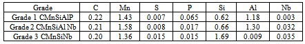
- Three steels were selected for this work. The compositions are shown in Table 1.
|
|
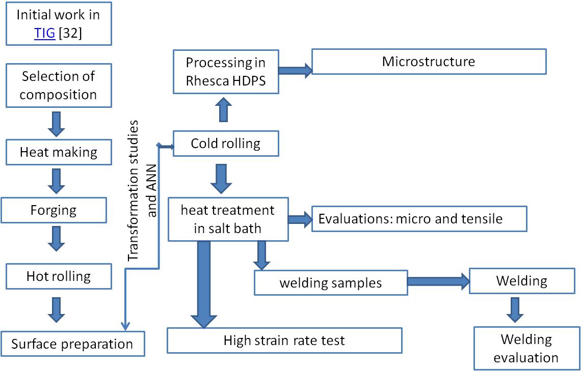 | Figure 1. Process flow |
|
3. Performance Appraisal of Wettability and Weldability Study
- Wettability (coating performance during hot dip galvanizing in Rhesca HDPS):An assessment[34] of the coating quality revealed that the steels with silicon level lower than that of conventional (1.5% silicon) TRIP-aided steel showed better wettability, coating thickness and adherence property. At higher dew point (+ 5℃) during, the coatablity was much improved than that at the lower dew point (- 40℃). The rationale for the same is as follows: for the steel grades where silicon is partially replaced by aluminium, some silicon and manganese would not be oxidised internally and hence some enrichment of these elements on the surface will occur during the annealing at a low dew point. Therefore better coating occurs at higher dew point. WeldabilityWeldability studies were carried out with samples heat treated in salt bath furnaces. Literature review[30-31] and a number of trials suggested that introduction of a post welding heating cycle could improve the weldability in terms of nugget diameter. Accordingly, a post welding heating was introduced in the final trial. The welded samples were subjected to tensile load in Instron 8801with a cross head speed of 1mm/minute. The test results revealed significant improvement in terms of nugget formation and geometry, failure mode (exhibiting achievement of expected plug type mode of failure) and load of weld at failure[35].No major disparity was apparent for the three different grades for the weld zone and the HAZ. However, superior properties were observed for grade 1 and grade 2 to that of grade 3.
4. Assessment of Structure Property Correlation Under High Strain Rate Testing
- For high strain rate testing, another set of samples, cold rolled samples, cut in to required size (Fig. 2), for all three grades were heat treated as per above cycles in two adjacent salt bath furnaces for intercritical annealing and isothermal bainitic transformation (allowing shortest possible manual-shifting time from IA to IBT bath) followed by oil quenching to the room temperature. For high strain rate testing, the surfaces of the heat treated samples were made free from loose scales by grinding of emery papers and cleaned with acetone.
4.1. Characterisation
- All tests for the high strain rate work were accomplished on a servo hydraulic Zwick/ Roell Rel 1852 high-speed tensile testing[locate at IEHK, RWTH University, Aachen] machine including a digital measuring and controlling unit. The Vmax and Fmax for the machine are 10 m/s and 12 kN (to be reconfirmed) respectively. The tests had been carried out at strain rates 1 and 100 s-1 (average). Each test had been done for three times for Grade 1 and 2, and twice for Grade 3 due to paucity of material. German specification for dynamic tensile test[36], was followed for this work. The test pieces were made in accordance with the dimensions specified in The strain rate was determined based on the available condition of the equipment. However, published experimental data and internal circulations of leading steel manufacturers[37] are in agreement with the maximum strain rate (100 s-1) of the range selected here, to have resemblance with the crashing condition of passenger car components. For quasistatic test with a strain rate of 3.33 x 10⁻⁴ s-1, data has been captured from Table 3.The force measurement during the test was done using a piezoelectric load cell instrumented with a Weg Zimmer (opto-elektronisch) extensometer. The storage of test data was done with a 4-channel transient recorder (sampling rate 1 MHz, 10 bit analogue/ digital converter) and later for further calculation on a personal computer. To evaluate the results, the recorded data were first converted into technical stress strain diagrams allowing the determination of the mechanical properties by use of special software developed by IEHK, Aachen. At high strain rates the force signal was superimposed by oscillation, caused by the inertia of the test equipment, making the direct determination of the characteristics values impossible. Therefore a cubic spline was utilized to approximate the unfiltered stress-strain signal, allowing the gathering of the strength properties. Earlier works showed good conformity of results obtained in this way, using the load cell instrumented with strain gauges plus spline approximation, compared to the results achieved using the strain gauges fixed directly on the specimen[38].
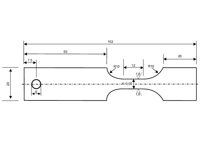 | Figure 2. Specified sample geometry for high strain rate testing. All dimensions are in mm. The thickness of all the samples varied between 1.2 to 1.4 mm |
4.2. Results and Discussion
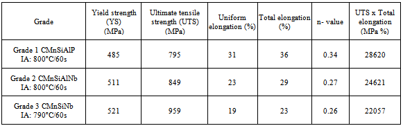
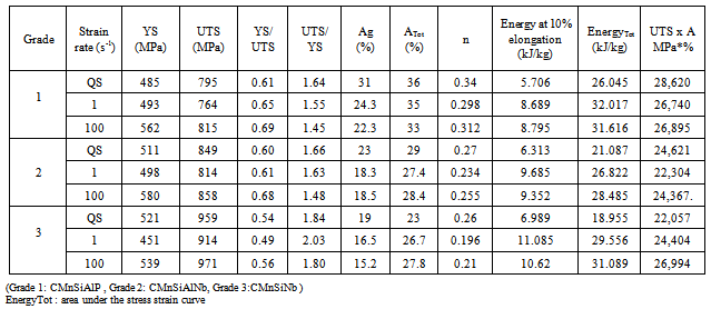
- The details of the test results for higher strain rate from dynamic tensile testing (1 and 100 s-1) vis-à-vis the quasistatic properties are tabulated below (Table 5):
|
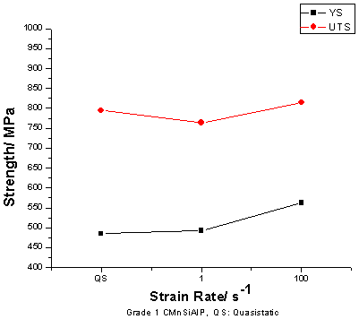 | Figure 3. Variation of strength with respect to strain rate_ Grade1 |
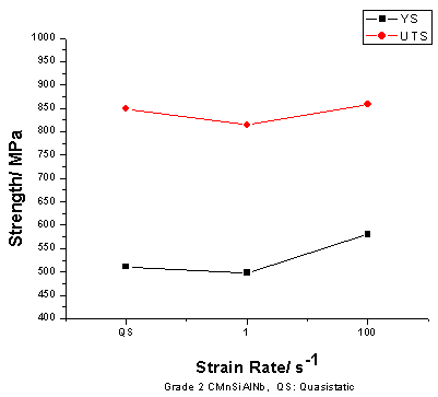 | Figure 4. Variation of strength with respect to strain rate_ Grade2 |
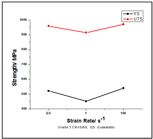 | Figure 5. Variation of strength with respect to strain rate_ Grade3 |
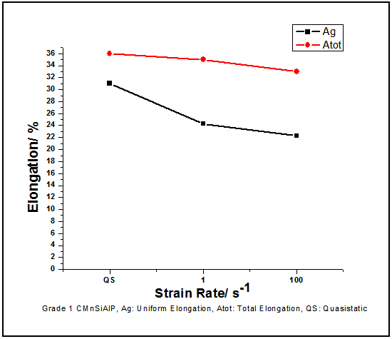 | Figure 6. Variation of elongation (total and uniform) with respect to strain rate_ Grade1 |
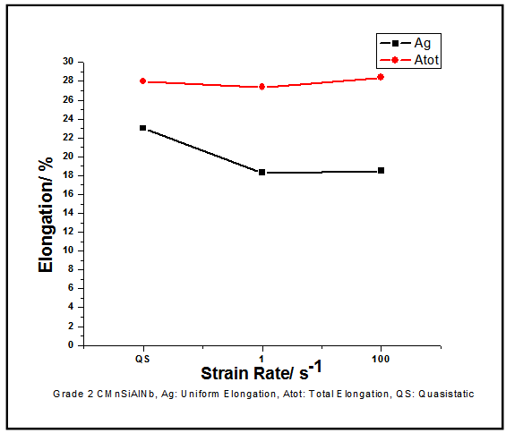 | Figure 7. Variation of elongation (total and uniform) with respect to strain rate_ Grade2 |
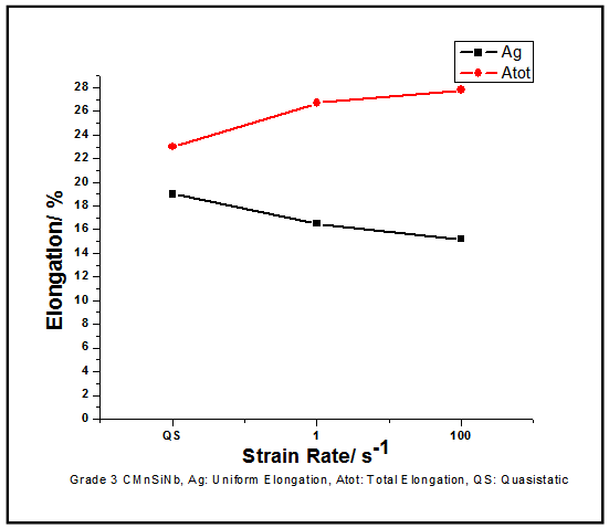 | Figure 8. Variation of elongation (total and uniform) with respect to strain rate_ Grade3 |
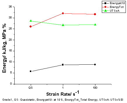 | Figure 9. Variation of energy with respect to strain rate_ Grade1 |
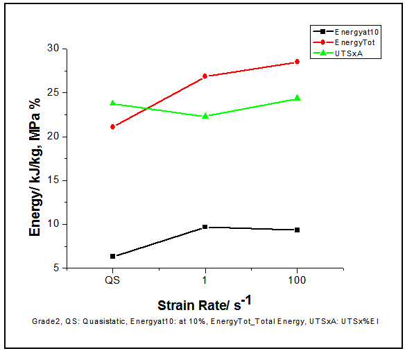 | Figure 10. Variation of energy with respect to strain rate_ Grade2 |
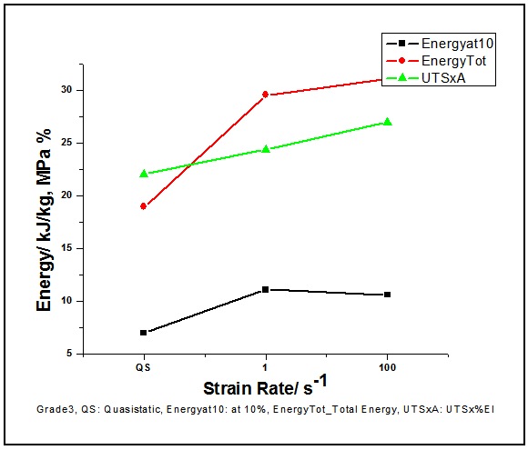 | Figure 11. Variation of energy with respect to strain rate_ Grade3 |
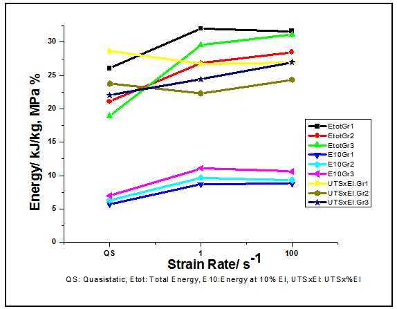 | Figure 12. Comparative diagram on energy variation with respect to strain rate |
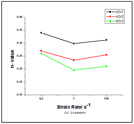 | Figure 13. Comparative diagram on variation of n-value with respect to strain rate |
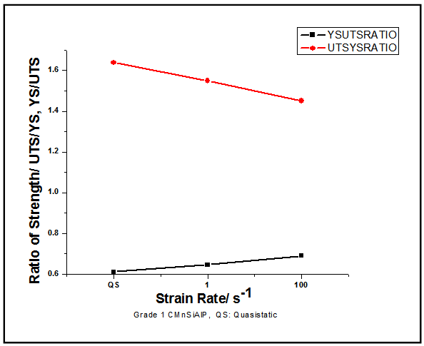 | Figure 14. Variation of strength ratio with respect to strain rate_ Grade1 |
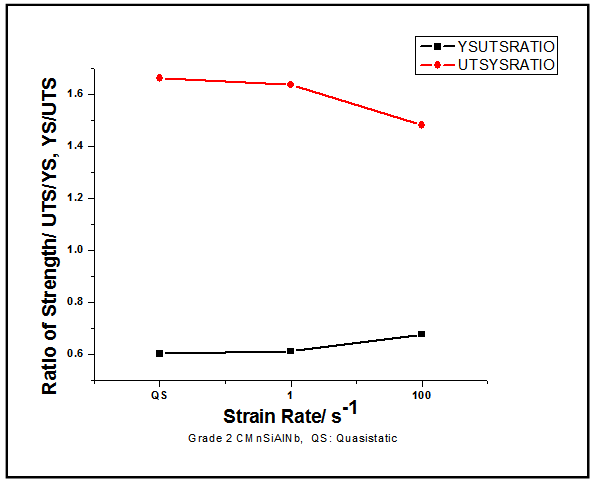 | Figure 15. Variation of strength ratio with respect to strain rate_ Grade2 |
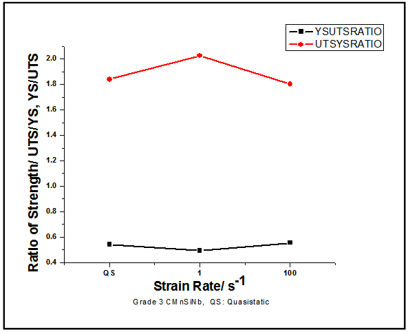 | Figure 16. Variation of strength ratio with respect to strain rate_ Grade3 |
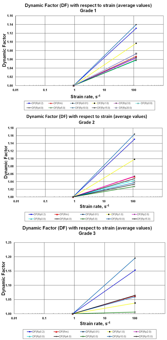 | Figure 17. Variation of Dynamic Factor against strain rate: a. Grade1, b. Grade 2, c. Grade 3 |
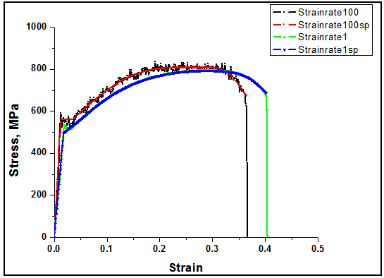 | Figure 18. Engineering stress strain diagram for strain rates 1 and 100 s-1 with and without spline (sp) for Grade 1_Specimen 1 |
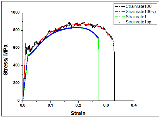 | Figure 19. Engineering stress strain diagram for strain rates 1 and 100 s-1 with and without spline (sp) for Grade 2_Specimen 1 |
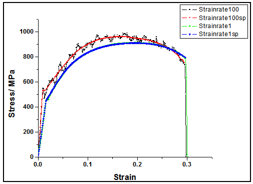 | Figure 20. Engineering stress strain diagram for strain rates 1 and 100 s-1 with and without spline (sp) for Grade 3_Specimen 1 |
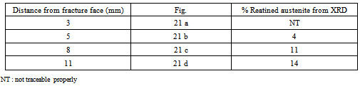
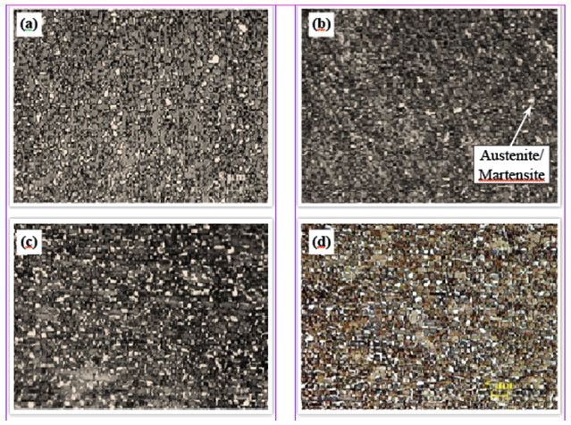 | Figure 21. a to d show microstructure for Grade 2 after tensile test at 100 s-1 From fracture face towards the grip. Microstructure: Ferrite + Bainite + Austenite/ Martensite (white phase) |
|
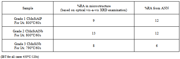
5. Conclusions
- Three low carbon TRIP-aided steels have been developed through cold rolling, two step heat treatment and galvanising route. The material under study has shown very good performance under quasistatic as well as high strain rate tensile test resulting in high ultimate tensile strength with high total and uniform elongation. The material also has a high strain hardening exponent which has direct correlation with the availability of retained austenite in the microstructure after heat treatment. The volume fraction of retained austenite measured through optical metallography had a reasonably good match with the value obtained through XRD technique. These values corroborated the amount of retained austenite predicted through artificial neural network model. Changing the dew points, the coatability have been improved and it has been observed that the samples with lower silicon and treated at higher dew point showed better coatability during hot dip galvansing coating.Trials for resistance spot welding have revealed that the steels are weldable. Introduction of post weld tempering cycles improves the weld nugget geometry, breaking load and failure mode under tensile shear loadingIt is observed form the results that in general at high strain rates, the uniform elongation had shown decrement, whereas the total elongation and energy absorption were increased (except some deviations). The observations has corroborated various other works[30].It is envisaged that during the high strain rate testing, temperature increases sharply which remains within the system. So this deformation mechanism is an adiabatic one which may play a significant role in restricting the extent of transformation of austenite to martensite[31], and thus, the reason behind the decrease in tensile strength during this adiabatic deformation can be explained due to the decrease of flow level and less transformation to martensite. The decrease in strength due to adiabatic deformation could also be due to the decrease in the flow level in accordance with the temperature dependence of yield point as well as due to decrease in strength decreases as exhibited in the temperature dependence of the strengthening graph[40].For 1 s-1, the impact of adiabatic heating being high, a trend of decrease in strength is very common. Whereas, for 100 s-1,as the testing time is extremely low, that might not have much impact over the transformation of austenite to martensite resulted in higher martensitic transformation except Grade 3. Microstructure of Grade 3 has revealed that it had relatively lower austenite and there could have been higher martensite as it had been evident from calculation of Ms temperature with the help of x-ray diffraction as well as calculation through Thermo-Calc.Energy absorption is a function of tensile strength[41]. The tensile strength having been linearly proportional to the volume fraction of martensite in the structure[42, 43], presence of martensite from higher transformation of austenite or due to preexisting higher martensite, the energy level becomes higher. This has been reflected for higher energy levels for Grade 2 at 100s-1, and for Grade 3, both at 1 and 100 s-1.It is also established from this work that the behaviour at higher strain rate of the three developed steels, especially in terms of energy, have made them qualified to be applied to manufacture crash resistant components over the conventional high strength steels[44].
ACKNOWLEDGEMENTS
- Authors are personally indebted to Prof. Wolfgang Bleck, Head, Department of Ferrous Metallurgy, IEHK, RWTH Aachen University for their support to carry out the work. Authors thankfully acknowledge Dr P K Banerjee, Chief (Actg.), R&D and Scientific Services, Tata Steel Ltd., Prof. S. Das, Head, Department of Metallurgical and Materials Engineering, IIT, Kharagpur, Authors are thankful to the Department of Science andTechnology and Ministry of Steel, Government of India, International Bureau of the Federal Ministry of Education and Research, Germany for their partial financial support for the work. Authors also thank Prof. Subhabrata Datta of School of Materials Science and Engineering, Bengal Engineering and Science University, Shibpur, Howrah, Dipl. Ing. Christoph Keul, RWTH Aachen University, Dr. Monideepa Mukherjee of Tata Steel Ltd. for their hearty support.
References
| [1] | B. C. De Cooman, Current Opinion in Solid State and Material Science 8 (2004) 285-303. |
| [2] | V.F. Zackay, E.R. Parker, D. Fahr and R. Busch, Transactions of the American Society for Metals 60 (1967) 252-259. |
| [3] | B. Mintz and J.C. Wright, J.Iron and Steel Institute 208 (1970) 401-405. |
| [4] | E.M. Bellhouse and J.R. McDermid, Metallurgical and Materials Transaction A, Volume 41A (June 2010) 1460-1473. |
| [5] | P. Jacques, Q. Furne´mont, A. Mertens, and F. Delannay: Philos. Mag. A, Vol. 81 (2001) 1789–1812. |
| [6] | J. H. Jung et al., 2008 International Conference on New Development in Advanced High Strength Steels, 25-37. |
| [7] | T. Heller and A. Nuss, Proceedings of the Intermational Symposium on Transformation and Deformation Mechanisms in Advanced High Strength Steels, eds. M. Militzer, W. J. Poole and E. Essadiqi, CIM, Montreal (2003) 7-20. |
| [8] | O. Matsumura, Y. Sakuma and H. Takechi, Transactions ISIJ 21 (1987) 570-579. |
| [9] | W. S. Owen, Transactions of the American Society for Metals, 46 (1954) 812-829. |
| [10] | E. Girault, P. Jacques, Ph. Harlet, K. Mols, J. Van Humbeeck, A. Aernoudt, and F. Delannay, Materials Characterization 40 (1998) 111-118. |
| [11] | B. Mintz, International Materials Review 46 (2001) 169-197. |
| [12] | ASM Handbook, Vol. 6, Welding, Brazing and Soldering, ISBN 0-87170-383-3 (Dec. 1993) 405-407. |
| [13] | J. Maki, J. Mahieu, B. C. De Cooman, and S. Claesseur, Materials Science and Technology, Vol. 19 (Jan. 2003) 125-131. |
| [14] | W. Bleck, A. Frehn, and J. Ohlert, Proceedings of the International Symposium on Niobium, Orlando (2001) 727-752. |
| [15] | J. Gao and M. Ichikawa, Proceedings of the International Conference on Advanced High Strength Sheet Steels for Automotive Applications, AIST, Winter Park, Colorado (2004) 107-116 |
| [16] | Chen et al., SE AISI Q (April 1991) 44-49. |
| [17] | D.Krizan, B. C De Cooman and J. Antonissen, Proceedings of the International Conference on Advanced High Strength Sheet Steels for Automotive Applications, AIST, Winter Park, Colorado (2004) 205-216. |
| [18] | K. Hulka, W. Bleck and K. Papamantellos, Proceedings of the 41st Mechanical Working and Steel Processing Conference, Iron and Steel Society, Baltimore (1999) 67-88 |
| [19] | X. Liu, P. Karjalainen, and J. Pertula, Thermo-mechanical Processing in Theory, Modelling and Practice” ed. W. Hutchinson et al., (1996), Stockholm, Sweden, 240-248 |
| [20] | M. Onink, Th. M. Hoogendoorn and J. Colijn, Material Science Forum, 284-286 (1998), 185-192. |
| [21] | Debanshu Bhattacharya, Proceedings of the International Conference on Microalloyed Steels: Emerging Technologies and Applications (2007), Ed. Debashish Bhattacharjee et al., 50-60. |
| [22] | H. K .D. H. Bhadeshia and R. W. K. Honeycombe, Steels Microstructure and Properties, Third Edition, 2006, Elsevier Ltd. |
| [23] | Liesbeth BARBÉ, Kim VERBEKEN and Emiel WETTINCK, ISIJ International, Vol. 46 (2006), No. 8, 1251–1257. |
| [24] | J. Mahieu, S. Claessens, B.C. De Cooman, Metallurgical and Materials Transaction A Volume 32A, November 2001, 2905-2908. |
| [25] | ASM Handbook, Vol. 6, Welding, Brazing and Soldering, ISBN 0-87170-383-3 (Dec. 1993) 405-407 |
| [26] | T. Herai et al, Resistance spot welding of high strength steel sheets, IIW Doc. III, 664-80 |
| [27] | M. I. Khan, M. L. Kuntz, E. Biro and Y. Zhou, Materials Transactions, Vol. 49, No. 7 (2008) pp. 1629-1637. |
| [28] | Cretteur Laurent et al., Steel Research, ISSN 0177-4832, 2002, vol. 73, pp 314-319. |
| [29] | Yun Peng et al., Materials Science Forum Vols. 638-642 (2010) pp 3591-3596. |
| [30] | Rong TIAN, Lin LI, BC De Cooman, Xi-chen WEI and Peng SUN, Journal of Iron and Steel Research, International,Volume 13, Issue 3, May 2006, Pages 51-56. |
| [31] | Wolfgang Bleck and Ingo Sacheal, Steel Research 71(2000) No. 5—32. |
| [32] | Tanmay Bhattacharyya, Shiv Brat Singh, Sourav Das, Arunansu Haldar, Debashish Bhattacharjee, Materials Science and Engineering A 528 (2011) 2394–2400. |
| [33] | Tanmay Bhattacharyya, Shiv Brat Singh, Swati Sikdar Dey, Sandip Bhattacharyya, Wolfgang Bleck, Debashish Bhattacharjee, Materials Science and Engineering A, MSEA D12 02974 (under publication). |
| [34] | Indian Patent Application No. 633/KOL/10 of 11 .06. 2010. |
| [35] | Indian Patent Application No.1356/KOL/2011 of 21. 10. 2011. |
| [36] | Standard for high strain rate test, “Stahl Eisen Prüfblatt SEP 1230”. |
| [37] | Internal Document, Corus |
| [38] | D. Stark-Seken, W. Bleck, W. Dahl, Materialprufung, 37 (1995) 165-168. |
| [39] | I. D. Choi, D. M. Bruce, S. J. Kim, C. G. Lee, S. H. Park, D. K. Matlock, J. G. Speer, ISIJ International, 42 (2002) 1483-1489. |
| [40] | W. Bleck, Text Book on Material Testing for RWTH Students, Aachen University. |
| [41] | R.G. Davies, Metall. Trans. A, 10 (1979) 1549–1555. |
| [42] | R.G. Davies, Metall. Trans. A, 9 (1978) 671-679. |
| [43] | J. F. Butler, J. H. Bucher, Seminar on Vanadium Cold Passing and Dual Phase Steel, 18-20, Oct. 1978, Berlin. |
| [44] | R. G. Davies, C. L. Magee, Proc. Symp. On Structure and Properties of Dual Phase Steel, February 19-21, 1979, New Orleans, The Metal. Soc. AIME. |