-
Paper Information
- Next Paper
- Previous Paper
- Paper Submission
-
Journal Information
- About This Journal
- Editorial Board
- Current Issue
- Archive
- Author Guidelines
- Contact Us
International Journal of Metallurgical Engineering
p-ISSN: 2167-700X e-ISSN: 2167-7018
2013; 2(1): 100-110
doi:10.5923/j.ijmee.20130201.15
Role of Base Metal Microstructure on Tensile Properties and Weldability of Simulated Continuously Annealed Advanced High Strength Steels
 Abstract
 Reference
 Full-Text PDF
 Full-text HTML
Kumkum Banerjee
R&D Dept, Tata Steel Limited, Jamshedpur, India
Correspondence to: Kumkum Banerjee, R&D Dept, Tata Steel Limited, Jamshedpur, India.
| Email: |  |
Copyright © 2012 Scientific & Academic Publishing. All Rights Reserved.
Advanced high strength steels (AHSS) are several families of steels (dual phase, transformation-induced plasticity, complex phase and martensitic steels) that constitute ferrite along with low temperature phases--martensite, bainite and/or retained austenite, in adequate quantities, to obtain desired mechanical properties. These steels find their applications in automobiles and are able to enhance mechanical properties with reduced weight that make them cost effective, fuel efficient and environment friendly. All AHSS are produced using proper chemistry design in association with controlled rate of cooling from the austenite–ferrite phase region, either on the run-out table in a hot rolling mill or in the cooling section of a continuous annealing line. This ensures high strength and other desired properties essentially through the low temperature phase transformation products. In the present investigation, the base metal microstructure had played a key role in dictating tensile properties and weldability of spot welded AHSS in simulated continuously annealed conditions. A few miocroalloyed AHSS with low carbon equivalent were produced in a laboratory air induction furnace and were subsequently hot forged and rolled in the laboratory. Continuous heating and cooling transformations were vividly studied in a Gleeble 1500D to determine intercritical temperature regimes and the transformation temperatures in association with cooling rates of the low temperature transformation products. The hot rolled samples after duly cold rolled were submitted to strip annealing simulation to mimic actual continuous annealing, employing a Gleeble 3500 thermomechanical simulator. Two types of annealing cycles were simulated to examine the effect of cooling rate and bainite alongside fine microalloying precipitates on tensile properties and weldability. The annealing cycles that resulted in ferrite, 37% bainite and martensite in association with nano-sized Mo-C were successful in delivering the satisfactory combination of tensile properties and weldability.
Keywords: Advanced High Strength Steel, Continuous Annealing, Microalloying Precipitates, Haz Softening, Tensile Strength, Ductility, Resistance Spot Welding, Weldability
Cite this paper: Kumkum Banerjee, Role of Base Metal Microstructure on Tensile Properties and Weldability of Simulated Continuously Annealed Advanced High Strength Steels, International Journal of Metallurgical Engineering, Vol. 2 No. 1, 2013, pp. 100-110. doi: 10.5923/j.ijmee.20130201.15.
Article Outline
1. Introduction
- In recent years, light-weight-fuel-efficient vehicles that ensure passenger safety have become a priority for automotive industries. Manufacturing of such vehicles has been possible by the development of high strength multiphase advanced high strength (AHSS) steels. AHSS is a term used to describe several families of steels (dual phase-DP, transformation induced plasticity—TRIP, complex phase–CP and martensitic steels) that contain ferrite, martensite, bainite and/or retained austenite in sufficient quantities to produce desired mechanical properties. Some types of AHSS have higher strain hardening capacity resulting in strength-ductility balance that is superior to conventional steels while other types possess ultrahigh yield and tensile strength in association with bake hardening behaviour[1]. All AHSS are produced by controlling the cooling rate from the austenite –ferrite phase, either on the run-out table of the hot rolling mill or in the cooling section of the continuous annealing line to ensure high strength levels through bainitic-martensitic transformation[2]. However, such transformations can not be achieved unless the cooling rate is over a critical threshold that depends on steel composition[3]. The critical cooling rate increases with decreasing alloying additions and as the cooling rates attainable by industries are limited, without the addition of alloying elements, achievement of high strength is not possible.Problems in welding AHSSGenerally, sheet steels can be hardened by the addition of C, Si, Mn, P etc. However, increasing alloying elements, such as C, Si and Mn enhances quenching hardenability of steels that affects weldability adversely[2-5]. Weldability of steels depends upon carbon equivalent (CE) that gives the measure of hardenability of the steel and is a function of alloying elements present.The following expression is widely used for expressing CE of AHSS[6].CE = C + Si/30 +Mn/20+2P+4S (mass%)Resistance spot welding is a favoured method for joining advanced high strength steels[7]. The welding lobes of AHSS are narrower than mild and high strength steels. Further, AHSS tend to exhibit higher expulsion, higher electrode wear and most importantly, they fail during pull button test resulting in interfacial failure. The acceptable strength is achievable in these spot welded steels with full button pull, partial button pull or partial interfacial fracture.Several researchers on AHSS have reported the welding related problems for the formation of matensite in the weld nugget[8, 9]. Martensite can also form in resistance spot welds, even at low carbon levels as cooling rate associated with spot welding[10, 11] is quite high. Similar observations were made while laser beam welding (LBW) was conducted on AHSS[12, 13]. The hardness achieved in the steels is directly associated with the fast cooling in the welding processes that can achieve cooling rate of the order of 103-105 ℃/s[5,14]. The hard martensite thus formed due to high cooling rate, provides a path for a crack to propagate. In addition, rapid cooling can cause porosities towards the edges of the weld where stress concentration is highest in a peel test[15] and also solidification cracking enhancing the chances of interfacial failure of a spot weld[14].Shrinkage, solidification cracks and liquid metal embrittlement in DP 600 were also observed by Milititsky et al[16] in some welds, where weld current and hold time were found responsible for the formation of such imperfections. In another work[17], the detection and prediction of expulsion during spot welding of DP600 were reported. Several researchers have reported about the interfacial failures in DP600 steel while the weld size exceeded the minimum threshold size[189]. In addition, Wang et al. also found interfacial fracture in DP600 steel weld buttons for the thicker gages[19-21]. Such failures were attributed to solidification cracks and shrinkage voids[22].It can be mentioned that HAZ softening may occur in the case of AHSS with significant amount of martensite[23, 24] in the base metal that can be attributed to martensite tempering at the points of the weld where the temperature approached A1 (subcritical HAZ). Further, as DP steel essentially derive its strength from the composite microstructure of ferrite and martensite and as martensite is a thermally unstable phase, it tends to decompose in the heat affected zone (HAZ) resulting in softening and thus causing hardness reduction. This phenomenon is termed as HAZ softening[25, 26]. HAZ softening is a very complex phenomenon that is affected by steel composition, base metal martensite content, prestrain and heat input[27-29] and it can have detrimental impact on weldment. HAZ softening was also reported by Dancette et al[30, 18] in DP980 due to martensite tempering, however, the presence of a low amount of martensite in the base metal of DP450, helped avoid HAZ softening.In this article, a detailed discussion on the role of base metal microstructure on tensile properties and weldability of the steels is presented.
2. Experimental
2.1. Material
- Two heats were made using a 25-kg in-house laboratory air induction furnace. Chemical composition (in wt%) of the heats (Heat Nos. 9 and 14) along with the carbon equivalents are presented in Table 1.
|
2.2. Hot Rolling
- Equilibrium transformation temperatures (Ae1 and Ae3) for the steels were calculated using Thermo-Calc (TCFE3) so that finish rolling temperatures remained 30-40℃ above the A3 temperatures. The ingots were forged at 1200℃ for 2 hrs. and subsequently hot rolled by soaking at 1200℃ for 1-hr in a furnace at RDCIS SAIL, Ranchi. The Ae3 temperature of the steels is 847-850℃, while the finish rolling temperatures (FRT) of the steels 9, 10 and 14 were 875, 862 and 885℃, respectively.
2.3. Dilatometry
- For designing continuous annealing cycles, AC1 and AC3 temperatures were determined by continuous heating and Bs/Ms temperatures through continuous cooling transformation (CHT & CCT) tests on Gleeble 1500D thermomechanical simulator using 80mm long-3mm-dia samples from hot rolled materials.For CHT, samples were heated at the rate of 1-100℃/s to 1050℃, followed by air cooling. While, for CCT, samples were heated to 1050℃ for 2-mins. at the rate of 5℃/s, followed by cooling at the rate of 0.5℃/s-100℃/s.For microstructural analysis of the CCT samples, all samples were cut in half, approximately at the position of the thermocouple and were prepared for metallographic examination following standard sample preparation technique, while using 2% nital to reveal microstructures.
2.4. Continuous Annealing Simulation
- The hot rolled samples were cold rolled to ~ 0.8-1 mm using the laboratory cold rolling set-up at NML Jamshedpur for subsequent continuous annealing (CAL) simulation. To simulate continuous annealing cycles, strip annealing facility of RDCIS, SAIL Ranchi was utilized. The strip samples of 260mmX50mm were used for the annealing simulation.The simulation was carried out in the intercritical temperature range (α+γ) that was determined by CHT tests on Gleeble 1500D. Two types of continuous annealing cycles were designed for strip annealing simulation on Gleeble 3500 to examine the effect of cooling rate and bainite on tensile properties and weldability.
2.5. Effect of Cooling Rate
- Cold rolled samples of Heat-14 were used to examine the effects of cooling rate in the simulated annealing cycles. The parameters used in the annealing cycles along with their thermal cycles are given in Table 2.
|
2.6. Effect of Bainite
- Cold rolled samples of Heat-9 were used to examine the effects bainite in the simulated annealing cycles. The parameters used in the annealing cycles along with their thermal cycles are given in Table 3.
|
2.7. Welding of Annealed Samples
- A DC MF-90 Spot Welder was used to spot weld the annealed samples using a Cu-Cr-Zr alloyed electrode of 5-mm truncated tip diameter. The squeeze force, weld current and weld time were 22daN, 5.8-6kN and 180-200s, respectively. After welding, the samples were submitted for peel-testing using a laboratory vice.
2.8. Microscopy, Hardness Measurements and Tensile Testing (Hot Bands, Annealed Samples and Welded Samples)
- Cross sections of samples after hot rolling, cold-rolled-annealing and welding were ground and polished following standard metallographic procedures. Thereafter, the samples were examined by optical (OM), high resolution scanning electron microscopy (FEG-SEM) and transmission electron microscopy (TEM) equipped with energy dispersive spectroscopes (EDS). For OM and FEG-SEM, the polished specimens were etched with 2% nital. For TEM, thin foils of 3-mm diameter were punched from mechanically thinned ~60 mm slices and were electro-polished in a solution of methanol and 10% perchloric acid at -40℃ using a twin-jet electropolisher. Thin foils were examined using a Phillips CM12 transmission electron microscope operated at 120kV.Microhardness measurements of various phases present in the hot bands and the CCT samples were conducted using LECO LM 247AT Vickers microhradness tester, while macro hardness for the hot bands and resistance spot weldments were measured using a LECO LV700AT Vickers Hardness tester.The annealed samples were further submitted to tensile testing following ASTME-08 sample dimension on Instron 5582 tensile tester to record the tensile data.
3. Results and Discussion
3.1. Hot Band Microstructure
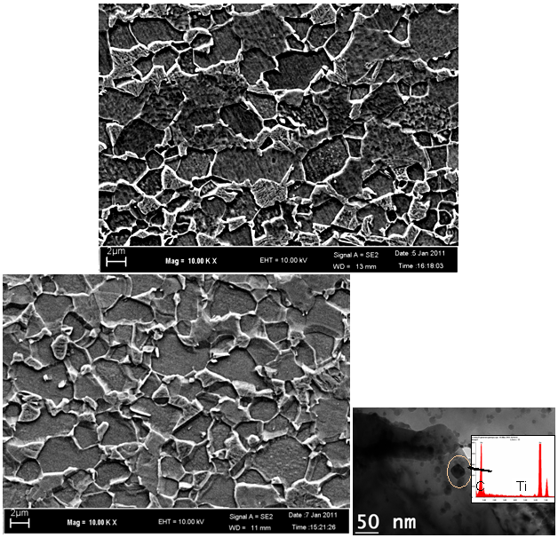
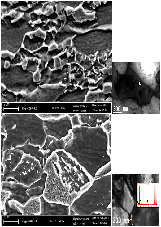
- The microstructure of hot band-9 (Heat-9) consisted of ferrite and pearlite (Fig 1a) in association with nano-sized Mo-C carbides (Fig. 1b, c). On the other hand, hot band-14 consisted of ferrite, pearlite, bainite and martensite (Fig.2a). Further, complex precipitates (Ti-Nb-Mo) C (Fig. 2b, c), rich in Ti were also observed in hot band-14 as Ti content was higher (0.031) in this band than that of the hot band-9 (0.009). The ferrite grain size of the hot bands 9 and 14 were 4.1 and 3.7μm, while ferrite area fractions were 69 and 79, respectively.
3.2. Continuous Cooling Transformation
- Heat-9From continuous cooling transformation it was observed that below 5℃/s cooling rate, ferrite, pearlite and bainite were present, while between 5℃/s and 20℃/s, the co-existence of ferrite and bainite were noticed. Further increase in cooling rate till 70℃/s showed the presence of martensite in association with ferrite and bainite, while above 70℃/s, bainite disappeared and only ferrite and martensite were present.
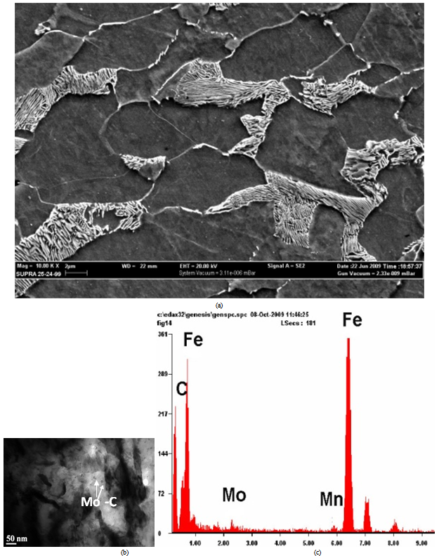 | Figure 1. (a) FEG-SEM micrographs showing ferritic-pearlitic structure, (b)TEM micrograph showing nano-sized Mo-C precipitates and (c) EDS of the precipitates in the hot band of Heat-9 |
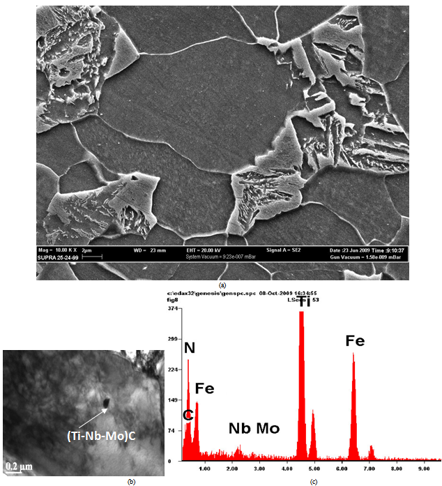 | Figure 2. (a) FEG-SEM micrographs showing ferritic-banitic-martensitic structure (b) TEM micrograph showing (Ti-Nb-Mo)C precipitates (c) EDS of the precipitates in the hot band of Heat-14 |
3.3. Continuously Annealed Samples
- Effect of cooling rate—Annealing cycles 14-CR-1 and 14-CR-2a) MicrostructureSamples that underwent cycles 14-CR-1: 10℃/s—830℃ (120s)-2℃/s-800℃-100℃/s and 14-CR-2: 10℃/s—850℃ (120s)-2℃/s-800℃-30℃/s, experienced cooling rates of 100 and 30℃/s, respectively. In both the samples ferritic-martensitic microstructure was obtained with 40% and 31% martensite fraction, respectively (Figs. 3a, b). Due to the fast cooling rate of 100 ℃/s, no new precipitates could be formed during the cooling cycle of 14-CR-1, however, as the cooling rate in 14-CR-2 was slower (30℃/s), some TiC precipitates were also formed (Fig. 3c). Further, the presence of (Ti-Nb-Mo) CN precipitates was also observed in 14-CR-2.
 | Figure 3. (a,b) FEG-SEM micrographs showing ferritic-martensitic structures for annealing cycles 14-CR-1 and 2, respectively and (c) showing the EDS of TiC precipitate in 14-CR-2 sample |
|
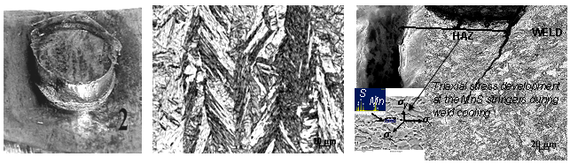 | Figure 4. (a) Showing a representative photograph of pullout button failure, (b) showing OM micrograph of predominantly martensitic structure in weld zone (c) OM micrograph showing liquation crack in the fusion line[FEG-SEM magnified view in the top-left inset] along with HAZ crack at the Mn-S stringers[bottom-left inset] for annealing cycle 14-CR-1 |
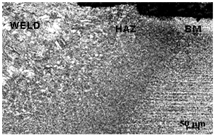 | Figure 5. OM micrograph showing defect free weld, heat affected zone (HAZ) and base metal for annealing cycle 14-CR-2 |
 | Figure 6. (a) FEG-SEM showing ferritic-martensitic-bainiticstructure and (b) showing bainite in TEM for annealing cycle 9-2-1, while (c) showing ferritic-martensitic-bainitic structure in FEG-SEM and (d) and intergranular Mo-C precipitate in TEM for annealing cycle 9-B-2 |
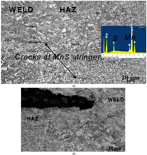 | Figure 7. (a) OM micrograph showing HAZ crack in the weldment of 9-B-1 annealing cycle while (b) showing defect free weldment for 9-B-2 annealing cycle |
4. Conclusions
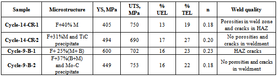
- • The steels developed were in the range of ~690-753 MPa ultimate tensile strength and 19-27% total elongation.• In all the annealing conditions the desirable plug type nugget failure was observed• Microstructure containing martensite >~ 30% in the base metal and cooling rate of >30℃/s from intercritical annealing temp., (without bainite effect) adversely affected weldability.• Introduction of optimum amount of bainite in the ferrite and martensite structure resulted in satisfactory weldability behaviour.• Nano-sized precipitates like TiC, Mo-C and (Ti-Nb-Mo)CN helped obtain desirable tensile and weld properties.• HAZ softening was found to be the main cause for HAZ cracking. HAZ softening was associated with high martensite (> 30% content) in the base metal.• In weldments where HHAZ< HWELD and HBM (HAZ softening), liquation cracks and cracks at MnS stringers in HAZ/HAZ-WM were observed.• Cycle 9-B-2 (10℃/s—780℃(120s)-2℃/s-760℃-20℃/s—470℃ (60s)-10℃/s) with ferrite, 37% bainite and martensite along with nano-sized precipitates of Mo-C resulted in the best combination of tensile properties: YS-449 MPa , UTS-753 MPa, %UEL-16%, %TEL-22% and n-0.18, and weldability with plug type nugget failure.• Stronger HAZ than weld metal in association with formable base metal resulted in favourable combination of stength-ductility-weldability.
ACKNOWLEDGEMENTS
- The author is thankful to the management of Tata Steel for permission to publish the work. Special thanks are due to Dr. Vinod Kumar, RDCIS SAIL Ranchi and IIT Madras, for strip annealing tests and TEM examination, respectively.