-
Paper Information
- Next Paper
- Previous Paper
- Paper Submission
-
Journal Information
- About This Journal
- Editorial Board
- Current Issue
- Archive
- Author Guidelines
- Contact Us
International Journal of Metallurgical Engineering
p-ISSN: 2167-700X e-ISSN: 2167-7018
2013; 2(1): 92-99
doi:10.5923/j.ijmee.20130201.14
Evolution of Microstructures and Mechanical Properties of Thermomechanically Processed Ultrahigh Strength Steels
 Abstract
 Reference
 Full-Text PDF
 Full-text HTML
S. Chatterjee, S. K. Ghosh
Department of Metallurgy and Materials Engineering, Bengal Engineering and Science University, Shibpur, Howrah, 711 103, India
Correspondence to: S. Chatterjee, Department of Metallurgy and Materials Engineering, Bengal Engineering and Science University, Shibpur, Howrah, 711 103, India.
| Email: |  |
Copyright © 2012 Scientific & Academic Publishing. All Rights Reserved.
The present study concerns the development of two low carbon microalloyed ultrahigh strength steels on a pilot scale. The dilatometric results of these steels yield flat top continuous cooling transformation (CCT) diagram along with predominantly bainitic microstructure at a lower cooling rate. The two experimentally determined CCT diagrams have further revealed that good hardenability is achievable in these steels even in air cooled condition (cooling rate ≈5℃/s). Based on the results of continuous cooling transformation, these steels were thermomechanically processed and finished at different finish rolling temperatures followed by air cooling. Variation in microstructure and mechanical properties at different finished rolling temperatures was studied. A mixture of granular bainite and bainitic ferrite along with microalloy carbide is the characteristic microstructural feature of these steels. The yield strength values in the range of 1040-1234 MPa with 1312-1439 MPa ultimate tensile strength along with 12-17% elongation have been obtained in the present investigated steels. The attainable high strength value is due to the accumulated contribution of fine grained pan-caked austenite, mixture of granular bainite and bainitic ferrite along with the presence of tiny precipitates of microalloy carbide and/or Cu rich precipitates. The steels reveal the impact toughness value in the range of 35-72J which exhibits nearly consistent fall with the lowering of testing temperature.
Keywords: Ultrahigh, Microalloyed, Steel, Microstructure, Mechanical Properties
Cite this paper: S. Chatterjee, S. K. Ghosh, Evolution of Microstructures and Mechanical Properties of Thermomechanically Processed Ultrahigh Strength Steels, International Journal of Metallurgical Engineering, Vol. 2 No. 1, 2013, pp. 92-99. doi: 10.5923/j.ijmee.20130201.14.
Article Outline
1. Introduction
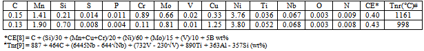
- Ultrahigh strength steels can be subdivided into low alloy steel, precipitation hardened stainless steels, maraging steels, and secondary hardening steels[1]. Basically this class of steel comprises dislocated martensitic structure with fine precipitates. The alloy steels are heat-treated by austenitizing, a subsequent cooling to room temperature or below during which most of the austenite is transformed to martensite, and finally a tempering or aging treatment is carried out during which carbides and/or other hardening particles are precipitated. These steels are ordinarily restricted to aircraft applications as landing gears, arresting hooks, fasteners, jet engine shafts, and ballistic-tolerant components as well as non-aircraft heavy duty parts as high-strength bolts, automotive drive shafts and bicycle frames etc.Low carbon steels containing 1-2% Cu have been already emerged as structural materials due to their excellent strength/ductility balance[2, 3]. Microalloying elements i.e., Ti, Nb or V, which are strong carbide former and also act as grain refiner while in solution in austenite, are also added in these steels. On subsequent cooling, these microalloying elements precipitate as carbides and/or carbonitrides which are fine enough to offer hindrance to mobile dislocations leading to a significant increase in strength. An additional strengthening is obtained from fine ε-Cu particles on ageing[4, 5]. It is noteworthy that Cu in steels causes surface hot shortness during hot deformation[6] and addition of Ni by an amount half that of the Cu content is effective for the suppression of surface hot shortness[7].In view of the above, considerable efforts have been made to develop two novel steels by thermomechanical controlled processing on a pilot scale. The low carbon content (wt%) (≈0.15) with high Mn (1.41-1.90) and marginally higher Ni (3.76-3.80) content instead of medium carbon (0.3-0.4) along with low Mn (0.5-0.8) and high Ni (2.7-3.3) containing commercial steels used earlier in the defence sector has been designed for achieving better solid solution strength together with the more than requisite through-hardening capability. This recent effort has been devoted towards the reduction of weight by achieving high strength to weight ratio together with improved weldability for the various prospective defense applications such as explosive ammunition, gun barrel, missile skins, light-weight military bridges etc. The continuous cooling transformation has been evaluated and the influence of various processing parameters on structure and properties of the steels have also been assessed.
2. Experimental
|
3. Results
3.1. Continuous Cooling Transformation
- Figure 1 depicts the CCT diagrams for the present investigated steels. The Ac3 and Ac1 temperatures of “no-Cu” steel have been recorded as 820℃ and 700℃ respectively; whereas the respective temperatures for Cu bearing steel are 825 and 706℃. The bainite start temperature (BS) has been found to be as 436-440℃ at the cooling rate of 0.5℃/s for “no-Cu” and Cu bearing steels respectively which fairly agrees with the estimated BS temperature of 406-408℃, obtained from the following equation[11].
 | (1) |
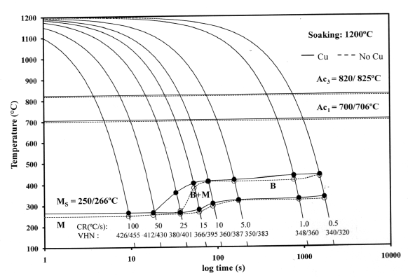 | Figure 1. The CCT diagrams for the present investigated steels |
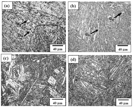 | Figure 2. Optical micrographs of both (a) “no-Cu” steel and (b) Cu bearing steel specimens cooled at 0.5℃/s, and both (c) “no-Cu” steel and (d) Cu bearing steel specimens cooled at 25℃/s showing the evolution of microstructure under continuous cooling conditions |
3.2. Microstructural Evolution
- Figures 3(a) and (b) show the bright field (BF) TEM images of air cooled “no-Cu” and Cu bearing steels, respectively which reveal mixture of granular bainite (αg) and bainitic ferrite (αb) along with high dislocation density in prior pan-caked austenite grains obtained at 750°FRT. The formation of fine parallel micro-twin substructure within the bainitic ferrite as well as interlath region parallel to the bainitic ferrite were confirmed as retained austenite(γR) in similar type of steel reported earlier[12].Figure 4(a) presents the TEM BF micrograph of “no-Cu” steel obtained on air cooling from 850℃ which reveals the dark precipitate (denoted by arrow) (≈20 nm) within the bainitic ferrite. The EDS spectra (Fig. 4(b)) from the particle denoted by arrow in (a) reveals that the particle is rich in Nb and C which indicates the formation of NbC precipitate.Figure 5(a) is the BF TEM micrograph showing the fine precipitate of darker contrast (denoted by arrow) inside the bainitic ferrite. Figure 5(b) is the EDS spectra from the arrowed fine precipitate (<50 nm) in (a). The result shows that the precipitate is rich in Cu which indicates the formation of Cu precipitate due to the adequate Cu content (> 0.6 wt%) ()[7] in the present steel. Such type of Cu precipitation during continuous cooling was reported earlier in commercial low alloy steel[13].
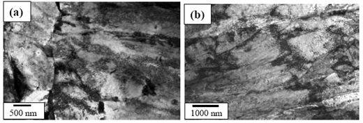 | Figure 3. TEM BF micrograph of (a) “no-Cu” steel and (b) Cu bearing steel showing mixture of granular bainite (αg) and bainitic ferrite (αb) in prior pan-caked austenite grains at 750℃ FRT |
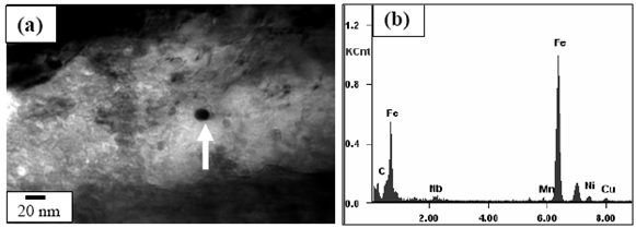 | Figure 4. (a) TEM BF micrograph showing precipitate particle within bainitic ferrite obtained at 850℃ FRT in “no-Cu” steel and (b) EDS spectra from the arrowed precipitate particle in (a) |
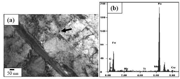 | Figure 5. (a) TEM BF micrograph showing dark precipitate (denoted by arrow) in Cu bearing steel and (b) EDS spectra from the arrowed precipitate particle in (a) |
3.3. Mechanical Properties
- Figure 6 shows the variation in yield strength (YS), ultimate tensile strength (UTS) and hardness (Hd) values of the investigated steels with the change in FRT. The minimum values of hardness (342 VHN), YS (1040 MPa) and UTS (1342 MPa) values were obtained in “no-Cu” steel at 850℃ FRT. Similarly, the minimum values of hardness (434 VHN), YS (1182 MPa) and UTS (1312 MPa) values are obtained at same FRT (850℃) for Cu bearing steel. While the variation in hardness, YS and UTS of “no-Cu” steel processed in the range of 750℃ – 850℃ are 5%, 0.67% and 7% respectively; those values are 2.5%, 4% and 3% respectively for Cu bearing steel.Figure 7 reveals the variation in percent elongation (El.) and reduction of area (RA) with the change in FRT. It is observed that percent elongation increases with the increase in FRT in both the steels. The minimum elongation of 12 to 13% is obtained at 750℃ FRT for both steels and the same increases to 17% and 14% at 850℃ FRT for “no-Cu” and Cu bearing steel, respectively. The percent RA for both the steels follow nearly the same trend as mentioned for percent elongation.Figure 8 shows the variation in impact toughness values of both the steels processed at different FRTs with the various testing temperatures. It is noticed that generally impact toughness decreases with the decrease in testing temperature. The “no-Cu” steels record the impact toughness values in the range of 35-63J, whereas Cu bearing steels reveal in the range of 41-72J. It is evident that “no-Cu” steel has revealed lower impact properties in comparison with those of the Cu bearing steel within the range of testing temperature. While no distinct transition temperature range is recorded for the “no-Cu” steel, the Cu bearing steel samples exhibit a distinct transition temperature range from -20℃ to -40℃. In the case of “no-Cu” steel samples, a gradual fall in impact toughness value is noticed with the lowering of testing temperature except for 850℃ FRT. On the other hand, the upper and lower shelf energy values vary in a close range for Cu bearing steel.
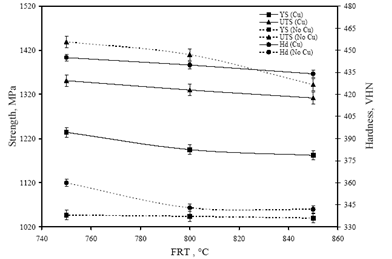 | Figure 6. Variation in yield strength, ultimate tensile strength and hardness values with the change in FRT |
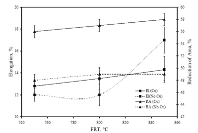 | Figure 7. Variation in percent elongation and reduction of area with the change in FRT |
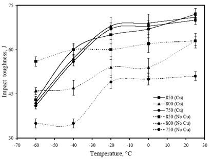 | Figure 8. Variation in impact toughness values with the testing temperature |
4. Discussion
4.1. Austenite Conditioning
- Austenite conditioning was performed by controlling the austenitising temperature or by the amount of deformation in the recrystallisation or non-recrystallisation region. In the present study, high soaking temperature (1200℃) and time (3h) were employed to ensure the maximum dissolution of microalloy carbides and carbonitrides in austenite. As the solubility limit of TiN calculated from the available references[14, 15] at 1200℃ is 4.365×10⁻⁶ (wt%)2 which is very low as compared to the[Ti][N] solubility product obtained in the range of 3.24×10⁻⁴ (wt%)2 to 4.16×10⁻⁴ (wt%)2 for the present investigated steels, TiN/TiCN particles formed are likely to remain undissolved during reheating at 1200℃. However, the calculated solubility limits of TiC (9.9×10⁻³) or NbC/NbCN (4.5×10⁻³) are being rather high at this soaking temperature, it is expected that TiC, NbC or NbCN formed during cooling of the ingot will be dissolved again during slab reheating. In this context, it may be mentioned that as TiC has higher solubility than NbC or NbCN, it is expected that the latter will first come out from the solution.Misra et al.[16] studied microstructure evolution in industrially processed hot rolled Nb-Ti microalloyed steel. The carbide forming elements Ti and Nb retard recrystallization during finish rolling and consequently a pan-caked microstructure is formed that promotes grain refinement during austenite to ferrite transformation. About 90% deformation in the non-recrystallization region (stage II and III; Tnr = 998 and 1161℃) results into the formation of pan-caked grains which restrict the size of bainite obtained on air cooling. It needs to be mentioned that for the carbon equivalent (CE) in the range of 0.40-0.43% (Table 1), there is a less potential for cracking in the heat affected zone (HAZ) on flame cut edges and welds of the present steels.
4.2. Multiphase Structure
- On air cooling from the various FRTs, the deformed austenite has been transformed into granular bainite and bainitic ferrite with dislocated substructure (Fig. 3). The dislocation introduced into the bainite is a consequence of product of transformation. It is noteworthy, that the well deformed austenite prior to cooling leads to the formation of crystalline defects which contributes to the formation of fine bainite structure.The microalloying elements i.e., Ti, Nb remain in solution at the soaking temperatures (1200℃) and upon cooling they combine with C and N to form carbide/carbonitride precipitates. With a further lowering in temperature the supersaturation increases and precipitation begins e.g., NbC precipitates (Fig. 4(a)) form during processing of the slab. It can be considered that the fine microalloy precipitate (≈20 nm) (Fig. 4(a)) and Cu rich precipitate (<50 nm) (Fig. 5(a)) formed after rolling in the non-recrystallization region. These precipitates are expected to be incoherent with the steel matrix. The precipitation hardening resulting from these nano-sized particles is significant in case of high strength steel.
4.3. Structure-Property Correlation
- On air cooling, mixture of granular bainite and bainitic ferrite along with microalloy precipitate is obtained and tested to reveal higher level of hardness 434-445 VHN, 1182-1234 MPa YS and 1312–151 MPa UTS along with lower 13-14% elongation and comparable RA (56-58%) and higher level of impact toughness value (41-72J) as compared to those of the “no-Cu” steel. Highly dislocated bainite (Fig. 3) along with microalloy carbide (Fig. 4(a) increases the strength of the steel. A major strengthening comes from the contribution of Cu rich precipitates (Fig. 5(a)) in Cu bearing steel.A modified version of the Hall-Petch equation (2) has been used to estimate the combined effect of dispersion strengthening (σp) conferred by incoherent particles and by dislocation strengthening (σd). The combination of σp+σd is based on the strong interaction of dislocation and particles. Equation (2) shows that by subtracting the ferrite lattice friction stress and carbon + nitrogen in solution (σ0), together with the solid solution (σs) and grain size strengthening (σg) components from the measured yield stress (σy), values of σp+σd can be calculated. Cracknell and Petch[17] suggested that σ0 (given in equation (3)) depends upon the frictional forces exerted by solute atoms and precipitates on the dislocation arrays that propagate the yield. The value of σ0 increases when the concentration of carbon + nitrogen in solution is increased. Pickering and Gladman[18] and Leslie[19] extensively studied the substitutional solid solution strengthening effects in carbon steel and iron, respectively and suggested that σs can be estimated using equation (4). Morrison and Chapman[20] investigated the effect of grain size on yield stress in terms of equation (5).
 | (2) |
 | (3) |
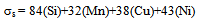 | (4) |
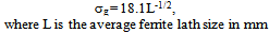 | (5) |
5. Conclusions
- 1. Two microalloyed ultrahigh strength steels have been successfully produced on a pilot scale. The continuous cooling transformation behaviour of both steels has been studied. In both steels, flat top CCT diagrams along with bainite microstructure have been observed at a lower cooling rate.2. “No-Cu” steel reveal mixture of granular bainite and bainitic ferrite along with the NbC precipitates. On the other hand, Cu bearing steel shows similar microstructural features like “no-Cu” steel and additional Cu rich precipitate.3. Strength level of 1040-1047 MPa yield strength and 1342–1439 MPa ultimate tensile strength along with 12-17% total elongation have been obtained without Cu addition, whereas higher yield strength in the range of 1182-1234 MPa and lower range of 1312–1351 MPa ultimate tensile strength along with lower level of 13-14% total elongation have been obtained in Cu bearing steel.4. “No-Cu” steel reveals the impact toughness value in the range of 35-63J which is lower compared to those of Cu bearing steel (41-72J) under similar processing condition.