-
Paper Information
- Next Paper
- Previous Paper
- Paper Submission
-
Journal Information
- About This Journal
- Editorial Board
- Current Issue
- Archive
- Author Guidelines
- Contact Us
International Journal of Metallurgical Engineering
p-ISSN: 2167-700X e-ISSN: 2167-7018
2013; 2(1): 69-78
doi:10.5923/j.ijmee.20130201.11
Deterministic Approach for Microstructurally Engineered Formable Steels
 Abstract
 Reference
 Full-Text PDF
 Full-text HTML
G. Anand1, S. Datta2, P. P. Chattopadhyay1
1Department of Metallurgy and Materials Engineering, Bengal Engineering and Science University, Shibpur, Howrah, India
2Devbhoomi Institute of Technology, Dehradoon, Uttarakhand, India
Correspondence to: P. P. Chattopadhyay, Department of Metallurgy and Materials Engineering, Bengal Engineering and Science University, Shibpur, Howrah, India.
| Email: |  |
Copyright © 2012 Scientific & Academic Publishing. All Rights Reserved.
Steel design is traditionally governed by the imprecise knowledge acquired from the experimental efforts occasionally invoking the empirical, physical and thermodynamic models supported by numerous assumptions and boundary conditions. The available frameworks are independently inadequate for complete and deterministic composition-process-microstructure-property (CPMP) correlation. The situation thus calls for judicious integration of the potential techniques with the capability of a priori prediction/optimization of the complete system. In view of the above the present article aims to provide a bird’s eye view of the deterministic approach invoked so far in the traditional framework of design and development of formable steels. An attempt has also been made to propose the scheme for hybridization of the potential techniques for describing the complete CPMP correlation in the production schedule of hot strip coil.
Keywords: Steel, Microstructure, Property, Design, Technique Blends
Cite this paper: G. Anand, S. Datta, P. P. Chattopadhyay, Deterministic Approach for Microstructurally Engineered Formable Steels, International Journal of Metallurgical Engineering, Vol. 2 No. 1, 2013, pp. 69-78. doi: 10.5923/j.ijmee.20130201.11.
Article Outline
1. Introduction
- Progress in steel technology is primarily driven by the mounting performance demand in application areas,emergence of competitive materials and increasing stringency in the environmental regulations. Over the years, the experimental and theoretical capabilities have advanced from one paradigm to other as identified by compositional,thermo-mechanical, microstructural and deformation attributes.At the initial phase, majority of compositionally designed steels were designated by single phase ferritic, pearlitic, austenitic or martensitic microstructures. Since 1970s, major emphasis has been on grain refinement by tailoring the thermo-mechanical schedule. The demand for weight reduction of the vehicle body structure evolved the concepts of composite microstructure coupling hard and soft phases as for example, in dual phase steel.In the early 1990s, the ferritic microstructure containing bainitic phase with adequate amount of retained austenite was found attractive in respect of strength-ductity balance. Such microstructures were identified as TRanformation induced Plasticity (TRIP)-aided steels. A similar class of microstructures developed by subjecting the partitioning of alloying elements from martensite to austenite between martensite-start (Ms) and finish (Mf) temperatures are designated as “Quench and Partitioning Steels”.Development of such TRIP-aided steels relies on the dynamic microstructure evolution during plastic deformation. The response of austenite to strain and strain rate at different temperatures attracted major attention in the design of fully austenitic high manganese steel which offers most attractive strength-ductility-formability combination.At this juncture, it may be worthy to take an account of the model capabilities and their integration with an aim to develop an integrated and deterministic design framework.
2. Empirical and Physical Approach
2.1. Microstructural Evolution
- Fig. 1 presents the mapping of the microstructures developed for high strength application of formable steels based on the popularly known ‘banana’ diagram. The strain hardening and formability parameters are also incorporated in the figure. The diagram depicts the properties of three single phase microstructures namely, ferritic, martensitic and austenitic, and the evolution of composite microstructures obtained by combining two or three of the phases at different proportions. Among such multiphase varieties, strength of the DP and TRIP steels and constrained by the presence of intercritical ferrite (>60%), while the single phase austenitic steels requires addition of large amount alloying elements (15-25%). The austenite-bainite/martensitic verities of steel exhibit the possibility of achieving attractive strength-toughness formability balance and have drawn major attention in recent time. The empirical and physical frameworks available for understanding the microstructural evolution of established varieties of steels are summarized below in Fig. 1.
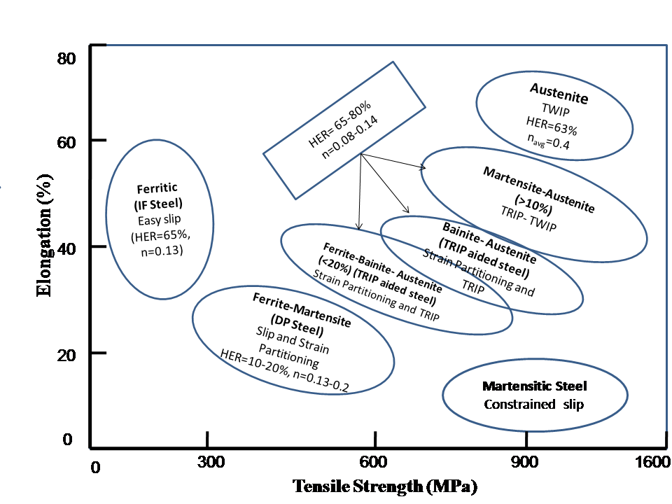 | Figure 1. Microstructure based mapping of formable steels |
2.2. Ferritic Microstructure
- Quantitative understanding of hotdeformed/thermo-mechanically processed low carbon low alloy ferritic steels concerns austenite recrystallization and austenite to ferrite transformation. The initial grain size of austenite determines the nucleation rate and recrystallization kinetics. Generally, recrystallization kinetics is expressed in terms of so called “Johnson-Mehl-Avarami- Kolmogorov (JMAK) theory[1-5]. Toloui et al[6] expressed JMAK equation for the time for 50% recrystallization (t0.5) as:
 In this equation, t0.5 is correlated to the processing history and may be calculated by empirical relationship as[6]:
 where A, E, F, a, b and c are material constants, d0 the initial grain size, ε the strain, Qrex the activation energy for recrystallization, Rg the universal gas constant, Trex the recrystallization temperature and Z is the Zener–Hollomon parameter. The recrystallized fraction of austenite under non-isothermal condition is determined by incorporating the additivity rule. According to the Scheil’s additivity rule[7], the reaction starts when the sum of the ratios of reaction starts time (
 ) reaches unity, which may be written as:
 Where,
  represents the incremental hold time at temperature
 . The phase transformation from austenite to ferrite in the intercritical region has also been treated under the JMAK framework incorporating the Scheil’s additivity rule. In the case of increased mole fraction of the substitutional solute, Onsager’s extremel principle[8-9] has been applied. For estimation of the Gibbs energy (G) of the system as:Where,
  denotes the molar volume, i from 1 to n are the labels for the substitutional components and the interstitial components are labeled by i ranging from the n + 1 to m. The volume of the system is V , and xi and µi are the mole fraction and the chemical potential of the components.
2.3. Multiphase Microstructure
- The common practice in development of the ferrite based multiphase microstructure of such steel is intercritical annealing (ICA) of the hot-rolled pearlitic steel with an aim to achieve ferritic and alloy enriched austenite. The intercritical austenite is subsequently transformed to martensite (Dual Phase steel) or bainite (TRIP steel). During inter critical annealing, the first step comprises the nucleation of austenite at ferrite-pearlite interface and growth of austenite into pearlite, until dissolution of pearlite is complete. This stage is followed by austenite growth controlled by Mn diffusion and final equilibrium with Mn diffusion in austenite. The Mn distribution in austenite and ferrite during intercritical annealing involves the following two processes[25]:(i) Mn moves from ferrite to the ferrite-austenite grain boundary and forms Mn rich rim.(ii) The Mn in Mn-rich rim at the ferrite-austenite boundary diffuses into austenite until final equilibrium is reached and Mn gradient in austenite is eliminated. The diffusion analyses for these two processes combine with mass balance
 (
( represents the area occupied by ferrite, austenite and Mn-rich rim respectively)The equation thus provides Mn redistribution and partitioning coefficient at any time during austenite grain growth.
2.4. Martensitic Transformation (Dual-phase Steels)
- The martensite start or Ms temperature of the intercritical austenite may be calculated by least square fitting martensitic transformation data as determined from dilatometric experiments to the exponential Koistenin-Marburger (K-M) equation given as:
 Where, f and T are the martensite fraction and the absolute temperature, respectively[11]. Fraction transformed fm is obtained from slope of dilatation (ν) temperature before and after the Martensitic temperature is determined. The determined Ms temperature as a parameter of the linear fitting of –ln (1- fm) versus temperature, using exponential K-M equation expressed as
 . From the measured Ms temperature, the carbon content of the intercritical austenite may be calculated by using the following empirical equation[12-13]:
 The following exponential expression for Ms temperature has been proposed[14], as influence of carbon at higher concentration is less[15], leading to following modified equation[16]:
2.5. Bainite Transformation (TRIP-aided steel)
- Bainite formation was envisaged to occur at a temperature just below T0 line, which is the locus of transformation temperatures where both bainitic ferrite and austenite of similar composition have identical free energy[16]. The effect of substitutional solutes on reducing the
 temperature (
 ) is given by[17]:
 The
The  curve for plain carbon steel is given by[18]:
 Where, xc is the atomic fraction of carbon.The volume fraction of austenite is also the function of transformation temperature. The maximum volume fraction of retained austenite may be given by following relationship:
 Where, Ttransf is bainite transformation temperature.The transformation of austenite to bainite when fitted to JMAK equation shows two slopes in the plot of
  versus
 . This indicates that the change in the transformation temperature
 2.6. High Manganese Austenitic Steel
- The transformation of austenite during straining is important depending upon the stacking fault energy (SFE) or. The transformation of austenite during deformation may take following routes:1. For,
 , martensitic transformation occurs either by formation of
  martensite or even at lower SFE by formation of
  martensite following the route
  [19]. 2. For,
  , twinning is the favorable phenomena[20-21].3. For,
  , planer glide of dislocation determines the plasticity and strain hardening[19]. The important aspect of the phase evolution of TWIP steel concerns the variation of stacking fault energy (SFE) with appropriate adjustment of alloying elements, particularly in respect of Mn, Al and Si. In this regard, Mn[20] and Al[21] decrease the SFE, while Si increases the SFE[22]. The measurement of SFE by thermodynamic approach was proposed by Olson and Cohen[23] as:
 Where,
  is the molar density along
  plane,
  represents the molar free energy of the austenite to ferrite transformation and represents
  the surface energy of the austenite-ferrite interface. The model accounts for the change in the Gibbs energy of each element upon the ε-martensitic transformation. The
  term include the first order interaction between various elements and change in Gibbs energy due to the magnetic contributions to the Gibbs energy, including paramagnetic toanti-ferromagnetic transitions of the austenite and the -martensite.
3. Deformation Behavior and Tensile Property
- The yield strength
 as a function of ferrite content
 , ferrite grain size
 , pearlite spacing
 , and compositional details such as Mn content, Si content and free nitrogen content is expressed as[24]:
 Similarly, the tensile strength σUTS is expressed as[24]:
 The yielding and straining of high strength low alloy steel (HSLA) includes the additional influence of precipitation strengthening by microalloying elements. The yield and ultimate stress increment due to precipitation hardening σppm in the case of V-microalloyed steels is represented as[24]:
 The stress strain behavior of single phase microstructures may be approximated by Mecking-Kocks model[25-26], where the evolution of dislocation density depends upon the competitive hardening and softening (due to recovery).According to Mecking-Kocks theory, the evolution of plasticity results from the competition between rate of production of dislocation
  and rate of annihilation
 . The strain hardening due to accumulation of dislocation, is given as:
 Where,
  is the mean free path of the dislocation,
  is the burger vector of the dislocation,
  is the grain size,
  is the constant and
  represents the dislocation density. The dislocation annihilation term, corresponding to the recovery, is represented as:
 Where, f is the dislocation annihilation parameter. The expression for the evolution of dislocation density is obtained as:
 Where, is the Taylor parameter, independent of grain size and represents strain. Model for tensile behavior of dual phase microstructure was presented by Tomata et. al.[27], which is general in nature, as it considers the internal stress produced by the inhomogeneous deformation. It is applicable to the case where, second phase (hard) is randomly distributed as grains of ellipsoidal shape. The stress-strain behavior of the each constituent phase of TRIP steel is also determined by considering the Mecking-Kocks model[28]. The model for M/A constituent is determined by calculating the strain-induced martensitic fraction, as the initial austenite island transforms into M/A constituent, the separate behavior of the martensite and austenite is taken into consideration and coupled to the strain dependent evolution of the phase ratio of the M/A constituents. The martensitic volume fraction
  may be determined from the Olson-Cohen formulation[28] as:
 where,
  is related to the volume fraction of shear bands and
  is related to the number of shear interactions per unit volume of the austenite and is the constant having the value of 2, for TRIP-aided steels[28]. The grain size of the retained austenite
  is also the function of the volume fraction of the strain induced martensite, which may be given as:
 Where,
  is the initial grain size of the austenite. The stress-strain behavior of the austenite may be modeled using Mecking-Kocks Model, when
  is considered to be equal to
 . Thus,
 The stress strain behavior of the martensite under static deformation condition has been developed by Rodriguez and Gutierrez[29]:
 Where, L is the martensite lath width. Now, Gladman-type power law[30] is used to define the stress-strain behavior of the M/A constituent, as given by:
 Where fα’ is the voume fraction of martensite and σγ and σα’ are the stress in austenite and martensite repectively. The value of n’ is determined by fitting stress-strain curves to the experimental data. Fig.2 shows the schematic representation of this scheme.
 | Figure 2. Decomposition of multiphase TRIP steel and application of Mecking-Kocks model and Stress mixture law for determination of stress-strain curve |
 Where, σm is the flow stress of the untwinned austenite matrix, µ the shear modulus, b the burger vector, n the number of dislocation in the pile-up and t the mean distance between adjacent twin.The second approch of the modelling concerns the dynamic reduction of mean free path of dislocation by the twin boundary[35-36], It also considers the Mecking-Kocks theory to relate the evolution of the statistically stored dislocation and it considers isotropic hardening behavior of the material. Here, the mean free distance has been modified and written as[35-36]:
 The average twin spacing is an inportant parameter for the deformation of TWIP steel. The same may be related to the twin volume fraction by the following relation[37]:
 Where, F is the twin volume fraction and e is the average twin thickness, which is independent of strain and of the order of one micrometer.The twinning kinetics may be derived from the Olson-Cohen’ assumption[38], given as:
 Where, is a function of SFE, which increases when SFE decreases. By integrating, the twin volume as a function of strain is obtained as:
3.1. Damage Behavior
- The damage behavior of the formable multiphase steels has been successfully modeled by the Finite Element Analysis (FEA)[39] involving an adequate definition of the representative volume element (RVE). The RVE must be large enough to include the sufficient number of microvoids and microcracks, but at the same time small enough for stress and strain rate to be considered homogenous[40-41]. Simulations of dimple fracture mechanisms in TRIP steels have been carried out using GTN(Gurson-Tvergaard-Needleman) heory[42]. The GTN model considers that primary voids will grow after plastic deformation. Additionally, secondary voids emerges at characteristic equivalent strain. In contrast, cohesive zone model (CZM), based upon separation law, has been used to describe the cleavage failure mechanism[43]. Moreover, the CZM is applied in the RVE between phases, to consider the interface de-bonding in the microstructure. When the normal and tangential components of separation reaches a critical values, and respectively, the continuum elements connected by cohesive elements becomes disconnected. The integral of traction Γ0 as a function of the separation, up to the critical separation δ0 provides the energy dissipated by the cohesive element at failure. The failure criterion for the cohesive zone is defined by the integration function, expressed as[44],

4. Computation Approach of Steel Design
4.1. Thermodynamic Tools
- Presently, several thermodynamic softwares are available for calculation of the thermodynamic parameters in steel. The salient features of the popularly used softwares like MTDATA[45], ThermoCalc[46] and DICTRA[47] are given below. The MTDATA software allows equilibria to be calculated for the multicomponent systems from critically assesses data for their component binary and ternery subsystems. The application of MTDATA in steel research is useful in the areas of calculation of thermodynamic parameters of alloying elements, study of behaviors of particular alloying element under the influence of other alloying elements, approximation of solute partitioning effect, driving force for precipitation and phase composition calculation[48-49].The ThermoCalc software has been developed for systems exhibiting complex heterogeneous interactions for strongly non-ideal solution phases[50-51]. Thermo-Calc allows explicit conditions on individual phase compositions or configuration while most of the similar software handles conditions on the overall composition only. The flexible way to set conditions is particularly useful when Thermo-Calc is used as a subroutine package in application programs, for example, in microstructure evolution or process simulations.In parallel with the development of ThermoCalc, software for simulation of DIffusion Controlled TRAnsformations, DICTRA was also developed. It is closely linked with the ThermoCalc software, which provides all the necessary thermodynamic calculations. Some areas of application includes, homogenization of alloys[52], carburization and decarburization of steels[53], nitriding of steels[54], austenite/ferrite diffusional transformations in steels[55], calculation of TTT-diagrams[56] etc.
4.2. Microstructural Simulation Techniques
- In the efforts on understanding the genesis of structure-property correlation, sharp interface simulation techniues like Cellular Automaton (CA) and Monte Carlo-Potts (MC) technique have found usefull application for prediction of morphology of the grains and to follow the nucleation and growth of the individual grains and their mutual interaction. The microstructural simulation models concerning the kinetics of the evolution may be broadely calssified into two categories, Firstly sharp interface models and secondly diffused interface models[57].In conventional modelling techniques, sharp interface is considered, with sudden change in the field variable or order parameter (when the state of the system is defined by the single variable defined as the order parameter). The difference may be conceptually visualized from the Fig. 3.The phase field simulation is basically a meso-scale simulation technique, based on diffused interface approach, considering a number of grains. The shape and mutual distributions of the grains are represented by the set of field variables, that are continuous in space and time[57]. Within a grain, the values of the phase field variables are constant, while at the interface between the two grains the phase field variables gradually vary between their values in neighboring grains. The equation for the evolution of phase field variables are derived on the basis of the chemical thermodynamics and kinetics. However, they do not deal with the behavior of individual atoms, so material properties must be introduced in the model through phenomenological parameters that are determined on the basis of the experimental and theoretical information.In steel research, Phase field simulations has been applied to the wide variety of applications including the solidification[58], diffusive[59-60], and non-diffusive transformations[61-62].
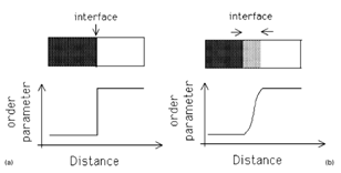 | Figure 3. (a) Sharp interface approach and (b) diffused interface approach[57] |
4.3. Soft Computation Approach
- In recent times, a group of soft computing techniques have been employed in the efforts ofcomposition-process-microstructure-property correlation of steel based on the available information and imprecise knowledge. It is imperative to present here some of the potential techniques
4.4. Fuzzy Inference Systems
- A fuzzy set is a set without a crisp or clearly defined boundary. The set contains elements with only a degree of membership, as in fuzzy logic the truth of any statement becomes a matter of degree. The membership value (or degree of membership) of each point in the input space is mapped to a value between 0 and 1 by a membership function (MF). Fuzzy linguistic descriptions are formal representations of systems made through fuzzy IF-THEN rules. Fuzzy IF-THEN rules are in the form ofIF (x1 is A1, x2 is A2, ……, xn is An) THEN (y1 is B1, y2 is B2, ……, yn is Bn) where the linguistic variables xi, yj take the values of fuzzy sets Ai, Bj respectively. One of the most effective applications has been found in prediction of properties of TRIP-aided steels based only on the imprecise metallurgical knowledge[63].
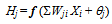
4.5. Artificial Neural Network
- An ANN model consists of a set of interconnected neurons having computing capabilities. The neurons interact with each other through connection strength, called weights. The process of adjusting connection weights with the objective of getting a better response is called learning or training.The inputs Xi are multiplied by weights Wji for a hidden node Hj; summation of all the WjiXi is then added to a bias value θj and finally operated by a suitable transfer function (f). The operation may therefore be written as
 | (1) |
 | (2) |
4.6. Genetic Algorithm
- Genetic algorithm (GA), is a evolutionary algorithm based stochastic global search method capable to mimic the principles of natural selection and natural genetics[72] to find the best solution for a specific problem. GA operates on a population of feasible solutions to produce better approximations to a solution applying the principle of survival of the fittest.
4.7. Technique Blends
- The aforesaid techniques concerns particulartransformation and/or microstructural state and are inadequate for complete description ofcomposition-process-microstructure-property correlation under a given manufacturing schedule. The robustness as well as the inherent complexity and/or nonlinearity embedded in the process often limit the applicability of a single technique. In the real world such limitations have been frequently circumvented by invoking the composite/hybrid approach. In this approach a given problem is judiciously segmented into different components and are solved by more than one techniques employed in parallel or sequential manner. In view of the above, an attempt has been made here to present a hypothetical framework forcomposition-process-microstructure correlation in the case of continuously cooled hot strip coils by combining several models and computational techniques. In the hot strip manufacturing, the first stage involves deformation of austenite followed by dynamic, metadynamic and static recrystallization of austenite grains. Here, the input variables are austenite grain size before deformation, temperature and amount of deformation (dislocation density) while the output variables are size of the recrystallized austenite grains and corresponding temperature. Fig. 4 presents the scheme for modeling the dynamic, metadynamic and static recrystallization behavior. While the empirical correlations predict the grain size and volume fraction of austenite, the thermodynamic tools are capable to model the microstructures. In the case of low alloy addition and simple microstructure, CA and MCP methods are found effective when supported by appropriate thermodynamic conditions developed by taking the amount of deformation and temperature into account. The kinetic conditions may also be presented by considering the JMAK equation along with the additivity rule. For higher level of alloy additions, applicability of techniques like CA and MCP techniques are limited. In such occasions data driven techniques like ANN are found to be the appropriate tool. For the emerging alloys where data is sparse, rule based technique like fuzzy inference system may be considered.Output from the model presented in Figure 4, i.e., recrystallized volume and grain size of austenite and the corresponding temperature profile, is employed as the input variable for modeling the microstructure evolution during cooling on the run-out table followed by coiling, where ferritic and bainitic transformation of austenite is depicted by the concerned CCT diagram. Recently ANN technique has been successfully employed for prediction of CCT diagram for a given alloy[66]. Correspondingly, Thermal profile at this stage is determined by using the FEM. From the predicted CCT diagram transformation temperatures are determined for a given cooling profile, which provide the necessary thermodynamic conditions for simulation of microstructure by CA.Phase evolution during coiling may effectively be solved in a similar manner to that of the run out condition. However, the role of contact pressure and curved profile of the coil make the heat dissipation model more complex than the run out table. In such cases controlled volume method perform more effectively than FEM.Once the microstructural evolution of the hot strip coil predicted successfully for a given composition and process variables, the same can be subjected to estimation of mechanical properties by invoking the M-K models and/or rule of mixture as depicted in Fig. 2.Hot strip production has been practiced in industries over the years and the information in the area is abundant. In such cases GA may be successfully employed to minimize the error between the experimentalcomposition-process-property and predicted composition-process-microstructure correlation which make the prediction more reliable. Once the model is established with adequate reliability, the same can be used for multi objective optimization employing GA by invoking the compositional and mill constraints and desirability of various properties. In the effort to develop a comprehensive model for predicting mechanical properties from primary variables, viz. composition and rolling parameters, considering all the deformation and cooling schedule, deterministic models may fail to consider some particular features e.g., grain boundaryprecipitation/diffusion. Such issues can be mitigated by embedding uncertainty and imprecise knowledge through fuzzy logic.
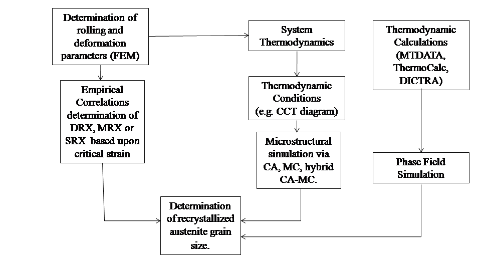 | Figure 4. Model for recrystallization during deformation in hot-strip mill |
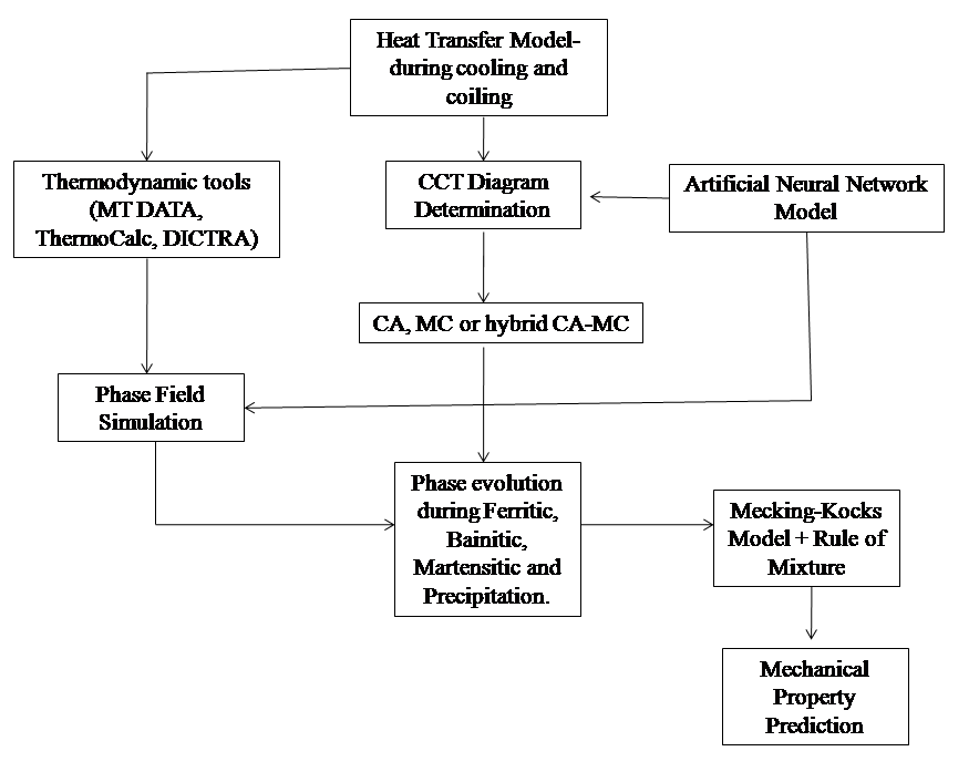 | Figure 5. Model for phase transformation during cooling and coiling in hot-strip mill |
5. Summary
- The review of different models available for deterministic understanding of the path of microstructure and mechanical properties evolution in steel may be summarized as following:1. Most of the model available so far stand in isolation and are independently inadequate to describe the complete spectrum of thecomposition-process-microstructure-property correlation in the time scale of the concerned process.2. Large volume of information generated through industrial practice and research efforts over the years remain unutilized in the sense that significant amount of latent knowledge embedded in the volume of information remains unexplored.3. Judicious hybridization of the physical and empirical models as well as the deterministic and fuzzy models may evolve the reliable framework for describing the complete path of microstructural evolution and correlating the same with mechanical properties.4. Emergence of the potential simulation technique owing to the recent advancement in computing techniques and capability need to be effectively incorporated in the hybrid framework.5. The successful hybridization of the potential techniques may develop the capability of a priori design of microstructurally engineered high performance steel to be manufactured under continuous cooling condition ‘right at first time’.