-
Paper Information
- Next Paper
- Previous Paper
- Paper Submission
-
Journal Information
- About This Journal
- Editorial Board
- Current Issue
- Archive
- Author Guidelines
- Contact Us
International Journal of Metallurgical Engineering
p-ISSN: 2167-700X e-ISSN: 2167-7018
2013; 2(1): 52-55
doi:10.5923/j.ijmee.20130201.08
Refinement of Ferrite Grain Size Near to the Ultra-Fine Range by Single-Pass and Multi-Pass Thermo-Mechanical Compression
 Abstract
 Reference
 Full-Text PDF
 Full-text HTML
D. Chakrabarti1, S. Patra1, A. Haldar2, Vinod Kumar3
1Department of Metallurgical and Materials Engineering, Indian Institute of Technology (I.I.T.), Kharagpur, West Bengal 721 302, India
2Steel Metallurgy Division, Swinden Technology Centre, Tata Steel Europe,Moorgate Rotherham, UK
3R&D Centre for Iron and Steel, RDCIS, SAIL, Ranchi
Correspondence to: D. Chakrabarti, Department of Metallurgical and Materials Engineering, Indian Institute of Technology (I.I.T.), Kharagpur, West Bengal 721 302, India.
| Email: |  |
Copyright © 2012 Scientific & Academic Publishing. All Rights Reserved.
Single-pass and multi-pass deformation schedules have been applied to low-C microalloyed steel containing Nb, Ti and V. Heavy deformation (~80%) in a single pass, just above or below the austenite-to-ferrite transformation temperature (Ar3), followed by slow-cooling (@1°C/s) of the samples to room temperature, resulted in the formation of ultra-fine ferrite grain structures with average grain size of ~2 to 3 μm. Ferrite grain size variation observed in the ultra-fine grained steel can be explained in view of several metallurgical phenomena such as, static and dynamic strain-induced austenite (γ)→ferrite (α) transformation, dynamic recovery, dynamic recrystallisation, and grain-growth of ferrite. Multi-pass deformation schedule can also refine the ferrite-grain size close to the ultra-fine range (~3 μm) provided more than 50% reduction is applied in the finishing stage, between Ae3 and Ar3 temperatures.
Keywords: Ultra-Fine Grain, Single-Pass, Multi-Pass Deformation, Plane-Strain Compression, Ferrite Grain Size, Grain Size Variation, Micro-Texture
Cite this paper: D. Chakrabarti, S. Patra, A. Haldar, Vinod Kumar, Refinement of Ferrite Grain Size Near to the Ultra-Fine Range by Single-Pass and Multi-Pass Thermo-Mechanical Compression, International Journal of Metallurgical Engineering, Vol. 2 No. 1, 2013, pp. 52-55. doi: 10.5923/j.ijmee.20130201.08.
Article Outline
1. Introduction
- Beneficial effect of ferrite grain refinement on improving the strength and toughness of low-carbon steel is well established and that was the drive behind the industrial development of thermo-mechanical controlled processing (TMCP) of microalloyed steels, containing Nb, Ti and V[1]. Application of advanced TMCP refined the ferrite grain size down to the ultra-fine range (≤ 3 μm)[2-4]. The effects of prior austenite (γ) grain size, deformation temperature (Tdef), true strain (ε), strain rate (), and cooling rate (CR) on the formation of ultra-fine ferrite (UFF) grains, in low-carbon steels, have been studied extensively[2-9]. Use of finer γ-grain sizes (14-20 μm), large strain deformation (ε > 0.5) just above the Ar3 temperature (750-850°C) at a high strain rate (>0.1/s), followed by rapid cooling (CR > 30ºC/s) of the samples can achieve homogeneous distribution of UFF grains through dynamic strain induced austenite (γ)→ ferrite (α) transformation, DSIT[2-9]. In an industrial rolling mill, the application of single and heavy deformation pass at a low temperature, with high and fast CR, is however, difficult due to the requirement of excessive rolling load (resulted from the high material flow-stress), precise temperature control, and water-cooling unit[2]. Therefore, single-pass, as well as multi-pass deformation schedules has been performed in the present study, keeping the total deformation same, and the samples were cooled down at a slow-rate (1°C/s). The average ferrite grain size, grain size distribution, nature and distribution of the second phase and texture developed in both the schedules have been compared. Fine-scale grain size variation observed in the ultra-fine grain structures has also been studied as this aspect is yet to be understood fully.
2. Experimental Details
- Plane-strain compression testing has been carried out on the samples (10×15×20 mm rectangular blocks) of a Nb-Ti-V microalloyed steel, Table 1, using the Gleeble®3500® simulator. Single-pass and multi-pass deformation schedules, having different amount of roughing, intermediate and finishing deformation passes have been applied at different temperatures, varying between 1050°C and 650°C. Schematic of a typical single pass deformation schedule is shown in Fig. 1, where the deformed samples were soaked at 1200°C, cooled at 1°C/s to the deformation temperature and either water-quenched or continued to cool down at a slow-rate (1°C/s) after the compression. Total amount of reduction (~80%) remained the same. Samples have been prepared for the metallographic studies and investigated by optical microscope, scanning electron microscope (EBSD), transmission electron microscope (TEM) and electron backscattered diffraction analysis (EBSD).
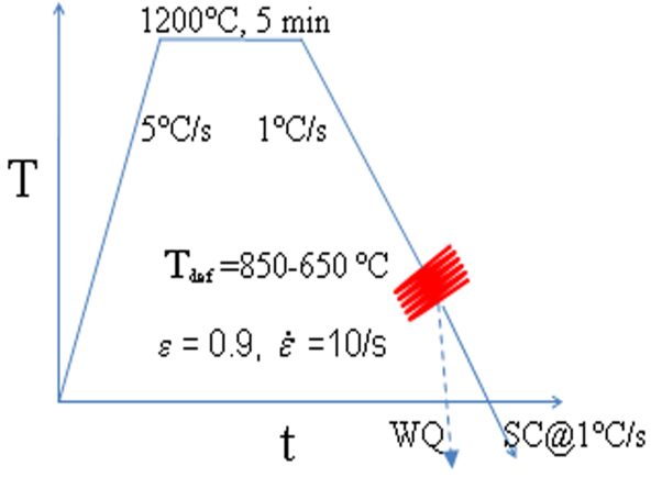 | Figure 1. A single-pass, thermo-mechanical processing schedule performed in Gleeble®3500 |
|
3. Results and Discussion
- Applying heavy deformation in a single pass, just above the austenite-to-ferrite transformation temperature (Ar3), followed by slow-cooling (@1°C/s) to the room temperature resulted in the formation of UFF grain structures, Fig. 2, with average α-grain size between 2 and 3 μm and the largest grain sizes extending up to ~10 to 12 μm. Water quenching just after deformation prevented the coarsening of UFF grains, offered finer average grain size (<2μm), and restricted the largest grain sizes to under 6 μm[10]. Although the ferrite grain structures appeared homogeneous in slowly cooled samples, careful observation revealed the presence of alternate bands of coarse- (5 to 10 μm) and fine-α grains (<1 to 3 μm)[10].
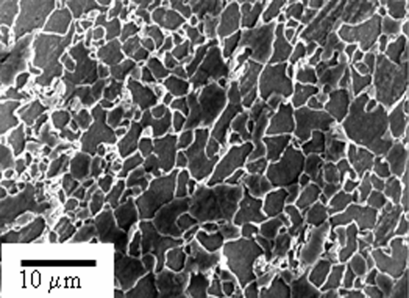 | Figure 2. SEM micrograph of the sample deformed at 800°C showing the ultra-fine ferrite grain structure |
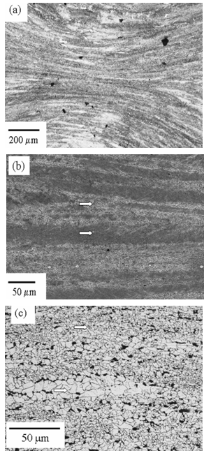 | Figure 3. (a and b) Deformed region of the compression tested sample showing the formation of UFF grains along the prior-γ grain boundaries; (c) After slow cooling, prior-γ grain centre turned into lens-shaped coarse-α grain regions, which were surrounded by the UFF grains formed along the γ-grain-boundary regions. The prior-γ grain-boundary and grain-centre regions are indicated by arrows |
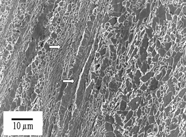 | Figure 4. Ferrite grain size variation observed in the inter-critically deformed (at 700°C) and slowly cooled sample. Coarse-grain raft and fine-grain region is arrowed and the arrows are along the direction of compression of the sample |
4. Conclusions
- Major conclusions derived from the present investigation are summarized below:• Single pass or multi-pass deformation refined the ferrite grain size nearly to the ultra-fine range (~3 μm or below), when heavy deformation (true strain, ε > 0.8) has been applied between Ae3 and Ar1 temperatures.• Fine-scale ferrite grain size variation remains even in the ultra-fine grain structures due to the dynamic γ→α transformation (DSIT) preferentially along the γ grain boundaries, whilst, γ-grain centre regions transform statically.• Different rate of α-nucleation and α-grain growth between γ-grain boundary (high nucleation and stronger impingement) and γ-grain centre may also create a grain size variation after DSIT.• Inter-critical deformation can also create ferrite grain size variation due to the extended dynamic recovery of ferrite grains and static transformation of austenite.
ACKNOWLEDGEMENTS
- Authors acknowledge Department of Science and Technology, New Delhi and Tata Steel, Jamshedpur, for the research funding and I.I.T. Kharagpur, Tata Steel and RDCIS, SAIL for the provision of research facilities.