-
Paper Information
- Next Paper
- Previous Paper
- Paper Submission
-
Journal Information
- About This Journal
- Editorial Board
- Current Issue
- Archive
- Author Guidelines
- Contact Us
International Journal of Metallurgical Engineering
p-ISSN: 2167-700X e-ISSN: 2167-7018
2013; 2(1): 40-46
doi:10.5923/j.ijmee.20130201.06
Thermo-Mechanical Behavior in Steels: Transformation Plasticity
 Abstract
 Reference
 Full-Text PDF
 Full-text HTML
Heung Nam Han1, Yi-Gil Cho2, Hoon-Hwe Cho1, Moon-Jo Kim1, Dong-Wan Kim1, Yang-Hoo Kim1
1Department of Materials Science and Engineering and Center for Iron & Steel Research, RIAM, Seoul National University, Seoul 151-744, Republic of Korea
2Korea Institute of Science and Technology (KIST), Seoul, 136-791, Republic of Korea
Correspondence to: Heung Nam Han, Department of Materials Science and Engineering and Center for Iron & Steel Research, RIAM, Seoul National University, Seoul 151-744, Republic of Korea.
| Email: |  |
Copyright © 2012 Scientific & Academic Publishing. All Rights Reserved.
Permanent deformation that originates from transformation plasticity has favorable aspects for steels with improved strength and ductility. However, it also causes undesirable deformation of products or specimens, leading to their degradation. This article reviews recent investigations of transformation plasticity. A combination of newly suggested models, numerical analyses, and novel experiments has attempted to reveal the mechanism. Since the nature of the transformation plasticity is still unclear, there are significant challenges still to be solved. Fundamental understanding of transformation plasticity will be essential for the development of advanced steels.
Keywords: Steels, Transformation Induced Plasticity (trip), Accelerated Creep, Mechanically Induced Martensite Transformation, Dilatometry, fem
Cite this paper: Heung Nam Han, Yi-Gil Cho, Hoon-Hwe Cho, Moon-Jo Kim, Dong-Wan Kim, Yang-Hoo Kim, Thermo-Mechanical Behavior in Steels: Transformation Plasticity, International Journal of Metallurgical Engineering, Vol. 2 No. 1, 2013, pp. 40-46. doi: 10.5923/j.ijmee.20130201.06.
Article Outline
1. Introduction
- Transformation plasticity has been believed to be a mechanism that causes permanent deformation during phase transformations of polycrystalline materials even under their yield stresses. As usage of the transformation plasticity in the contexts of strength and ductility[1,2], so-called transformation-induced plasticity (TRIP) steels[3], have attracted great interest in the automotive industry. However, sometimes the deformation due to transformation plasticity is undesirable for products or specimens, and that it degrades material qualities. For example, the situations listed below describe degradation in processing or experiments.(a) Hot-rolled coils sometimes contract asymmetrically during steel making/storing processes. Transformation plasticity is believed to be the primary reason[4].(b) Permanent deformations and residual stresses occur in welding processes[5]. Considerable portions of deformation might be caused by transformation plasticity.(c) Dilatation curves that contain the contribution of transformation plastic deformation may cause significant errors in dilatometry[6,7].Since super-plastic like deformation due to transformation plasticity was reported, many researchers have begun to investigate its origin and nature extensively. Many theories and models have been proposed, which have been categorized into two main groups. For diffusive transformation, Greenwood and Johnson[8] derived an analytical solution for transformation plastic deformation on ideally plastic materials. They assumed that plastic deformation occurs in a weaker phase to accommodate external and internal stresses by volume mismatches between two solid phases. This model has been modified, extended and reproduced by other researchers. For example, Leblond et al. demonstrated the interaction between classical plasticity and TRIP[9,10], Taleb and coauthors re-evaluated the Leblond model by providing various experimental grounds[11-13], Fischer et al. quantified the effect of the orientation on the deformation of shape memory alloys[14-16]; Mahnken et al. utilized a unit-cell RVE model to find the mechanical behavior of macroscopic austenite/martensite composite, which combines the effect of classical plasticity and transformation induced plasticity[17]. On the other hand, Magee paid attention to the displacive martensitic transformation by which transformation plastic deformation is also induced[18]. The preference of a specific variant under a certain stress field was adopted to describe the deformation. Based on this theory, several models were proposed with extended or more generalized constitutive relations. Han et al.[1] proposed a nucleation-controlled kinetics based on Olson and Cohen’s approach[3,19] in order to compensate for the disadvantage of kinetics in the strain-induced martensitic transformation[20-23]. Other approaches frequently adopted for the representation of the macroscopic behavior of phase transformed materials are used to introduce the micromechanical or multi-scale modeling techniques[14,24-31]. Recently, Levitas and Ozsoy developed a micromechanical approach by modeling the universal thermodynamic driving force for the interface reorientation to derive the stress- or strain-induced martensite transformation. In the application part of their micromechanical model, various types of representative volumes were built to validate the effect of the athermal threshold, the martensite variants and an interface orientation under three dimensional thermo-mechanical loading [27,28,32].In this article, recent investigations of transformation plasticity, which attempted to reveal its mechanism and nature, are reviewed[33]. These investigations include newly developed theories, numerical approaches, and novel experiments.
2. Representative Theories
2.1. Accelerated Creep Model[34]
- During the diffusive phase transformation, the phase interface migrates through the movement of atoms across the interface. Generally, it can be assumed that the overall atomic flux across the interface will be perpendicular to the interface and that the migrating atoms will rearrange at the nearest atomic site in the transformed phase. However, when an external stress is applied, the migrating atoms will move to positions where they can release the applied stress field, and this can give rise to an atomic flux along the phase interface. This phenomenon may be similar to the mechanism of Coble creep.The model of Greenwood and Johnson has been modified to include the temperature-dependence of the strain rate caused by the transformation plasticity[35,36]. These models could simulate the thermally activated behavior of the transformation plasticity in a relatively high temperature range. All of these models were based on the volume mismatch between the two phases and the creep deformation of the weaker phase during the phase transformation under externally applied stress. Recently, however, several sets of experimental results have been reported, which were difficult to explain by the Greenwood and Johnson’s consideration. One of these is that an externally applied stress, even much lower than the yield stress of the material, induces considerable permanent strain during the recrystallization and growth in extra low-carbon steels[37]. Since there is little volume mismatch between the unrecrystallized and recrystallized region, the evolution of permanent strain during recrystallization is difficult to interpret by the volume mismatch induced internal stress model. Besides, it was found that the deviation angle from the Kurdjumov-Sachs (KS) orientation relationship considerably increased with the uniaxially applied stress during the austenite-to-ferrite transformation of steel[38,39], which implies that the sliding of the migrating transformation interface possibly occurs when the external stress is applied during phase transformation. From the above experimental observations, the transformation plasticity behavior of steel during the phase transformation under externally applied stress is modeled on the basis of a migrating interface diffusion mechanism, which is described as an accelerated Coble creep. The mathematical form of the model can be expressed as follows:
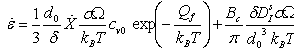 | (1) |
2.2. Martensitic Transformation[1]
- A one-dimensional model for the kinetics of strain-induced martensitic transformation was developed by Olson and Cohen[19]. Stringfellow et al. derived a constitutive model for the kinetics of mechanically-induced martensitic transformation that considered the external stress state in terms of the hydrostatic pressure and the equivalent shear stress[20].
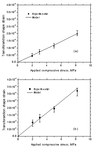 | Figure 1. Transformation shape strain after transformation as a function of applied stress during (a) cooling and (b) heating by 2 °C/sec[34] |
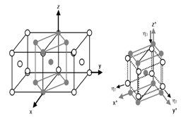 | Figure 2. Lattice correspondence between FCC and BCT and the Bain deformation accompanying with the transformation[1] |
3. Representative Researches
3.1. Dilatometric non-isotropy[6]
- Generally, it is known that non-isotropic volume changes in dilatometry have also been observed during the phase transformation, even in steel with an isotropic microstructure[44]. The contribution of the non-isotropic volume change to the dilatation data was recently quantified and this change was incorporated into a dilatometric analysis model[44].
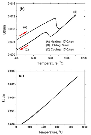 | Figure 3. Measured dilatation curves for (a) ultra-low carbon steel (steel ULC) during a thermal cycle with 1 K/s and (b) low carbon steel (steel LC) during a thermal cycle with 10 K/s[6] |
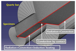 | Figure 4. FE meshes and boundary conditions for heat transfer in the dilatometric system[6] |
 | (2) |
 and
and  are the elastic stiffness tensor and the elastic strain increment, respectively.
  ,
,  and
and  are the volumetric strain increment due to the phase transformation and temperature change, the transformation plasticity strain increment associated with the phase transformation and the plastic strain increment, respectively. In order to estimate precisely the interfacial heat transfer rate on the surface of the dilatometric specimen, including the induction heating, an inverse heat transfer technique was used. The dilatometric behaviors of both conventional low carbon and ultra-low carbon steels were simulated by using the FE model. To validate the suggested FE model, the measurement of the dilatation curves was carried out for these low carbon and ultra-low carbon steels and we compared the simulation results with the experimental data (Fig. 5). From the simulation results, the origin of the non-isotropic dilatation in the specimens was discussed.The transformation plasticity was caused by the small amount of stress that naturally developed in the specimen during the dilatometric experiment. In the conventional low carbon steel, the stress in the specimen formed mainly due to the very small external force supplied to support it during the dilatometric experiment. As regards the ultra-low carbon steel, whose phase transformation occurs within an extraordinarily narrow temperature range, the inhomogeneous phase transformation due to the thermal gradient along the radial direction in the specimen was mainly responsible for the stress field in the specimen during the dilatometric experiment.
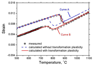 | Figure 5. Comparison between calculated (lines) and measured (symbols) dilatation curves. Curves A and B represent the dilatometric curve calculated without and with considering transformation plasticity, respectively[6] |
3.2. Microstructurally Banded Steel[7]
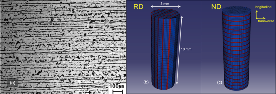 | Figure 6. (a) Microstructure of the hot-rolled steel. (b and c) Finite-element mesh for the dilatometric specimens: (b) RD specimen showing the longitudinal direction parallel to the rolling direction, and (c) ND specimen showing the longitudinal direction perpendicular to the rolling direction[7] |
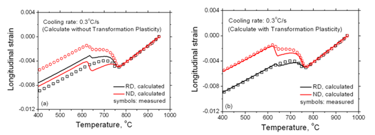 | Figure 7. compares the calculated and measured dilatation curves of the RD and ND (indicated in the figure) specimens[7] |
3.3. Asymmetric Contraction of Coil[4]
- A hot-rolled steel strip is generally stocked in the form of a hollow cylindrical coil after the hot rolling process. The hot coil is cooled from 500-700 °C to room temperature over a 4-5-day period under natural air cooling conditions[49,50]. In most hot strip rolling processes, the phase transformation of the steel is finished on the run-out table (ROT) before coiling[51], and the hot coil is normally cooled down but maintained in a cylindrical shape[52]. However, asymmetric contraction occurs in an actual mill during cooling after the coiling of hot-rolled steel, which has significantly high hardenability due to its high content of carbon or other alloying elements and shows incomplete phase transformation prior to coiling, as can be seen in Fig. 8. This asymmetric contraction behavior is closely related to the phase transformation that occurs after coiling, and cannot be described by conventional creep behavior. This shape change in the hot coil causes acute problems in industrial applications, such as serious scratching on the strip surface during uncoiling. The constitutive equation for transformation plasticity was incorporated into a general purpose implicit FE program. In addition to the thermo-elasto-plastic constitutive equations, the phase transformation kinetics was characterized by a JMAK type equation.
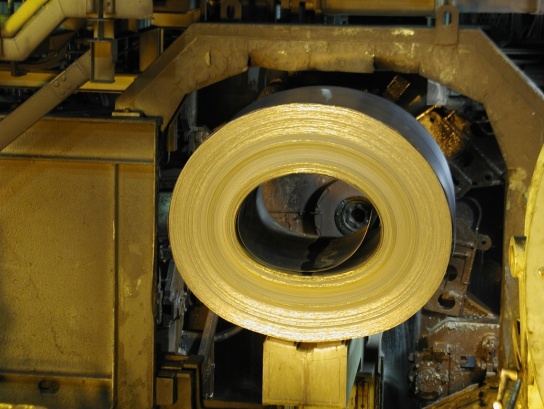 | Figure 8. An example of asymmetric contraction of hot coil after coiling[4] |
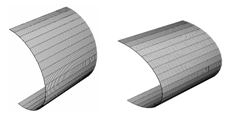 | Figure 9. Deformed shapes of the hot coil after cooling to room temperature, which are calculated by one layer FE modeling without (a) and with (b) the consideration of the transformation plasticity, respectively. Displacement was enlarged by 1.5 times for both cases[4] |
4. Challenges and Further Studies
- Although this article starts by looking at the undesirable aspects of transformation plasticity, the primary concern is not the degradation by itself, but rather its mechanism and nature. Fundamental understanding of transformation plasticity will be a key to future research. Many previously published studies have attempted to take advantage of transformation plasticity. The representative materials are TRIP aided steels[3], which have engineering importance in the automotive industry. Twinning-induced plastic deformation is also attracting considerable interest for the possibility that it might lead to remarkable improvement in both strength and ductility. However, there is still a lack of fundamental investigations, possibly due to obstacles that derive from the requirements of nano-scale engineering. Transformation plasticity can hardly be observed or measured on the nano/micro-scale. Despite recent study that have adopted the phase field model (PFM) into the FE model in order to consider micro-scaled transformation plasticity[53], the mechanism and nature of transformation plasticity are not clear. Obviously, the requirements to understanding this uncertainty will increase, and many opportunities will arise. Future works will have to be carried out as close collaborations between nano/micro-scale experiments and observations, along with numerical analysis.