-
Paper Information
- Next Paper
- Previous Paper
- Paper Submission
-
Journal Information
- About This Journal
- Editorial Board
- Current Issue
- Archive
- Author Guidelines
- Contact Us
International Journal of Metallurgical Engineering
p-ISSN: 2167-700X e-ISSN: 2167-7018
2013; 2(1): 10-17
doi:10.5923/j.ijmee.20130201.02
Microstructural Simulations via Thermal Processing of Roll Bonded Steel Laminates
 Abstract
 Reference
 Full-Text PDF
 Full-text HTML
David K. Matlock, Ralph J. Johnson, Emmanuel De Moor, John G. Speer
Advanced Steel Processing and Products Research Center , Colorado School of Mines, Golden, Cousa, 80401
Correspondence to: David K. Matlock, Advanced Steel Processing and Products Research Center , Colorado School of Mines, Golden, Cousa, 80401.
| Email: |  |
Copyright © 2012 Scientific & Academic Publishing. All Rights Reserved.
Laboratory processed laminated composites, designed to simulate compositional gradients present in cast and hot rolled industrial microstructures, wereused to assess microstructural evolution during heat treating and the effects of specific microstructural variables on mechanical propertiesin steels. In this paper, two microstructural systems are presented to illustrate the broad applicability of the simulation technique. In one example, artificial compositional segregation of Mn was introduced to simulate microstructural banding observed in most industrial cast and hot rolled steels. Laminates were produced from two nominally 0.4 wtpct C steels with either 0.82 or 1.83 wtpctMn. The effects of composition band width and heat treatment, designed to alter the sharpness of the Mn gradients between layers, on microstructures andtensile properties are presented. In a second example, multiphase microstructures characteristic of the next generation advanced high strength sheet steels (AHSS) were simulated by roll bonding alternating layers of a steel with 2 wtpctMn and another steel with 18 wtpctMn. The resulting mechanical properties correlate to predictions of a composite model when sufficient interfacial strength was achieved to prevent tunnel crack formation.
Keywords: Laminated Composites, AHSS, Simulated Microstructures, Banding
Cite this paper: David K. Matlock, Ralph J. Johnson, Emmanuel De Moor, John G. Speer, Microstructural Simulations via Thermal Processing of Roll Bonded Steel Laminates, International Journal of Metallurgical Engineering, Vol. 2 No. 1, 2013, pp. 10-17. doi: 10.5923/j.ijmee.20130201.02.
Article Outline
1. Introduction
- Multi-scale modeling analyses which lead to property predictions of steel microstructures with multiple constituents (e.g. ferrite, bainite, martensite, austenite, carbide precipitates, inclusions, etc.) have become important components of research programs designed to identify, and eventually produce, new steels with enhanced properties for critical applications[1-4]. Essential to all models, are expressions that describe the deformation characteristics (yielding, strain hardening, etc.) of the individual constituents. The various modeling approaches differ with respect to the method used to integrate properties of individual phases and constituents and to incorporate interfacial properties and interactions between constituents. While most models concentrate on deformation behavior, some incorporate critical fracture criteria[5].In steels with stable microstructures (i.e. without deformation induced transformation of austenite to martensite) interrelationships between microstructural constituents, strength, strain hardening, and ductility in tension are considered in terms of equations that relate operable strengthening mechanisms to strain-dependent expressions[1,2] and take the form shown in Eq. 1
 | (1) |
2. Laboratory Production of Simulated Microstructures
- A roll bonding procedure was developedto processa variety of alloy combinations on a laboratory rolling mill with 133 mm diameter by 203 mm face work rolls[10-13]. Typically two component materials were evaluated; the procedure could be easily modified toincorporate more than two primary constituents. Prior to fabrication of the final roll bonded compact, each experimental material was hot rolled, and in some cases cold rolled, to a final thickness of nominally 0.5 mm. To facilitate bonding and to eliminate the presence of undesirable inclusions at bond interfaces, prior to roll bonding, all sheet surfaces were pickled to remove oxides and mechanically cleaned with a commercial abrasive cloth.Figure 1 shows the procedure for fabricating the roll bonded laminated compacts. For each two-component material of interest,alternating sheet layers, nominally 0.5 mm thick with widths and lengths of 90 and 125 mm, respectively, were encased in a welded stainless steel box. Figure 2 shows an example welded compact that included a vacuum attachment tube welded to one end. During TIG welding the layered stack and formed stainless steel box parts were compressed in a hydraulic press to minimize space between layers. The relative volume fractions of each constituent were varied by controlling sheet thickness.The welded boxes were connected to an active vacuum system and preheated to the desired rolling temperature selected based on the specific alloys of interest. The compacts were hot rolled to the final sheet thicknesses selected to produce specific band thicknesses based on the initial sheet thicknesses of the individual layers. To ensure bonding, the initial pass was the maximum achievable on the laboratory rolling mill. Typically primary bonding occurred in the first one or two passes and after three to four passes the vacuum tube separated from the compact. Subsequent rolling was completed in air, and intermediate reheating was used as necessary.
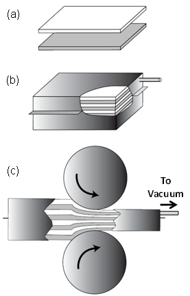 | Figure 1. Schematic of production steps for roll bonded laminated composites (a) alternately stacked sheets; (b) sheet compacts sealed in stainless steel boxes; and (c) boxes attached to an active vacuum system and hot rolled[13] |
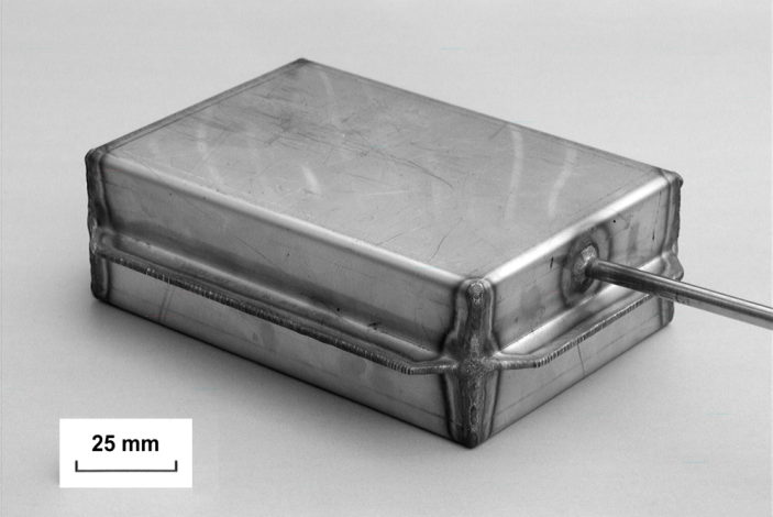 | Figure 2. Example TIG welded stainless steel box prior to hot rolling[12] |
3. Review of Model Systems
- Roll bonded laminate composites have been used to model properties in steels and other alloys with multi-component microstructures and have been used to produce new materials with enhanced properties[14,15]. Selected example systems and fundamental principles that have been considered include the following: fabrication and properties of Damascus steels[14]; fabrication and fracture assessment of high energy absorbing materials[16,17]; alloy homogenization during annealing with results applicable to cored castings and weldmentsand the effects of cored microstructures on the high temperature mechanical properties of weldments[18,19]; homogenization of thin thermally-sprayed coatings on substrates at elevated temperatures[20]; neutron diffraction studies of stress partitioning during deformation of multi-phase steels[21]; fundamental analyses of the Kirkendall effect and diffusion-induced porosity formation[22]; and banding in steels[11-13].In the latter studies, manganese banding and its potential effects on phase transformations and heat treat responses of steels were considered and selected results are presented here.Banded 0.4 C steels with alternating equal-thickness layers of 0.8 or 1.8 Mn (wtpct) were processed with band widths between 10 and 320 µm to simulate banding observed in rolled and/or forged SAE 5140 steel and used to evaluate the effects of band width on phase transformations and tensile properties[11-13]. Results assessed the effects of heating and of cooling rates (83°C/s to 8.3x10⁻³°C/s) on phase transformations and layer interactions critical to the development of the final microstructures. To illustrate the importance of banding on layer-dependent properties, Fig. 3 shows engineering stress-strain curves for samples with various band widths cooled at 0.6°C/s (Fig. 3a) and 1.7x10⁻²°C/s (Fig. 3b) from 850°C[11]. The tensile properties for samples cooled at 0.6°C/s depend sensitively on band width, which, as discussed below, reflects the development of diffusion controlled interfacial layers of constant thickness. In contrast, the properties for samples cooled at a much lower rate (Fig. 3b) are essentially independent of band thickness.The cooling-rate dependence of the effects of layer thickness were clarified via light optical microstructure analyses[11,12] and selected micrographs for samples cooled at 0.6°C /s from 850°C are shown in Figs. 4a and 4b for 160 and 20 µm samples, respectively. At this intermediate cooling rate, a 20 µm interfacial band of pearlite[12] developed in addition to the ferrite pearlite band in the low Mn layer and a high strength bainitic band in the high Mn layer. In contrast, the pearlitic interface band is shown to completely encompass the high Mn layer in the 20 µm thick banded condition. Thus, with an increase in layer thickness, the volume fraction of the high strength bainitic band increases with band width leading to the strength effects shown in Fig. 3a. At the lower cooling rate (1.7x10⁻²°C/s), alternating ferrite-pearlite bands developed and the tensile properties were independent of band width (Fig. 3b). Related studies have shown that as a result of composition gradients in banded steels, displacements associated with the differential transformation response between layers and response to non-uniform heating, as imposed during induction hardening, depend on orientation with respect to the banded structure[12,23].
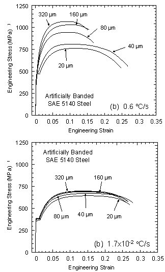 | Figure 3. Room temperature engineering stress strain curves for artificially banded SAE 5140 steel processed with band widths between 20 and 320 µm and cooled at (a) 0.6 °C/s and (b) 1.7x10⁻²°C/s[11] |
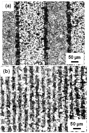 | Figure 4. Light optical micrographs of artificially banded SAE 5140 steel cooled at 0.6 °C/s with band widths of (a) 160 µm and (b) 20 µm (2 pctnital etch)[11] |
4. Third Generation Advanced High Strength Steels (Ahss)
- Recently there has been considerable interest to develop and evaluate models to predict properties characteristic of the new class of sheet steels referred to as the “Third Generation of Advanced High Strength Steels (AHSS)”[24,25]. One approach, based on the application of a multi-component iso-strain composite model[1,2,26] to multi-phase steels, has provided insight into microstructural constituents that will be required for Third Generation AHSS products. Predictions of tensile instability (i.e. combinations of uniform elongation and ultimate tensile strength) based on assumed mixtures of ferrite + martensite or (stable) austenite + martensite are overlaid in Fig. 5 on a property map developed by AISI[24]. The property comparisons show that mixtures of ferrite and higher strength martensite (or “ultra-fine” ferrite) are attractive and represent a broad range of ferrite-based steels while austenite + martensite combinations generate properties well within the targeted Third Generation property band.
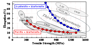 | Figure 5. Tensile elongation/strength combinations for various steel families and 3rd Generation AHSS overlaid with property combinations predicted for various combinations of martensite and ferrite or (stable) austenite[1] |
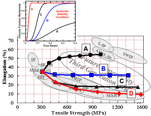 | Figure 6. Tensile ductility/strength combinations for mixtures of martensite and metastable austenite, with austenite mechanical stability varying as shown in inset[2] |
| |||||||||||||||||||||||||||
|
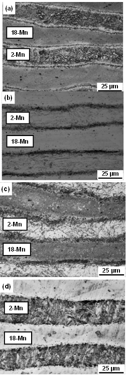 | Figure 7. Light optical micrographs of the 2-Mn/18-Mn laminate composite in the (a) as hot rolled condition or after annealing at (b) 685°C, (c) 730°C, and (d) 790°C (etched with 10 pctnital) |
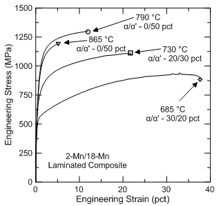 | Figure 8. Representative engineering stress-strain curves for the 2-Mn/18-Mn laminate composite after quenching from the indicated temperatures |
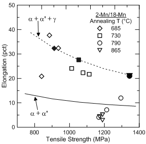 | Figure 9. A comparison of the predictions (closed symbols) for the 2-Mn/18-Mn laminate composite model analysis with experimentally measured tensile properties (open symbols) |
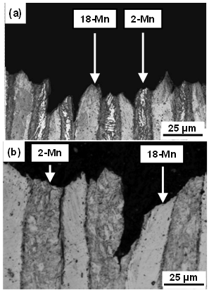 | Figure 10. Light optical micrographs of fractured tensile samples of 2-Mn/18-Mn laminatequenched from (a) 730°C and (b) 790°C |
5. Summary
- A laboratory technique to produce simulated complex microstructures with roll bonded laminated composites has been shown to provide a unique method for evaluating the effects of heat treating on microstructures and properties of multi-phase steel alloys. Insight provided by the simple composite model analysis which successfully predicted tensile properties in a microstructural system designed to simulate potential Third Generation AHSS products provides guidance for the development of future AHSS microstructures and properties. The results also illustrate the potential importance of interdiffusion between layers on microstructure development.
ACKNOWLEDGEMENTS
- The authors gratefully acknowledge the support of the National Science Foundation for support under award CMMI-0729114 and the sponsors of the Advanced Steel Processing and ProductsResearchCenter, an industry/university cooperative research center at the Colorado School of Mines.