-
Paper Information
- Next Paper
- Previous Paper
- Paper Submission
-
Journal Information
- About This Journal
- Editorial Board
- Current Issue
- Archive
- Author Guidelines
- Contact Us
International Journal of Metallurgical Engineering
p-ISSN: 2167-700X e-ISSN: 2167-7018
2012; 1(6): 117-121
doi: 10.5923/j.ijmee.20120106.04
Selection of Proper Refractory Materials for Energy Saving in Aluminium Melting and Holding Furnaces
 Abstract
 Reference
 Full-Text PDF
 Full-Text HTML
R. N. Nandy, R. K. Jogai
Refractory Maintenance Department, National Aluminium Company Limited, Smelter Plant, Angul, 759145, India
Correspondence to: R. N. Nandy, Refractory Maintenance Department, National Aluminium Company Limited, Smelter Plant, Angul, 759145, India.
| Email: |  |
Copyright © 2012 Scientific & Academic Publishing. All Rights Reserved.
Refractory lining of an aluminum melting and holding furnace are engineered with a primary design objective to keep the furnace condition stable throughout the life of the furnace. In consideration of energy saving, ideally all the heat added to the furnace should be used to heat the load or stock but in practice, a lot of heat is lost in several ways. Energy input to metal output depends on factors apart from energy losses through the furnace wall i.e. through flue gas, moisture in fuel, hydrogen in fuel, opening of furnace door. These heat loses can be differentiate as, wall losses at steady state operating condition and heat storage loss during transient condition. Practically apart from flue gas loss, majority of the heat loss took place during the transient condition. Heat loss through refractory wall during steady state condition depends on thermal conductivity, resistance against thermo chemical attack from aggressive liquid aluminium and its alloy and resistance against mechanical wear. High porosity, low thermal conductive materials due to lower strength and lower resistance towards chemical attack reduce life of the furnace and in contrast high density refractory materials needs multilayer backup to save potential energy loss through the refractory wall. This paper discusses the proper selection criteria and best suitable solution of refractory materials for aluminium Melting & Holding furnace which can contribute potential energy saving.
Keywords: Melting Holding Furnace, Refractory Corrosion, Energy Saving
Cite this paper: R. N. Nandy, R. K. Jogai, "Selection of Proper Refractory Materials for Energy Saving in Aluminium Melting and Holding Furnaces", International Journal of Metallurgical Engineering, Vol. 1 No. 6, 2012, pp. 117-121. doi: 10.5923/j.ijmee.20120106.04.
Article Outline
1. Introduction
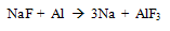
- There are many factors which limit the uses of refractory such as service environment, service temperature, mechanical degradation and the ability to install or repair of the refractory materials in a cost effective manner. These limitations are related to the energy efficiency of the processes, as degradation of refractory reduces the thickness of walls, cause heat loss through the walls and increases exponentially. This condition requires cooling of the furnaces for maintenance and again reheating for further uses which causes huge loss of energy and production time. Refractories for aluminum melting and holding furnaces must withstand mechanical abuse from charging, from thermal shock due to cyclic heating and from complex forces on the refractories when molten metal penetrates their surface. Penetration can destroy the furnace.In metal melting furnaces, wear of the refractory lining is not uniform in nature; it is severe in specific areas where most corrosive condition exists. In melting furnaces the most severe condition occurs at the metal lines where solid refractory comes in contact with liquid metal and gaseous environment above the liquid metals.In case of aluminum melting and holding furnaces corundum deposit as surface agglomerates, leads to spalling of refractory wall due to alumina surface concretion and porosity increases in the refractory structure for internal corundum growth.Below the metal lines the degraded refractory reduces the thickness of the wall and floor. This condition reduces the thermal efficiency of the furnaces leading to high heat loss and can lead to failure of thermal balance of the furnaces.
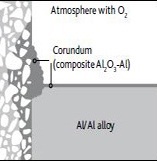 | Figure 1. Corrosion of refractories in contact with molten aluminium |
2. Energy Losses in Aluminum Melting Furnaces
- The heat loses can be differentiate as, wall losses at steady state operating condition and heat storage loss during transient condition. Practically apart from flue gas loss, majority of the heat loss took place during the transient condition due to the opening loses and depends on type of furnace and operating condition which is sometimes unavoidable due to process requirement. The majority of the heat loss i.e. around 40% of heat input is flue gas loss and only an estimated 10% of available heat is lost through the refractory wall during steady state operating conditions.[1]To reduce the energy loss through refractory wall in steady state condition refractory wall should have low thermal conductivity, resistance against thermo-chemical attack from aluminum and its alloying elements and resistance against mechanical abuses.The potential for energy savings through the refractory lining in aluminum furnaces will now be discussed, and in particular, how refractory materials can contribute significantly to overall energy savings.
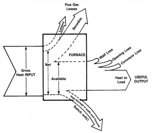 | Figure 2. Sankey diagram: Different types of energy losses in aluminum melting furnace |
3. Refractory Lining in Transient Phase
- The furnace refractory lining is often exposed to thermal shock during skimming, cleaning, fluxing and charging. The severity of these forces increases sharply with increasing furnace size and varies widely with operation practice. Mechanical shock and abrasion are severe where large quantities of cold scrap are directly charged with solid materials through the main door or through doors on one side wall or are charged into a well containing molten aluminum. All this practice leads to massive energy losses and as a consequence, stresses generates in the lining which can cause damage of the refractory lining and eventually a reduction of the furnace refractory life. When a furnace needs to shut down, cooling and shrinking of the lining create a gap between the hot face and back-up insulation, which could cause a lining failure during restart. Most of the lining shrinkage is caused by the contraction of the aluminum in cracks of the lining as aluminum has shrinkage greater than 6%[2]. In the lining apart from hot metal contact area sills, door jambs and furnace door are the most vulnerable area to thermal shock. The energy efficient high porosity light weight insulating refractory materials cannot be used in the hot face lining due to the lower chemical and mechanical resistance, less energy efficient, high thermal conductive, dense refractory materials must have to be used which requires a multi layer refractory lining.Degradation of refractory lining in the refractory hot face leads to the freeze plane changes towards the insulating material which ultimately causes aluminum infiltrations into the porous insulating lining through the hot face layer cracks. To maintain stable furnace conditions and to save energy, it is essential to install hot face refractory materials which are resistant to contacts with the liquid metal and atmosphere. The refractory lining of the furnace under transient conditions should have excellent thermal shock properties i.e volume stable, high thermal conductivity, low thermal expansion and also to maximize energy efficiency material should have low heat capacity in order to reduce storage heat loss.
4. Corrosion and Metal Penetration
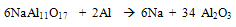
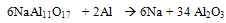
- The main problem associated with aluminum melting and holding furnaces is the corrosiveness of molten aluminum and its alloying elements. The corrosion of alumino-silicate refractories by molten aluminum, generally leads to the formation of an alumina deposit on the refractory. The presence of alkalies and under a reducing atmosphere increases the corrosion also metal contamination in molten aluminium confinement depends on the characteristics of the refractory i.e their chemical and mineralogical composition, types of binder, and permeability. The susceptibility of the refractory to the corrosion in the furnaces depends on these characteristics. Such corrosion promotes the formation of inclusion in the molten metal, which can also originate from its direct oxidation at the metal line. Increase in permeability favors the corrosion by molten metal and permits the gas migration like oxygen and water vapors.The products of oxidation of molten aluminium alloy are a function of the alloy composition. At operating condition of aluminium melting furnace, the presence of Mg favours the formation of spinel (MgAl2O4). At less than 3 wt %, Al2O3 is the most stable oxide in these conditions, while at more than 18 % it is MgO.[3] These oxides may result from the action of oxygen gas. Also the alkali content (less than 2%) in the refractory may be present as amorphous phases such as sodium silicate or crystalline compound such as beta alumina (NaAl11O17). These phases are highly prone to reduction by aluminum which releases the alkali to molten aluminum.
 | (1) |
 | (2) |
 | (3) |
4.1. Mechanism of Corundum Build-Up
- Along the operation of furnaces, the corrosion of refractories by molten aluminum is generally accompanied by the formation of a surface deposit of corundum on the lining, especially at the metal line, where the effect of atmosphere and alkaline vapors is at maximum. Microscopic observations of the corundum layer shows that the corundum layer looks like a composite material with fine grains of corundum surrounded by an interconnected metallic network [5]. The metallic aluminium network provides the channels to supply fresh aluminum to the reaction interface during the corrosion process. The deposited corundum layer is difficult to remove during furnace cleaning due to its high adherence to the lining. There are two specific mechanisms of corundum formation based on location within the furnace.
4.1.1. Internal Corundum Growth
- Internal corundum formation occurs due to reduction process of refractory components by aluminum metal and alloying elements. Below the liquid metal line refractory surface is the main area for internal corundum growth. The reaction takes place in the pore system of the refractory material and leads to a decomposition of the matrix. When the furnaces lined with alumino-silicate refractories, aluminium gradually penetrate into the refractory and molten aluminum reduces the refractory oxides such as silica, thereby forming corundum.The reactions can be described as:[6]
 | (4) |
 | (5) |
4.1.2. External Corundum Growth
- The second mechanism of corundum formation is referred to as "external corundum growth. External corundum growth is a function of oxygen partial pressure in the furnace in the presence of aluminum and alloying elements like silicon and magnesium. At the liquid metal line, solid refractory, liquid aluminum and atmospheric oxygen are all in contact at one point and known as the triple point. The corundum build-up occurs at the metal line, of the furnace at the interface of the atmosphere, aluminum bath, and the refractory lining. Availability of oxygen leads to a more severe corundum formation and the damage is extended to some height above the metal line. This zone of excessive corrosion is commonly known as the "bellyband area". Molten aluminum penetrates into the refractory, by capillary action and oxidizes by reaction with atmospheric oxygen leading to the formation of large corundum mushrooms that adhere to the refractory lining. The effective furnace volume shrinks due to this process and reduces the energy input to metal output ratio. The alloying elements like Mg speed up the corrosion process and can reduce the refractory oxides more aggressively than aluminum.
 | (6) |
 | Figure 3. Corundum formation in a side wall of aluminum melting furnace |
5. Refractory Selection Considerations
- From the above discussion it is understood the refractory materials for melting & holding furnace should have volume stable, accuracy in shape & dimension, good mechanical strength and resistance to abrasion, oxidation and reduction. Practically no refractory materials combine all this properties in the best possible way. Generally there are two main practical ways to avoiding corrosion of refractory i.e. Addition of additive in refractory material during its manufacturing and protective coating on refractory wall.Alumina silicate refractories having less silica content or higher alumina silica ratio normally exhibit a superior resistance to aluminium attack. For aluminum metal to attack a refractory lining, two conditions must be fulfilled. First, the refractory material must be reducible by molten aluminum metal and second, the two reacting species must be in contact with each other.The fact is that refractory materials such as silica will be reduced by molten aluminum alloy to form corundum. In order to minimize contact between molten aluminum and the refractory, "anti-wetting" additives have been added to refractory mixes. The primary role of such additives is to reduce the wettability of the refractory by molten aluminum. This will minimize the contact between the two species and result in improved corrosion resistance. Aluminum fluoride, calcium fluoride and barium sulfate have been generally used as anti- wetting additives.In conventional cement bonded monolithic materials, additives like BaSO4, CaF2 or AlF2 can temporarily prevent the refractory lining from penetration by aluminum metal and alloying agents. However, these additives possess limited temperature stability and tend to react with certain fluxes even at low temperatures thereby losing their effectiveness. The use of a non-wetting additive is not always a sufficient solution to improve the corrosion resistance of refractories against molten aluminum. Once in contact with liquid aluminum, the coarse refractory aggregates, which do not benefit from the non-wetting additives in the matrix, may be corroded. In some cases, the corrosion of aggregates promotes corrosion in the surrounding matrix, even in the presence of a non-wetting agent. In general phosphate bonded materials show excellent resistance to aluminium metal penetration and corundum growth. The phosphate bond generally provides a lower modulus of elasticity compared to more brittle conventional cement and ceramic bonded materials. The flexible bonding mechanism results in higher impact resistance. Phosphate bonded bricks with low alkali content possess high hot strengths at elevated temperatures which can significantly increase their performance against mechanical abuse and chemical attack. These combined properties are very useful in the area where the mechanical and chemical abuse is more. The characteristics are important in hot wall applications of side well charging furnaces where arch and metal line areas are exposed to mechanical wear in combination with chemical attack.During manufacturing Phosphate bonded bricks are either fired above 1000°C or heat treated between 150°C and 800°C. In low temperatures fired materials addition of non-wetting additives can be done which is otherwise decompose at higher temperature above 1000°C.[9] Also Lower firing temperatures creates smaller pore sizes and improved non-wetting properties, which ultimately leads to higher penetration resistance against alkali. But at lower firing temperatures below 600°C modulus of elasticity is less due to incomplete conversion of phosphate phases.Both bricks and monolithic materials are used in furnaces and both have advantages over each other. Since the bricks are pre-fired materials, the structural properties are defined before use. 85 % phosphate bonded bricks are the most volume stable and have excellent thermal shock resistance. For this reason in severe applications areas such as impact zones of floors, ramps, and lower side walls, phosphate bonded bricks are still a preferred solution. But in bricks lining the joints of a brick lining is the weakest link metal infiltration, mineral transformations and corundum growth in the joints are frequent problems leading to uncontrolled expansions and bursting of bricks. According to Schacht the modulus of elasticity in the mortar joints is significantly softer than the brick modulus of elasticity, so on thermo-mechanical perspective the mortar joint has a deep influence on the total structural behavior of the lining system [10].In the case of monolithic lining, it shrinks during furnace operation because it does not receive uniform thermal treatment throughout the lining thickness. In some cases shrinkage can compensate the thermal expansion but result a significantly different thermo-mechanical behavior compared to brick linings. In larger monolithic applications, some crack initiation and development is obvious due to the stresses along the thermal gradient in the lining from the shrinkage or expansion. But the advantage of monolithic materials is the absence of larger joints in the structure which makes the lining less vulnerable to metal penetration and can be used by every installation method including casting, gunning, patching and ramming. However, monolithic materials at operating temperature are not in equilibrium with regard to volume stability. Therefore monolithic materials are more susceptible to chemical attack in the environment of aluminum furnaces. Phosphate bonded monolithic Refractories, used in the aluminum industry, are based on liquid phosphate bonded two component binders, dry phosphate salt based systems mixed with water, or plastic Refractories containing a mono-aluminium phosphate binder. The weakness of all these materials is their relatively lower hot strengths and lower high temperature wear resistance compared to phosphate bonded bricks. The problems is that lower hot properties of acidic monolithic phosphate bonded materials due to relatively high liquid content necessary for proper placement. Phosphate binder systems are acidic and therefore dispersants, the water content of phosphate bonded materials are more. As a result, such linings have relatively higher porosity compared to phosphate bonded bricks.It is also possible to make refectories resistant to the molten metal by applying protective coatings by filling the open porosity. It also makes the surface homogeneous and thus minimizing the abrasion and slag erosion. But the coating has a limited durability and needs to be re-impregnated periodically.
6. Summary
- The furnace life and energy efficiency of a furnace depends on the proper selection of refractory materials and its behavior in the furnace environment. The properties and quality of the refractory determine the extent of heat loss during steady state condition and storage heat loss during transient condition. The stoppage of furnace operation caused by refractory failure due to corrosion and mechanical wear leads to major impact on energy saving. The reduction in downtime, due to refractory failure, increases the energy saving and it can be achieved by using phosphate bonded refractory materials. A multi-layer lining with optimized performance of layers with the service environment and proper installation improves the energy efficiency of a furnace.