-
Paper Information
- Previous Paper
- Paper Submission
-
Journal Information
- About This Journal
- Editorial Board
- Current Issue
- Archive
- Author Guidelines
- Contact Us
International Journal of Metallurgical Engineering
p-ISSN: 2167-700X e-ISSN: 2167-7018
2012; 1(4): 66-71
doi: 10.5923/j.ijmee.20120104.04
Effect of Retained Austenite Characteristics on Deep Drawability of TRIP-aided Steel Sheet
 Abstract
 Reference
 Full-Text PDF
 Full-Text HTML
Houman Asmari , Esmaeil Emadoddin , Ali Habibolahzade
Faculty of Materials and Metallurgy Engineering, Semnan University, 35131-19111, Semnan, Iran
Correspondence to: Esmaeil Emadoddin , Faculty of Materials and Metallurgy Engineering, Semnan University, 35131-19111, Semnan, Iran.
| Email: |  |
Copyright © 2012 Scientific & Academic Publishing. All Rights Reserved.
Microstructure of TRIP-aided steel sheets has been recently attracted much interests in improving their formability through different forming processes. Their performance can be successfully controlled by designing an optimum balance in the volume fractions of ferrite, bainite and retained austenite. The retained austenite is considered as the main key to achieving the desired final properties. Against this background, the effects of retained austenite characteristics, such as volume fraction, carbon concentration, size and shape, on the behavior of TRIP steels have been studied. In present study, deep drawability of cold rolled TRIP-aided steel sheets has been evaluated using swift cup test. The steel sheets had two different matrices; Polygonal Ferrite (PF) and Bainitic-Ferrite (BF), and different retained austenite characteristics (volume fraction, morphology and carbon content). Deep drawability of sheets was evaluated and compared in term of limiting drawing ratio (LRD). The results revealed that steels with PF matrix provide better deep drawability due to their higher volume fraction of retained austenite, better stability of retained austenite against deformation and higher difference between hardness of matrix and strain-induced martensite.
Keywords: TRIP Steel, Cold Rolled Sheet, Retained Austenite, Deep Drawability, Polygonal Ferrite Matrix, Bainitic-Ferrite Matrix
Cite this paper: Houman Asmari , Esmaeil Emadoddin , Ali Habibolahzade , "Effect of Retained Austenite Characteristics on Deep Drawability of TRIP-aided Steel Sheet", International Journal of Metallurgical Engineering, Vol. 1 No. 4, 2012, pp. 66-71. doi: 10.5923/j.ijmee.20120104.04.
Article Outline
1. Introduction
- Demands for low-alloyed TRIP-aided cold rolled steel sheets have recently increased in automotive industry due to their high strength and good formability[1-3]. Many experimental studies have been conducted to evaluate stretch formability[4, 5] and stretch flangeability[6, 7] of TRIP-aided steels, while experimental studies on their deep drawability are restricted to Nagasaka’s works[8-10]. Researches indicate that stretch formability of TRIP-aided steel sheets is in direct relation with initial volume fraction of retained austenite and its stability against deformation[5], while stretch flangeability of TRIP-aided steel sheets relates to bainitic matrix[6].Nagasaka et al.[9, 10] have studied the effect of retained austenite morphology and its stability during deep drawability of TRIP-aided steel sheets with ferritic matrix. They concluded that deep drawability of these sheets is affected by volume fraction of retained austenite rather than its morphology and stability. Retained austenite is an important microstructural constituent of TRIP steels. The volume fraction, distribution and transformation characteristics of the retained austenite directly affect the TRIP behaviour. The optimum amount of retained austenite with accurately tuned transformation characteristics (i.e. control of its stability) is of crucial importance for the forming behaviour of the steel[2, 3, 11]. In order to obtain maximum benefit from the TRIP effect, processing conditions such as temperature, strain rate, strain path and stress state during the forming operation also need to be taken into consideration[12-14].Considering the importance of experimental studies to achieve a better understanding about sheet metal formability, the purpose of this study is to evaluate the effect of retained austenite characteristics; i.e. morphology, volume fraction and carbon content, on deep drawing behaviour of TRIP-aided steel sheets. Two different matrices have been produced, namely polygonal ferrite (PF) andbainitic-ferrite (BF), to compare their influences on deep drawability of TRIP-aided steel sheets.
2. Experimental Procedure
- Chemical composition and critical temperatures of cold rolled steel sheets with 1.1 mm thickness are shown in the Table 1. The critical temperatures have been measured by dilatometer.In order to produce TRIP-aided steels having two different matrices, two heat treatment procedures have been employed, as shown in Fig. 1. Cold rolled sheets were annealed in furnace at 800 or 900˚C for 8 minutes, austempered in salt bath at 370 or 410˚C for 5 minutes, and finally air cooled. Microstructures were examined using scanning electron microscopy (SEM) after etching with 2%Nital solution. To discriminate martensite and retained austenite phases, the samples were tempered at 200˚C, prior etching, as described by Girault et al.[15].Volume fraction of retained austenite was measured by x-ray diffraction method, using Cu-Kα radiation and considering integrated intensities of (200), (220) and (311) austenite peaks and (200), (211) and (220) of ferrite peaks in calculations[16]. Carbon content of retained austenite was estimated from lattice parameter which measured from (220)γ peak of diffraction pattern, using equation (1)[17].
 | (1) |
 | (2) |
| ||||||||||||||||||||||||||||||||||||
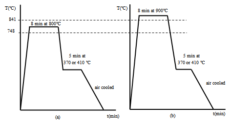 | Figure 1. Heat treatment schedules to produce TRIP-aided steels with a) polygonal ferrite (PF) and b) bainitic ferrite (BF) matrices |
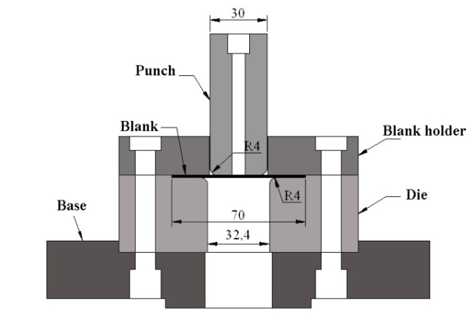 | Figure 2. Schematic design of the apparatus used for swift cup test |
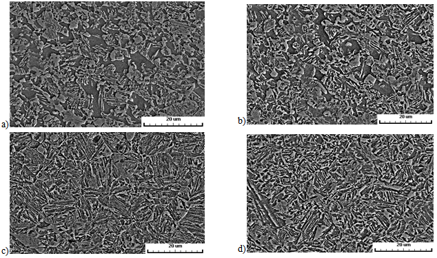 | Figure 3. SEM micrographs of heat treated samples a) PF370, b) PF410, c) BF370 and d) BF410 |
|
3. Results
3.1. Microstructure and Morphologies of Retained Austenite
- Fig. 3 shows SEM micrographs of austempered steels at different annealing and austempering conditions, as described in Table 2.The samples which annealed at 800˚C (PF370, PF410) have a polygonal ferrite (PF) matrix and the ones which annealed at 900˚C (BF370, BF410) contain bainitic-ferrite (BF) matrix (Fig. 3). Three types of retained austenite morphologies are observed in both microstructures; blocky, island-like and film-like. Morphology of retained austenite in PF370 and PF410 samples is mainly blocky type (Fig. 3a and b), while film-like and island-like morphologies are prominent in BF370 and BF410 samples (Fig. 3c and d). It is also evident that the amount and size of blocky retained austenite in BF410 sample are greater than those of BF370 sample.
3.2. Volume Fraction and Carbon Content of Retained Austenite
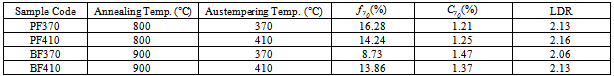
- Variations in initial volume fraction (fγ0) and initial carbon content (Cγ0) of retained austenite in the steel sheets are listed in Table 2 at different heat treatment conditions. Amount of retained austenite is higher in the steels with PF matrix, while retained austenite in the steels with BF-matrix has higher carbon content, indicating its higher stability[18]. The results are in good agreement with other researches[18-19].
3.3. Deep Drawability
- Deep drawability of austempered steel sheets in term of LDR is also listed in Table 2. Maximum and minimum values of LDR are obtained in PF410 and BF370 samples, respectively, whereas deep drawability of BF410 sample is comparable to that of PF370 sample. Fig. 4 shows the punch load-stroke curves for all deep drawn samples with blanks of 70mm diameter. PF410 sample with mainly blocky type retained austenite exhibits the highest stroke, as a measure of deep drawability. In contrast, BF370 sample with film-like and island-like retained austenite presents the lowest strokes, which is in accordance to the LDR results. Further, it can be stated that PF370 sample provides better deep drawability than BF410 sample (Table 2).
4. Discussion
4.1. Effects of Volume Fraction and Stability of Retained Austenite on Deep Drawability
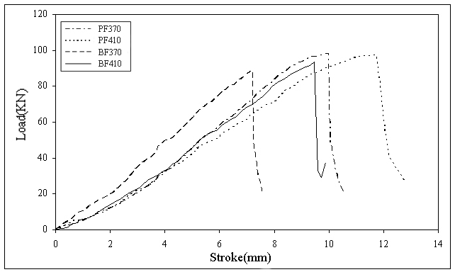 | Figure 4. Load-stroke curves of deep drawing test for blanks with 70mm diameter |
4.2. Comparison of Deep Drawability of Steels with BF and PF Matrices
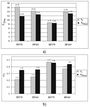 | Figure 5. a) Volume fraction and b) carbon content of retained austenite in blanks with 70mm diameter and in flange portion after 8mm drawing |
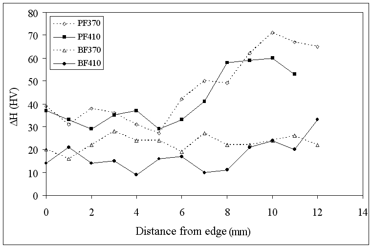 | Figure 6. Hardness profile in flange area of blanks with 70mm diameter after 8mm deep drawing process |
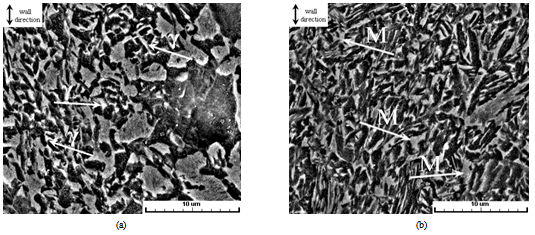 | Figure 7. SEM micrographs in shoulder portion of completely drawn blanks, with 60 mm diameter, (a) PF410 and (b) BF410 samples. Arrows indicate (left) retained austenite and (right) martensite phases |
- Hardness results (Fig. 6) also confirm higher hardness of flange area in the PF samples rather than in the BF samples. This is apparently in contrast to LDR results. The discrepancy could be explained by microstructural observations. SEM micrographs (Fig. 7) demonstrate that stability of retained austenite in the drawn BF410 sample is too high to promote martensitic transformation in its cup wall (shoulder portion), which reduces deep drawability of the sample. Therefore, better deep drawability of PF410 sample is attributed to formation of higher amount of strain induced martensite in its cup wall.The effect of matrix morphology is also considerable from work hardening view point. The work hardening resulting from strain induced martensite increases by hardness difference between matrix and martensite phase[23]. The difference enhances when the matrix becomes softer or the martensite product is harder. However, the later happens as carbon content of retained austenite increases, while this coincides with higher stability of the retained austenite and reduces deep drawability of the sample. Therefore, the remained way to increase the influence of TRIP effect on work hardening is to reduce the hardness of the matrix. This occurs in PF samples, as polygonal ferrite is softer than bainitic-ferrite phases, and hardness difference between PF matrix and martensitic product becomes higher. Hence, work hardening due to martensitic transformation in the polygonal ferrite matrix is greater than that of the bainitic-ferrite matrix and the PF samples can offer higher deep drawability.
5. Conclusions
- Deep drawability of conventional polygonal ferrite and bainitic-ferrite TRIP-aided steels has been studied and compared in term of LDR, employing swift cup test. Also effects of microstructure and retained austenite characteristics on deep drawability of both steels are evaluated and summarized as follow:1- Increasing volume fraction of retained austenite intensifies the contribution of TRIP effect in the steel and improves the deep drawability.2- Deep drawability of TRIP-aided steels improves as stability of retained austenite is in a level which small martensitic transformation occurs in the flange area, and large martensitic transformation happens in the shoulder portion of the cup.3- Higher hardness difference between matrix and martensitic products provides a better deep drawability in TRIP-aided steels.