Vivekanandan. P 1, Arunachalam. V. P 2, Prakash. T 3, Savadamuthu. L 2
1Mechatronics Engineering, SNS college of Technology, Coimbatore, 641035, India
2SNS college of Technology, India
3KPR Institute of Engineering & Technology, India
Correspondence to: Vivekanandan. P , Mechatronics Engineering, SNS college of Technology, Coimbatore, 641035, India.
| Email: |  |
Copyright © 2012 Scientific & Academic Publishing. All Rights Reserved.
Abstract
This research is to study the influence of friction stir welding on the microstructure and hardness of aluminium 6035 and 8011. The parameters which influence the friction welding are rotational speed of 550 rpm and welding speed of 40-90 mm/min. As a result of the experiment it had been found that maximum tensile strength is 50 N/mm2 for welding speed of 60 mm/min. The hardness test results showed the maximum obtainable hardness as 91 HV at weld center. The microstructure test results showed that the high tensile strength and hardness is obtained in the friction stir welded zone of aluminium 8011.
Keywords:
Aluminium Alloy AA6035, AA8011, FSW, Butt Joints, Tensile Strength
Cite this paper:
Vivekanandan. P , Arunachalam. V. P , Prakash. T , Savadamuthu. L , "The Experimental Analysis of Friction Stir Welding on Aluminium Composites", International Journal of Metallurgical Engineering, Vol. 1 No. 4, 2012, pp. 60-65. doi: 10.5923/j.ijmee.20120104.03.
1. Introduction
For the materials that are difficult to weld by fusion welding (Conventional Fusion Welding) a friction stir welding has been used effectively in the industry production of vehicles and vessels. The mechanical properties of the friction stir welded materials are higher than the conventional welding methods. Process of a friction stir welding is shown in Fig. 1Probe is inserted into the seam of the material causes the material to heat and soften, stirring motion is experienced around the shoulder of the tool .Tool will be transferred to the rear in the direction of rotation of the stirring stick to the retreating side. It had some of material flow back to the front of advancing side. (The retreating side is the direction of rotation of the stirring, the opposite direction and the advancing side is the direction of rotation of the disperser parallel to the direction of welding) when the material is passed around probe and some will move to the back of the shoulder again. Shoulder of the tool will compress the material back into the cause of a welding together. The current research is about FSW in various grades of aluminium, such as study and the influence of the rotation speed of tool which affects the mechanical properties of aluminium alloys in AA6035.The study of a stir at the end of the cylindrical cutting curves and straight cuts which affects the mechanical properties of aluminium alloy AA6035.The size of the shoulder of the tool and the diameter tool affects the grades of aluminium alloy AA6035.These studies have reported that strength of these butt joints are higher than the aluminium used in welding materials.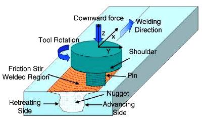 | Figure 1. Schematic drawing of friction stir welding |
2. Experimental Procedures
2.1. Welding Parameters
In this study, downward force and tool rotational speed are kept constant, only the welding speed is varied. The welding parameters at which the optimum results are obtained are given in Table1.
2.2. Tool Composition
Straight cylindrical tool was used. The tool is made up of High speed steel and which was tempered and hardened to 50 HRC. The tool material composition is given in Table 2.| Table 1. welding parameters |
| | WELDING SPEED (mm/min) | 60 | | TOOL ROTATIONAL SPEED (rpm) | 550 |
|
|
| Table 2. Tool composition |
| | MATERIAL | C | Cr | W | Mo | V | Fe | | HSS | 0.85 | 40 | 6.0 | 5.0 | 2.0 | Remaining |
|
|
2.3. Tool Geometry
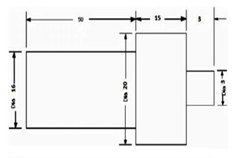 | Figure 2. Tool Geometry All Dimensions are in mm |
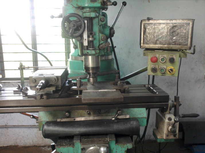 | Figure 3. FSW Vertical Milling Machine |
From the survey of literature it was found FSW welding has been carried out by using complicated tool geometries, which are extremely difficult to manufacture. But it was observed that the complicated tool pin profiles tend to wear out after few numbers of runs leading to a conical form. This has been occurred specially while working with comparatively higher tensile strength materials. Hence in the present work it is decided to study the performance of FSW tools having simple regular geometrical forms, like straight tapered cylindrical as shown in Fig.2. On prolonged usage, even if these tools wear down, they will attain tapered cylindrical or cylindrical shape. Therefore a systematic study of these regular simple geometric shapes was taken up. To carry out the FSW experiment a vertical milling machine with 5hp motor capacity was used as shown in Fig.3. The tool was mounted in the vertical arbor using a suitable collates. The plates to be joined were clamped to the horizontal bed with zero root gap. The clamping of the test pieces was done such that the movement of the plates was totally restricted under both plunging and translational forces of the FSW tool. The tool rpm and translational speed of the bed were set prior to each run of welding. After plunging the rotating tool is made to rotate at the joining area of the AA6035 and AA8011 aluminium plates.
2.4. Work Piece
The starting materials were monolithic cold-rolled plates of AA 6035 and AA8011 aluminium alloy with a nominal composition as shown in the table 3. The surface of plates was cleaned with grinding paper before processing. The dimensions of the workpiece were 210 mm×75 mm×5 mm and are cut on both the aluminium alloys of AA6035 and AA8011. The wor kpiece of both aluminium alloys is attached at the edge and it is fixed into the work table rigidly as shown in Fig 4. | Figure 4. The dimension of the specimen (unit: mm) |
| Table 3. chemical composition |
| | CHEMICALCOMPOSITION | Si | Fe | Cu | Mg | Al | | AA 6035 | 1.007 | 0.242 | 0.007 | 0.613 | Remaining | | AA 8011 | 0.826 | 0.182 | 0.000 | 0.133 | Remaining |
|
|
3. Results and Discussion
The results of testing the tensile strength at 550 rpm welding speed with the feeds of 40,60 and 90 millimetres per minute, is shown in Fig. 5. It shows that the tensile strength of 50N/mm2 is the maximum for welding speeds to 60 mm/min and is slightly lower at 40 mm/min and 90 mm/min.The hardness test results showed that the highest measured hardness is 91 HV at weld center at a welding speed 60 mm/min which can be observed from Fig.6. The hardness values at other welding speeds are lower. The center is expected to weld the aluminium alloy 8011 with a non-homogenous 6035 aluminium alloy. We could notice that the left hand side of the AA 6035 is a value that is lower than the center as expected of them as a tool to bring material AA 8011 was merged with the AA 6035, making the hardness high over the center line. In case of lowest hardness 53 HV at the speed of 200 mm per minute is applied. The observer will notice that the values are close to the base material of aluminium alloy 6035, as tools carry material of aluminium alloy 6035.Fig. 7 & 8 shows the microstructure of the work piece, till the speed of 550 rpm and welding speed to 60mm/min. Fig.7 shows the structure grain growth of aluminium alloy 6035. The structure of this grain growth affects the tensile strength. The erosion of work tries to collapse the core material. Fig. 8 shows the microstructure of the aluminium 8011. We could notice that some areas of white on black. When testing the hardness of this region it was much lower than aluminium alloy 6035. Fig.8 shows the microstructure of the weld, which is noted that the grain is fine (10 µm.) than the microstructure of aluminium alloy 6035. This fine structure affects the tensile strength and hardness (i.e. makes the test value higher).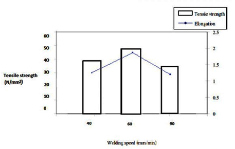 | Figure 5. The relationship between welding speed and tensile strength |
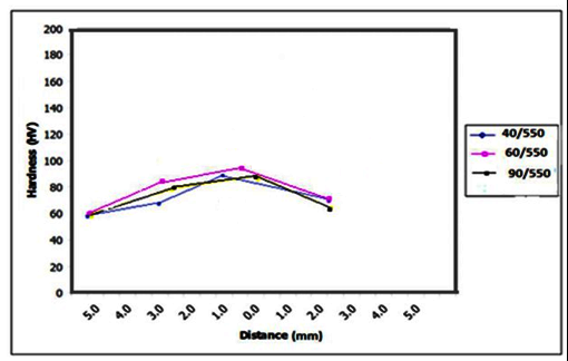 | Figure 6. Result of Hardness Testing |
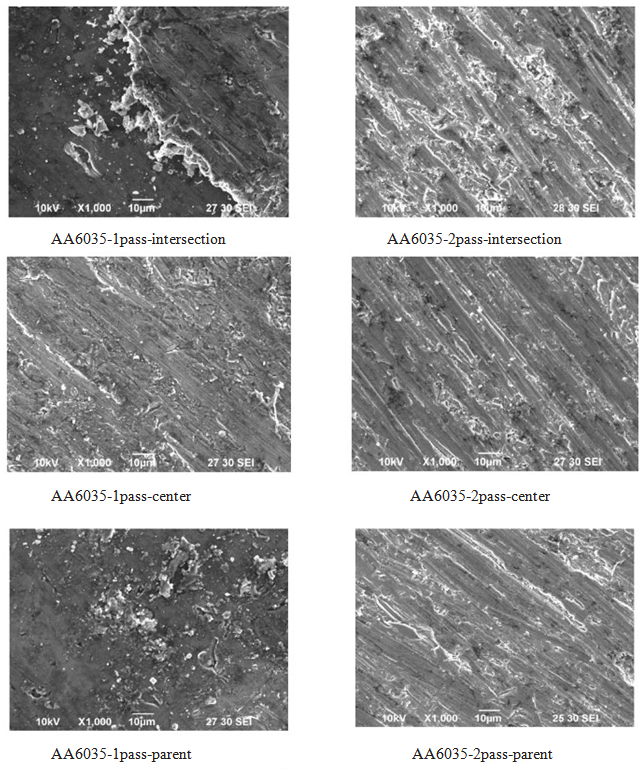 | Figure 7. Microstructure of AA6035 1 pass and 2 pass for (a) parent (b) centre (c) Intersection |
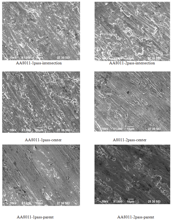 | Figure 8. Microstructure of AA8011 1 pass and 2 pass for (a) parent (b) centre (c) Intersection |
4. Conclusions
The experimental application of a friction stir welding of the butt joints between aluminium AA6035 and AA8011 by changing the feed rate had influenced the microstructure and hardness of aluminium 6035 and 8011. The results are as follows1. Conditions speed 550 rpm and a welding speed of 60 mm / min. The weld is complete and tensile strength is 50 N/mm2.2. The maximum hardness of 91 HV at a welding speed of 60 mm / min, which resulted in a high tensile strength.3. The weld zone was divided into three regions (center of weld, AA6035, AA8011) based on the microstructure. The center of weld had fine grains due to dynamic recrystallization with higher tensile strength and hardness.
References
| [1] | Thomas, W.M. and Nicholas, E.D. 1997.Friction Stir Welding for the Transportation Industries. Materials and Design 18: 269-273 |
| [2] | Kittipong Kimapong 2551. Influence the feed speed of the friction stir welding by the tensile strength of the butt joints of aluminum6035-T1. Engineering research and development: 47-51. |
| [3] | A.Squillace, T.Segreto, U.Prisco, Teti, G.Campanile 2006. Optimization of Friction Stir Welds of Aluminium alloys. IPROM, 135: 189-195. |
| [4] | Bunjurd Donnetham and Somnuk Watthanasikul. 2550. Comparison of the friction stir welding of aluminium alloy AA6063-T6 between cylindrical and rounded head. IE network conference 2007. Phuket, Thailand, 24-26 October 2007 :CD Rom |
| [5] | Elangovan, K., Balasubramanian, V. 2008.Influences of tools pin profile and tool shoulder diameter on the formation of friction stir processing zone in AA6035 aluminium alloys. Materials and Design 29: 362-373. |
| [6] | Vural, M., Ogur, A., Cam, G.,Ozarpa, C. 2007. On the friction stir welding of aluminium alloys EN AW 2024-0 and EN AW 5754-H22. Mat.Sci. and Eng.A, 28: 49-54. |
| [7] | Cavaliere, P., Cerri, E. 2005.Mechanical response of 2024-8011 aluminium alloys joined by Friction Stir Welding. Journal of Materials Science. 40: 3669-3679. |
 Abstract
 Reference
 Full-Text PDF
 Full-Text HTML