Fernando Rodrigues Pillon1, Roberto Vasconcelos Pinheiro1, Aksou Vítor Kestring Vera1, Felipe Nascimento Arroyo2, André Luis Christoforo3, Túlio Hallak Panzera4, Francisco Antônio Rocco Lahr5
1Departmente of Civil Engineering, University of Mato Grosso State (UNEMAT, Sinop, Brazil
2Integrated Colleges of Cacoal (UNESC), Cacoal, Brazil
3Centre for Innovation and Technology in Composites (CIT C), Department of Civil Engineering, Federal University of São Carlos (UFSCar), São Carlos, Brazil
4Centre for Innovation and Technology in Composites (CIT C), Department of Mechanical Engineering, Federal University of São João del-Rei, São João del-Rei, Brazil
5Department of Structural Engineering (SET), São Carlos Engineering School, São Paulo University (EESC/USP), São Carlos, Brazil
Correspondence to: André Luis Christoforo, Centre for Innovation and Technology in Composites (CIT C), Department of Civil Engineering, Federal University of São Carlos (UFSCar), São Carlos, Brazil.
| Email: |  |
Copyright © 2018 The Author(s). Published by Scientific & Academic Publishing.
This work is licensed under the Creative Commons Attribution International License (CC BY).
http://creativecommons.org/licenses/by/4.0/

Abstract
The aim of this study is the technical-economic analysis of buildings from 3 to 21 storey, applying different characteristic resistance values at 28 days (fck), varying between 25 and 40MPa, with a geometric relation, in plant, of 1:1. By means of the obtained results, it is estimated that it is possible to assist the structural design, the sizing and, mainly, to subsidize the budgeting of the structure of buildings in reinforced concrete with the same geometric relation. The results and data organization were obtained through structural analysis software and electronic spreadsheets. The applied research methods were subdivided into architectural design, structural design, stability analysis, cost composition and technical-financial analysis. With the results, it can be concluded that: (i) the increase in fck value significantly altered the steel consumption of the pillars, presenting different behaviors according to the height of the building; (II) the average thickness of the pavements type and the consumption of mold presented a slight reduction with the increase of the value of fck; (III) the use of C-35 concrete results in lower overall costs for buildings up to 15 floors and C-40 concrete for buildings of 18 and 21 floors.
Keywords:
Reinforced concrete structures, Ribbed slab, Variation of the compressive strength
Cite this paper: Fernando Rodrigues Pillon, Roberto Vasconcelos Pinheiro, Aksou Vítor Kestring Vera, Felipe Nascimento Arroyo, André Luis Christoforo, Túlio Hallak Panzera, Francisco Antônio Rocco Lahr, Technical and Economic Analysis of Structures of Buildings in Reinforced Concrete with Ribbed Slab from 3 to 21 Floors, International Journal of Materials Engineering , Vol. 8 No. 6, 2018, pp. 142-151. doi: 10.5923/j.ijme.20180806.02.
1. Introduction
With the accelerated urbanization process that Brazil has undergone in the last decades, spaces, especially the urban, have suffered too much real estate appreciation mainly in the central zones of the cities, which ends up making the construction of ground buildings financially unfeasible. For a better use of these, we have as an alternative the verticalization, which allows gathering a greater number of people in the same space [1].Nowadays, increasingly tall and slender buildings have been built due to the technological innovations in the engineering area, especially in structural and concrete computational software with the highest characteristic resistance to compression (fck) [2].In the case of reinforced concrete buildings, the use of concrete with higher compressive strengths results in a reduction in the cross-section of the structural elements, reducing the volume of concrete to be used. However, the adoption of these concrete with the intention of reducing costs can be questioned due to its higher price [2].The present work aims to study a hypothetical building designed with ribbed slab with a 1:1 geometric relation in plan, associating concrete with different compressive strengths (25, 30, 35 and 40MPa) in order to check the quantity of inputs (concrete, steel and forms). The hypothetical building under study consists of type pavements, varying the repetitions number (3, 5, 7, 10, 13, 15, 18 and 21).
2. Material and Methods
The research was developed in five stages: definition of the architectural project respecting the geometric relation in a 1:1 plan (20m x 20m); design of the structure and definition of actions in the structure; dimensioning and verification of the structural elements together with the verification of the overall stability of the building; obtaining of the quantitative of the inputs (concrete, steel and mold) as well as its composition of cost; and definition of the technical and financial parameters of the project under study.First step - architectural designThe architectural designs contain the following characteristics: geometric relation in a plant around 1:1, with approximate dimensions of 20 meters x 20 meters according to Figure 1, and height between floors of three meters.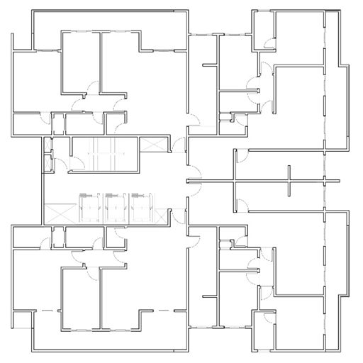 | Figure 1. Low plant |
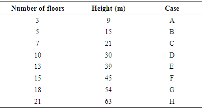
The differences between the buildings are only the number of repetitions of the type pavements, which vary from 3 to 21 repetitions, classified in cases that vary from "A" to "H" according to Table 1.Table 1. Proposed cases in relation to the number of floors
 |
| |
|
Second stage - Structural design, actions and uploadsThe structure was conceived respecting the architectural design and meeting all the requirements regarding the transfer of actions and stability of the building.The structural design started by the positioning of the pillars, later the external beams and the slabs. The pillars were initially arranged around the pavement and inside the building. As for the beams, these were leased only in the contours of the pavement, since the use of ribbed slab dispenses with the use of internal beams. The beams located in the outline of the pavement delimit the outline of the slab. The structural design is shown in Figure 2.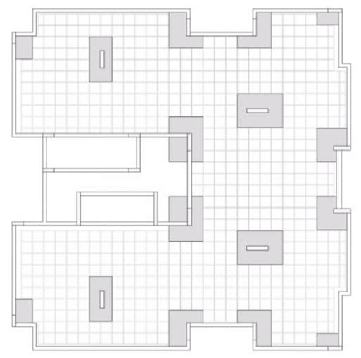 | Figure 2. Structural design |
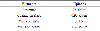
According to the provisions of the norms ABNT NBR 6120:1980 [4] and ABNT NBR 6118:2014 [3], the vertical acting actions were defined. Based on ABNT NBR 6120:1980 [4], the specific weights of the structural and non-structural elements that make up the weight of the building were defined.For the structural elements, the specific gravity of the reinforced concrete in unit force per cubic meter was considered. The weight of the coating on the slabs is composed of the weights of the subfloor and the coating in unit of force per square meter. In the weight of the walls on slabs or beams, the weights of the ceramic blocks, the laying mortar and the plaster were considered in unit of force per linear meter, according to Table 2.Table 2. Weight of structural and non-structural elements
 |
| |
|
The variable actions, according to ABNT NBR 6120:1980 [4], were composed of utilization overloads, divided into: 1.5 kN/m² for dormitories, rooms, kitchens, bathrooms and canopies; 2 kN/m² for service area, pantry, laundry; 3kN/m² for stairs and corridors with access to the public; and 2 kN/m² for terraces without access to the public.The contour of the slabs is defined by the beams and, as previously said, in projects with ribbed slabs there is no need to use internal beams, just in the outline of the building, creating large slabs that encompass the entire floor.For this project, the apartments of the pavement type are situated on only a large slab with approximately 460sqm, so there is no possibility to distinguish the environments. For residential buildings, the usage overload varies from 1.5 to 2 kN/m², depending on the environment. Thus, the utilization overhead adopted was the highest between the two cases, 2 kN/m².Based on NBR 6123:1988 [5], the horizontal variable actions, derived from wind forces, were defined. According to it, some parameters needed to be defined for the determination of these actions. The basic wind speed was defined for the city of Sinop/MT, being 30m/s according to the isopleth map of Figure 3 extracted from the standard.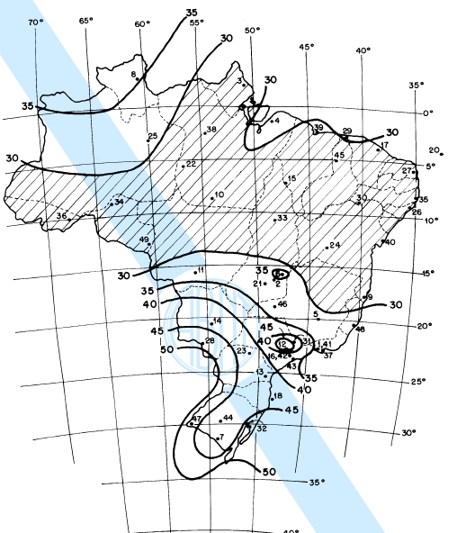 | Figure 3. Map of basic wind speed isopleths |
The topographic factor considers variations in terrain relief. By adopting the flat or weakly uneven terrain, the topographic factor is defined as S1 = 1.0 (Item 5.2).Factor S2 considers the combined effect of terrain roughness, wind speed variation with height above ground and dimensions of the building or part of the building under consideration. In determining factor S2, category III and class "C" were defined.To determine the statistical factor, the proposed cases were classified as belonging to group 2 of item 5.4 of the standard. Therefore, factor S3 was defined as 1.0.The drag coefficients (Ca) were calculated for each type of pavement by means of the abacus of Figure 4 of ABNT NBR 6123:1988 [5], considering the heights relative to each pavement as well as the dimensions of the building plan.In accordance with ABNT NBR 6118:2014 [3], some parameters were defined for the structural elements: environmental aggression - class II; covering of reinforcements (external environments) of 2.5 and 3.0 cm for slabs and pillars/beams respectively; maximum aggregate diameter - 19 mm; fck (25, 30, 35 and 40 MPa); and fyk (CA50 for beams and slabs, and CA50 and CA60 for pillars).Third step - Analysis, sizing and structural verificationAfter the structural elements were released, the checks recommended by ABNT NBR 6118:2014 [3] were carried out.Based on the final boundary states, concrete checks and armor sizing were performed. Based on the service limit state, the vertical and horizontal displacements of the structural elements were verified.It was sought to improve the abutments by means of the relation of the resistant moment by the requesting moment (Mrd/Msd), looking for dimensions with close relation of 1.0.Taking the coefficient γz as the criterion of relevance, we verified the effects of first and second order in the global analysis of the structure and in relation to the displacements.Fourth stage - Mapping of the quantitative and composition of the cost of the inputsAfter the sizing and verification of the structural elements, the quantitative steel, concrete and forms were generated by the structural analysis software.Based on the SINAPI/MT table of October 2017, the compositions of input costs, equipment cost indices and labor productivity were made.Fifth stage - Technical-financial parametersAfter the mapping of the quantitative and the cost composition of the inputs, the technical-financial parameters of each building (from 3 to 21 floors) with each characteristic resistance to the compression of the concrete used in the project (25 to 40 MPa) were defined, in order to obtain the best relation for each case.The determined parameters were: steel consumption (kgsteel/m3concrete); consumption of molds (m2formwork/m3concreto); average floor thickness (in centimeters); and average cost of the building (R$/m²).
3. Results and Discussion
Cases "A" and "B"Steel consumption - slab elementSteel consumption for the "A" and "B" slabs decreased as the concrete strength increased. The case "A" presented steel consumption ranging from 127.8 kgsteel/m³concrete to fck 25 MPa to 114.8 kgsteel/m³concrete to fck 40 MPa, a reduction of 10.14%.The "B" case presented steel consumption ranging from 130.5 kgsteel/m³concrete, to fck 25Mpa, to 115.9 kgsteel/m³concrete, to fck 40 MPa, obtaining a reduction of 11.20%. The steel consumption data are represented by the graph of Figure 4.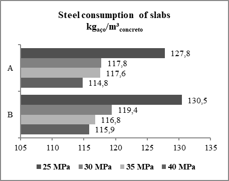 | Figure 4. Steel consumption of slabs for cases "A" and "B" |
The coefficients of variation were 4.76% and 5.57% for cases "A" and "B", respectively. The average consumption of case "A" was 119.5 kgsteel/m³concrete and, for case "B", 120.6 kgsteel/m³concrete.Steel consumption - beam elementThe steel consumption for the beams of cases "A" and "B" remained constant as the concrete strength increased. Case "A" presented average steel consumption of 73.5 kgsteel/m³concrete with a coefficient of variation of 2.02%.Case "B" presented average steel consumption of 75.7 kgsteel/m³concrete with a coefficient of variation of 2.41%.Steel consumption - pillar elementWith the increase in concrete strength, the steel consumption for the pillars in relation to the concrete consumption in cases "A" and "B" increased.However, these data are explained when analyzing the volume of concrete and the mass of steel. It was noticeable that both reduce with the increase of the resistance of the concrete. The concrete has a more significant reduction in relation to the steel, reaching a reduction of 46.89% in the volume required according to Figure 5, while the steel presents a reduction in the mass that reaches 37.32% according to Figure 6.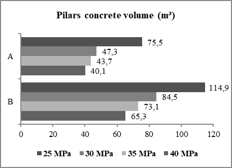 | Figure 5. Concrete volume of the pillars for cases "A" and "B" |
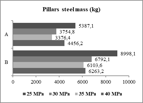 | Figure 6. Steel mass of the pillars for cases "A" and "B" |
If the volume of concrete reduces at a higher rate than the mass of steel, the ratio of steel mass per volume of concrete (kg/m³ concrete) tends to increase even with reduction in the consumption of both inputs.Formwork consumptionThere was a slight reduction in the form consumption according to the increase in concrete strength, as shown in Figure 7, with a coefficient of variation of 2.58% for case "A" and 2.51% for case "B ". The average form consumption was 3,69m²formwork/m³concrete and 3,72m2formwork/m³concrete for the cases "A and B" respectively.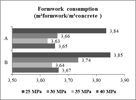 | Figure 7. Formwork consumption for cases "A" and "B" |
Average floor thicknessTo obtain an estimate of the volume of concrete to be used in a building, the average thickness of the pavement is used as a reference. This parameter considers the total volume of concrete distributed over the total floor area.For the proposed cases, the average thickness of the pavement type presented a slight reduction with the increase of the resistance of the concrete, as shown in Figure 8, characterizing coefficient of variation of 3.47% for case "A" and 3.12% for the "B" case. The average thickness of the pavement type was 21 cm for both cases.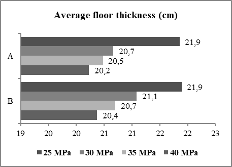 | Figure 8. Average floor thickness for cases "A" and "B" |
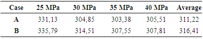
Average cost of buildingBased on the amounts generated by the structural analysis software and the price of inputs extracted from the SINAPI table of October 2017, an estimated value of the structure cost per square meter of construction, in R$/m², was calculated for the proposed cases, listed in Table 3.Table 3. Average cost of building (R$/m²) for cases "A" and "B"
 |
| |
|
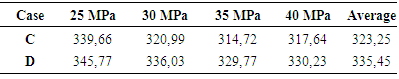
Note that for both cases, the C-35 concrete was the one that presented the lowest cost. Compared with the C-25 concrete that presented the highest cost in both cases, the economy was 8.38% for case "A" and 8.41% for case "B".This behavior is justified because the C-40 concrete, despite providing a reduction in the quantity of inputs, has a higher price.Cases "C" and "D"Steel consumption - slab elementAnalogously to the "A" and "B" cases, as the concrete strength increased, steel consumption for the "C" and "D" slabs declined gradually. The "C" case presented average steel consumption of 123.5 kgsteel/m³concrete with a coefficient of variation of 4.06%. For the case "D" the reduction was less significant, being able to be considered constant with a coefficient of variation of 1.41% and an average consumption was of 124.0 kgsteel/m³concrete.For both cases, the lowest steel consumption was found with the use of C-40 concrete and were 123.8 kgsteel/m³concrete for case "C" and 120.5kgsteel/m³concrete for "D" case.Steel consumption - beam elementThe steel consumption, for the "C" and "D" beams, remained constant as the concrete strength increased. Case "C" presented average steel consumption of 78.6 kgsteel/m³concrete with a coefficient of variation of 2.03%.Case "B" presented average steel consumption of 83.4 kgsteel/m³concrete with a coefficient of variation of 2.06%.Steel consumption - pillar elementSimilar to cases "A" and "B", steel consumption for the "C" and "D" pillars increased as the concrete strength increased. The "C" case presented average steel consumption of 89.6 kgsteel/m³concrete with a coefficient of variation of 5.28%.The "D" case presented average steel consumption of 81.2 kgsteel/m³concrete with a coefficient of variation of 7.92%.For both cases, the lowest steel consumption was found with the use of the C-25 concrete and were 89.8 and 81.6 kgsteel/m³concrete for the "C and D" cases, respectively.Formwork consumptionSimilar to the previous cases, there was a slight reduction in the formwork consumption according to the increase in concrete strength, with a coefficient of variation of 2.20% for case "C" and 1.72% for case "D". The average form consumption was 3.74 and 3.80 m²formwork/m³concrete for the "C and D" cases, respectively.Average floor thicknessFor the proposed cases, the average thickness of the pavement presented a slight reduction with the increase of the resistance of the concrete. A coefficient of variation of 2.50% and thickness of 21 cm were obtained for the case "C" and coefficient of variation of 2.72% and thickness of 22 cm for the "D" case.Average cost of buildingThe "C" and "D" cases presented a slight reduction in the cost of the structure according to the increase of resistance in the concrete until reaching its minimum value with the use of the C-35 concrete. From the use of the C-35 concrete, the increase of resistance increased the cost of the structure. This behavior can be seen from Table 4.Table 4. Average cost of building (R$ / m²) for cases "C" and "D"
 |
| |
|
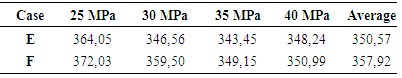
The "C" case presented a coefficient of variation of 3.48% and an average cost of 323.25 R$/m²building. The "D" case presented a coefficient of variation of 2.22% and an average cost of R$ 335.45/m²building.Cases "E" and "F"Steel consumption - slab elementSimilar to the previous cases, steel consumption for the slabs of the "E" and "F" cases decreased slightly as the concrete strength increased. The "E" case presented a coefficient of variation of 2.35% and an average steel consumption of 122.9 kgsteel/m³concrete.On the other hand, the "F" case presented an average consumption of 118.0 kgsteel/m³concrete and a coefficient of variation of 2.49%. For both cases, the lowest consumption was obtained with the use of C-35 concrete.Steel consumption - beam elementSteel consumption, for the "E" beams, remained constant as the concrete strength increased. This case presented average steel consumption of 93.3 kgsteel/m³concrete with a coefficient of variation of 3.27%.The "F" case presented a slight increase in steel consumption as the concrete strength increases. This case presented average steel consumption of 100.1 kgsteel/m³concrete with a coefficient of variation of 5.17%. This increase is due to the drop in concrete volume being more pronounced than the fall in the steel mass.Steel consumption - pillar elementUnlike the previous cases, the steel consumption in the columns, for the "E" and "F" cases, decreased with increasing concrete strength. The "E" case presented an average steel consumption of 82.1 kgsteel/m³concrete with a coefficient of variation of 2.93%. The lowest steel consumption was 81.9 kgsteel/m³concrete, obtained with the use of concrete with 40 MPa of resistance.The "F" case presented a less significant reduction, with a coefficient of variation of 1.70% and an average consumption of 86.1 kgsteel/m³concrete. In this case, the lowest consumption was 85.3 kgsteel/m³concrete, obtained with the use of a concrete of class C-40. The steel consumption values for the columns are shown in Figure 9.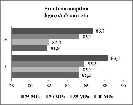 | Figure 9. Steel consumption of the columns for the "E" and "F" cases |
Formwork consumptionSimilar to the previous cases, there was a slight reduction in the formwork consumption as the increase in concrete strength, with a coefficient of variation of 1.68% for case "E" and 1.98% for case "F". The average form consumption was 3.88 concrete and 3.94m²formwork/m³concreto for the cases "E" and "F" respectively.Average floor thicknessFor the proposed cases, the average thicknesses of the type pavements presented a slight reduction with the increase of the resistance of the concrete, characterizing coefficient of variation of 3.10% and 3.18% for the cases "E" and "F" respectively. Thus, the average floor thickness equivalent to 23 cm can be fixed for both cases.Average cost of buildingIn a similar way to the previous cases, the cost of the structure reached its lowest value with the use of C-35 concrete, according to Table 5.Table 5. Average cost of building (R$ / m²) for cases "E and F"
 |
| |
|
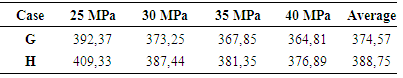
The coefficients of variation of the cost of the structures were of 2.62% and 2.91% for the cases "E" and "F" respectively. When comparing C-25 concrete with C-35, there is a reduction in structure cost of 5.66% for "E" case and 6.15% for "F" case.Cases "G" and "H"Steel consumption - slab elementAccording to the increase in concrete strength, the steel consumption for the "G" and "H" slabs decreased gradually. The "G" case presented average steel consumption of 118.8 kgsteel/m³concrete with a coefficient of variation of 1.43%. For the "H" case, the average consumption was 116.4 kgsteel/m³concrete with a coefficient of variation of 2.54%.For both cases, the lowest steel consumption was found using the concrete with 40MPa and was 117.6 and 114.0 kgsteel/m³concrete for the cases "G" and "H" respectively. This behavior was expected because the sections of the slabs were not altered.Steel consumption - beam elementSteel consumption for the "G" beams increased gradually as the concrete strength increased due to the drop in concrete consumption being more pronounced than the reduction in steel consumption. This case presented an average consumption of 109.6 kgsteel/m³concrete and a coefficient of variation of 4.24%.The steel consumption, for the "H" case beams, remained constant as the concrete strength increased. The "H" case presented average steel consumption of 114.4 kgsteel/m³concrete with a coefficient of variation of 1.46%.Steel consumption - pillar elementSimilar to the "E" and "F" cases, the steel consumption in the pillars for "G" and "H" cases decreased with increasing concrete strength. The "G" case presented an average steel consumption of 96.0 kgsteel/m³concrete with a coefficient of variation of 14.86%. The lowest steel consumption was 79.9 kgsteel/m³concrete, obtained with the use of concrete with 35Mpa of resistance.The "H" case presented a less significant reduction, with a coefficient of variation of 10.63% and an average consumption of 96.7 kgsteel/m³concrete. In this case, the lowest consumption was 85.2 kgsteel/m³concrete, obtained with the use of a C-40 concrete.Formwork consumptionThere was a slight reduction in the form consumption as the increase in concrete strength, with a coefficient of variation of 1.44% for the "G" case and 0.91% for the "H" case. The average form consumption was 4.00 and 4.04 m²formwork/m³concrete for the cases "G" and "H" respectively. This behavior was presented by all other cases.Average floor thicknessThe average thickness of the type pavement had a small drop with the increase of concrete strength for the case "G". The thickness ranged from 25 cm, to fck 25 MPa, up to 23 cm, to fck 40 MPa. The mean value found was 23.8cm with a coefficient of variation of 3.83%.Similar to case "G", the "H" case presented a slight reduction in the average thickness of the type pavement as the increase of resistance in the concrete. The thickness ranged from 26 to 24cm for the concrete 25 MPa and 40 MPa respectively. The mean value found was 24,7 cm with a coefficient of variation of 3.39%.Average cost of buildingFor the proposed cases "G" and "H", the concrete that presented the lowest cost was the C-40, according to Table 6.Table 6. Average cost of building (R$ / m²) for cases "G and H"
 |
| |
|
The "G" case presented a coefficient of variation of 3.30% and an average cost of R$ 374.57/m²building. The reduction of costs with the use of concrete C-40 in relation to concrete C-25 was of 7.02%.The "H" case presented a coefficient of variation of 3.70% and an average cost of 388.75R$/m²building. For this case, the reduction in cost with the use of C-40 concrete in relation to C-25 concrete was 7.93%.Relationship between proposed cases Steel consumption - slab elementThe consumption of steel for the slabs remained constant for the different variations in the number of floors, and suffered a slight reduction with the increase of the resistance of the concrete. When analyzing all the cases, the coefficient of variation found was 3.70% and average steel consumption was 120.4 kgsteel/m³concrete.Steel consumption - beam elementThe steel consumption of the beams, for cases of "A" to "H", increased significantly as the height of the buildings increased. Each of the proposed cases had a very different average consumption of the other cases. The average consumption varies from 73.5 kgsteel/m³concrete, for case "A", up to 114.4 kgsteel/m³concrete, for case "H". An increase of 55.75%. Figure 10 represents the average steel consumption values of each proposed case.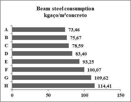 | Figure 10. Average steel consumption of each proposed case |
This behavior is justified by the action of the wind and by the second order effects resulting from these actions, in which the taller buildings are more susceptible.Steel consumption - pillar elementWhen comparing the cases of "A" to "H", we noticed a change in the behavior of steel consumption as the increase of resistance in the concrete.For low buildings, cases of "A" to "D", according to the increase of resistance in the concrete, the concrete volume reduces at a rate higher than the reduction in the steel mass, that is, the ratio kgsteel/m³concrete has a behavior increasing as fck increases. As height increases this behavior changes. For buildings from cases "E" to "H", the behavior reverses. In these cases, the steel consumption in kgsteel/m³concrete decreases as the resistance increases in the concrete. This behavior is due to the consumption of steel in kilograms falling in a proportion greater than the volume of concrete for these cases. Figure 11 shows the steel consumption behavior for the pillars of cases "B" and "H", varying fck.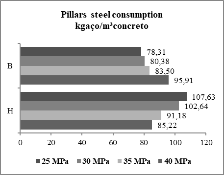 | Figure 11. Steel consumption for the pillars of cases "B" and "H" |
This behavior may be due to the absence of internal beams forming portals requiring greater stiffness of the same to contribute to the overall stability of the building.Formwork consumptionThere was a change in average consumption of forms in the comparison between each of the proposed cases. Consumption increased gradually over the increase in the number of floors, according to Figure 12.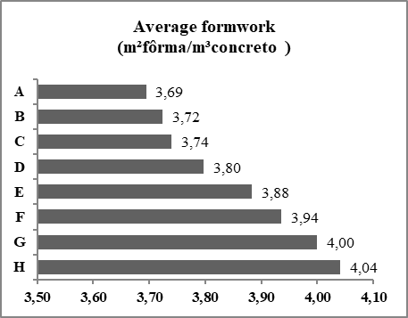 | Figure 12. Average formwork consumption |
The average consumption was 3.85m²formwork/m³concrete, and the coefficient of variation was 3.44%.Average floor thicknessIt was observed, with the comparison between the proposed cases, which the average floor thickness increases proportionally to the height of the building, with a coefficient of variation between the means of the cases of 6.32%. The average thicknesses varied from 20.8cm, for case "A", up to 24.7cm, for case "H", according to Figure 13.This behavior occurs because taller buildings are more susceptible to second-order effects generated by wind action.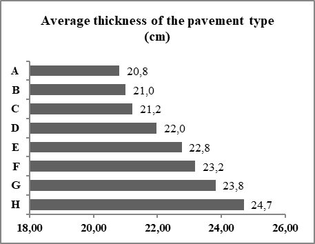 | Figure 13. Average thickness of the pavement type |
Average cost of buildingFor the cases studied, it was observed that for case "A", the C-30 concrete presented better economic performance. As for the "B" cases until the "G" case, the C-35 concrete presented the lowest cost for the structure. The "H" case presented the lowest cost with the use of C-40 concrete, but with a savings of only 0.76% compared to C-35 concrete.It was also observed that, as the increase in height occurs, the price of the structure per square meter of building increases. Figure 14 shows the average cost of each case.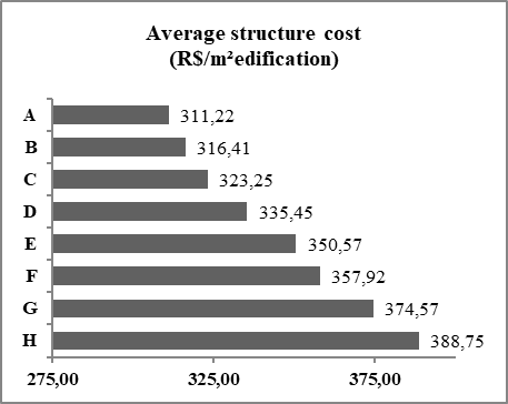 | Figure 14. Average cost of the structure for each proposed case |
This behavior is justified by the action of the wind and by the second order effects resulting from these actions, in which the taller buildings are more susceptible.
4. Conclusions
The importance of choosing fck for the elaboration of structural projects was verified with the results obtained through this study. A relation between the cost of the building and the characteristic resistance to the compression of the concrete adopted was perceived.The variation of fck did not cause significant changes in steel consumption in the beams. This altered only with the addition of pavements. Also, regarding the steel consumption, no significant changes were observed in the slabs, neither with the variation of the fck, nor with a change in the height of the building.As for the pillars, the steel consumption changed significantly with the increase of resistance in the concrete, and these alterations presented different behaviors the bigger the number of pavements in the building. As fck increased, the mass of steel in relation to the volume of concrete, for buildings up to 10 floors, rose. Already for buildings of 13 to 21 floors, a reduction occurred.The structural elements that presented the most significant reduction in concrete volume with increasing fck were the pillars, but this reduction was not very significant in a global way. The thickness has slightly increased with the increase in the number of floors due to second order effects.More resistant concretes, despite having a higher cost, provide a reduction in the consumption of inputs of the structure, generating the question of which characteristic resistance to compression provides the lowest cost in a global way. From the data obtained in this work, it was verified that for the proposed cases, from 3 to 15 floors, the C-35 concrete presented better technical-economic feasibility. Already for the cases of 18 and 21 floors, C-40 concrete was more effective.The present work provides data to facilitate the study of the feasibility of similar projects in all regions, where the basic wind speed is 30m/s, in order to guarantee the choice of the concrete with characteristic resistance to compression that provides maximum economy. The designs of multi-storey buildings have many peculiarities, making it impossible to generalize quantifications. Thus, we suggest the continuity of research on the subject addressed.
ACKNOWLEDGMENTS
I thank God first, because without Him nothing would be possible. My Family, my parents, Leandra Rodrigues and Fausto Marcelo Pillon; my brothers, Fernanda Rodrigues Pillon, Felipe Rodrigues Pillon and Guilherme Pillon; my grandparents Ilzair Terezinha Pillon and Ivone Mohr, for all support and encouragement; To my friends Ada Andressa Feroldi, Ana Paula Koerich, Bruna de Freitas Alves, Caio Vinicius Oliveira Marques, Eduardo Silva Ferreira, Igor Eduardo Fernandes de Almeida, Jéssica Luana da Silva Santos, Luana Aparecida Esser de Oliveira de Moraes, Paulo Henrique Soares de Oliveira , Ricardo Leite Dias, Thalita Raquel Souza de Oliveira Lopes and Wagner de Almeida Ferreira. To the teachers who contributed in my academic trajectory, and in particular to my teacher, Dr. Roberto Vasconcelos Pinheiro, for the effort and incentive, in order to guarantee the learning and future professional success. And finally, the State University of Mato Grosso for the academic opportunity to proudly conquer the Civil Engineering diploma.
References
| [1] | Pinheiro, L. M. Fundamentos do concreto e projetos de edifícios. 2009. 17 p. Apostila, Escola de Engenharia de São Carlos – USP, Departamento de Engenharia de Estruturas, São Carlos, 2009. |
| [2] | Giongo, J. S. Concreto armado: projeto estrutural de edifícios. 2007. 184 p. Apostila, Escola de Engenharia de São Carlos – USP, Departamento de Engenharia de Estruturas, São Carlos, 2007. |
| [3] | Associação Brasileira De Normas Técnicas. NBR 6118 – Projeto de estruturas de concreto – Procedimento. Rio de Janeiro, maio 2014. |
| [4] | Associação Brasileira De Normas Técnicas. NBR 6120 – Cargas para o cálculo de estruturas de edificações. Rio de Janeiro, nov. 1980. |
| [5] | Associação Brasileira De Normas Técnicas. NBR 6123 – Forças devidas ao vento em edificações. Rio de Janeiro, jun. 1988. |
| [6] | Associação Brasileira De Normas Técnicas. NBR 7480 – Barras e fios de aço destinados a armaduras para concreto armado. Rio de janeiro, fev. 1996. |
| [7] | Associação Brasileira De Normas Técnicas. NBR 8681 – Ações e segurança nas estruturas – Procedimento. Rio de Janeiro, mar. 2003. |
| [8] | Associação Brasileira De Normas Técnicas. NBR 8953 – Concreto para fins estruturais – classificação pela massa específica, por grupos de resistência e consistência. Rio de Janeiro, mar. 2015. |
| [9] | Associação Brasileira De Normas Técnicas. NBR 14931. Execução de estruturas de concreto – Procedimento. Rio de Janeiro, maio 2004. |
| [10] | Figueiredo Filho, J. R.; Carvalho, R. C. Análise e comportamento de sistemas estruturais em concreto - Pavimentos de edifícios. 2004. 34 f. Curso de Pós-Graduação em Construção Civil, Engenharia Civil, Universidade Federal de São Carlos – UFSCar, São Carlos, 2004. |
| [11] | Bastos, P. S. S. Estruturas de concreto armado. 2014. 63 p. Notas de Aula, Universidade Estadual Paulista – UNESP, Departamento de Engenharia, Bauru, 2014. |
| [12] | Araújo, J. M. de. Curso de concreto armado. 4. ed. Rio Grande: Dunas, 2014. |
| [13] | Costa, L. Estudo comparativo entre duas concepções estruturais de um mesmo edifício. 2012. 62 p. TCC (Graduação) - Curso de Engenharia Civil, Centro de Ciências Tecnológicas, Universidade do Estado de Santa Catarina, Joinville, 2012. |
| [14] | Goulart, M. dos S. S. Contribuição da rigidez à flexão das lajes para a estabilidade global de edifícios. 2008. 127 p. Dissertação (Mestrado) - Curso de Engenharia Civil, Universidade Federal do Rio de Janeiro, Rio de Janeiro, 2008. |
| [15] | González, M. A. S. Noções de orçamento e planejamento de obras. 2008. 49 p. Notas de Aula, Universidade do Vale do Rio dos Sinos – UNISINOS, Departamento de Ciências Exatas e Tecnológicas, São Leopoldo, 2008. |
| [16] | Pini. Engenharia de Custos aplicada à Construção Civil. Disponível em: <http://www.piniweb.com.br/empresa/download/Engenharia_custos_aplicada_a_construcao_civil.pdf>. Acesso em: 21 jun. 2017. |
| [17] | Silva, R. L. Projeto estrutural de edifícios com concretos de diferentes resistências à compressão: comparativo de custos. 2011. 40 p. TCC (Graduação) - Curso de Engenharia Civil, Escola de Engenharia, Universidade Federal do Rio Grande do Sul, Porto Alegre, 2011. |
| [18] | Spohr, V. H. Análise comparativa: sistemas estruturais convencionais e estruturas de lajes nervuradas. 2008. 108 p. Dissertação (Mestrado) - Curso de Engenharia Civil, Centro de Tecnologia, Universidade Federal de Santa Maria, Santa Maria, 2008. |
| [19] | Santos, M. V. Estudo comparativo de custo de execução de um pavimento em um edifício comercial em laje maciça e em laje lisa nervurada. 2015. 64 f. TCC (Graduação) - Curso de Engenharia Civil, Universidade Federal de Santa Maria - UFSM, Santa Maria, 2015. |
| [20] | Lanini, T. L. S.; Pinheiro, R. V. Análise técnica de estruturas de edifícios em concreto armado, de 3 a 21 pavimentos, com variação de resistência à compressão (relação geométrica, em planta, de 1:4). 2016. 10 p. TCC (Graduação) - Curso de Engenharia Civil, Faculdade de Ciências Exatas e Tecnológicas, Universidade do Estado de Mato Grosso - UNEMAT, Sinop, 2016. |
| [21] | Sá, R. T. De; Pinheiro, R. V. Análise técnica de estruturas de edifícios em concreto armado, de 10 a 21 pavimentos, com variação de resistência à compressão, numa relação geométrica, em planta, de 1:3. 2015. 11 f. TCC (Graduação) - Curso de Engenharia Civil, Faculdade de Ciências Exatas e Tecnológicas, Universidade do Estado de Mato Grosso - Unemat, Sinop, 2015. |

 Abstract
 Reference
 Full-Text PDF
 Full-text HTML