Allan Christian Alves da Luz1, Roberto Vasconcelos Pinheiro1, Felipe Nascimento Arroyo2, Diego Henrique de Almeida3, André Luis Christoforo3, Tulio Hallak Panzera4, Francisco Antonio Rocco Lahr5
1Departmente of Civil Engineering, University of Mato Grosso State (UNEMAT), Sinop, Brazil
2Integrated Colleges of Cacoal (UNESC), Cacoal, Brazil
3Centre for Innovation and Technology in Composites (CIT C), Department of Civil Engineering, Federal University of São Carlos (UFSCar), São Carlos, Brazil
4Centre for Innovation and Technology in Composites (CIT C), Department of Mechanical Engineering, Federal University of São João del-Rei, São João del-Rei, Brazil
5Department of Structural Engineering (SET), São Carlos Engineering School, São Paulo University (EESC/USP), São Carlos, Brazil
Correspondence to: André Luis Christoforo, Centre for Innovation and Technology in Composites (CIT C), Department of Civil Engineering, Federal University of São Carlos (UFSCar), São Carlos, Brazil.
| Email: |  |
Copyright © 2018 The Author(s). Published by Scientific & Academic Publishing.
This work is licensed under the Creative Commons Attribution International License (CC BY).
http://creativecommons.org/licenses/by/4.0/

Abstract
Wood, a renewable source material, has been part of the progress of mankind, being widely used in construction for centuries. However, with the passage of time, new construction techniques were being applied, new materials have been rising and, in the meantime, wood was being left out, being labelled as a material with huge incidence of pathologies. That due to its empirical use without any technical knowledge regarding its physical and mechanical properties, which still happens nowadays, being used mainly for temporary purposes. In order to show the technical viability of the use of this material as a structural element, the elaboration of projects with the following characteristics was proposed: buildings with truss structures (parallel chord) type Howe (10° inclination - steel tile); 16, 18, 20, 22, 24 and 26 meters span; side openings types of the building – 1:1, 2:1, 6:1 and open; preservative treatment. Thus, it was determined the ratio of the volume of wood (m³) and the built area (m²) for timbers classes C-20 and C-30, following the NBR 7190:1997 guidelines. With the results, it is possible to assure the real possibility of using wood species C-20 and C-30 as structural material.
Keywords:
Wood, Steel roof, Roof structures, Preservation
Cite this paper: Allan Christian Alves da Luz, Roberto Vasconcelos Pinheiro, Felipe Nascimento Arroyo, Diego Henrique de Almeida, André Luis Christoforo, Tulio Hallak Panzera, Francisco Antonio Rocco Lahr, Technical Feasibility Study for the Use of Alternative Timber in Latticework for Roofing with Spans between 16 and 26 Meters, International Journal of Materials Engineering , Vol. 8 No. 6, 2018, pp. 135-141. doi: 10.5923/j.ijme.20180806.01.
1. Introduction
Probably the first building material used by man was wood, and to this day is one of the main original ingredients used, such as versatility and ease of use, and can be applied in constructions, as the raw material for the manufacture of furniture and also as a source of energy [1].However, with the passage of time and the rapid development of technology, new building materials have been emerging, such as concrete and steel, and there is also a certain bias with wooden structures [2].This is due to the lack of awareness of owners and builders, who prefer to hire only the cheapest labor and with some practical experience, but without technical knowledge, causing a great waste of wood and constructions designed with empiricism, in which they were subject to the appearance of pathologies and excessive deformations [3]. And the explanation for these occurrences was associated with the use of wood in the structure and not with the lack of design.According to Pfeil and Pfeil [4], only in the twentieth century did wood structures gain scientific attention, gaining technical theories and patterns of use, and today it becomes an economically competitive construction material and, as a renewable material, accepted in ecological terms.In the region of Sinop/MT, in the northern state of Mato Grosso, it stands out in the timber industry due to its proximity to the sources of raw material. However, even though there are standards, wood is still used improperly, such as temporary use for shoring of slabs, sheds, scaffolding, among others. In this way, it causes a great waste and discards a material that has great potential in the civil construction [5].This work intends to show the technical feasibility of the use of alternative wood, that is, wood whose species are little used for these purposes, in lattice structures to cover sheds and to minimize the bias surrounding the use of this material for structural purposes, optimizing its use and disseminating learning in the elaboration of structural projects.
2. Material and Methods
The project was divided into five stages, in order to obtain a very detailed work, being: (i) determination of the geometric parameters of the building; (ii) structural design (arrangement of trellis components and components); (iii) actions and uploads, defining internal efforts and offsets using Ftool software; (iv) design and verification of structural elements and connections following the requirements of ABNT NBR 7190:1997 [9]; (v) quantitative survey of the volume of wood needed and organization charts. Specifications of geometric and structural parametersThe parameters of the projected buildings were as follows:- Howe isostatic trellis with parallel (10º inclination) Howe type for all gaps, with continuous upper and lower flanges (continuous bars), while diagonals and uprights are hinged at their ends, as shown in Figure 1;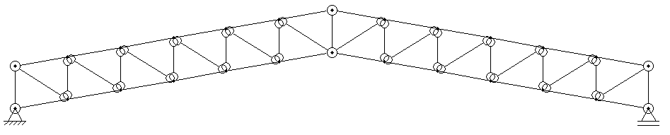 | Figure 1. Trellis structural scheme with parallel Howe-type bumpers with 10° inclination |
Steel tiles;- Right foot of 5 meters;- Building, in plan (Figure 2), with geometric relation around 1: 3, with the following specifications:• Type 1 - 16x52.5m with class C20 wood species (7 spans of 7.5 meters);• Type 2 - 18x60m with class C20 wood species (8 spans of 7.5 meters);• Type 3 - 20x60m with wood species class C20 (8 spans of 7.5 meters);• Type 4 - 22x67,5m with class C30 wood species (9 spans of 7.5 meters);• Type 5 - 24x75m with wood species class C30 (10 spans of 7.5 meters);• Type 6 - 26x82.5m with class C30 wood species (11 span of 7.5 meters).- Relation between the main opening with the other openings of the building of 1:1, 2:1, 6:1 and open.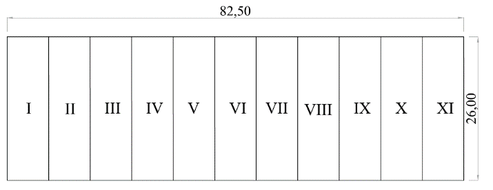 | Figure 2. Geometric scheme of type 6 - 26x82,5m |
Geometric composition of tassels and bracing elementsThe terranes used have a rectangular cross section and were divided into two types.• Tierce "T1": hyper-static beam in both directions, with end restraints on the French hands, and internal support on the lattice knots, according to Figure 3;• Tierce "T2": isostatic beam with respect to the x-axis, supported on the French hands, and hyperestatic behavior with respect to the y-axis, with end restraints on the French hands, and internal support composed of chain lines, located in the middle of the gap).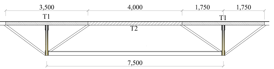 | Figure 3. Tierces nomenclature |
The bracing system is composed of: terranes and steel cables with tensioners, arranged in the plane of the upper flange and in the plane of the lower flanges in the shape of "T" beams (table of 2,5x15cm, web of 2,5x15cm) locked transversely in the midpoint (7x7m pieces). The contravened regions of each shed are represented below, following the geometric scheme of Figure 2.• Type 1: bracing in regions I, IV and VII;• Type 2: bracing in regions I, IV, V and VIII;• Type 3: bracing in regions I, IV, V and VII;• Type 4: bracing in regions I, IV, VI and IX;• Type 5: bracing in regions I, IV, VII and X;• Type 6: bracing in regions I, IV, VII and XI.Determination of actionsAs actions in the structures, permanent actions (structural and non-structural) and a variable (loads due to wind) were considered. For the determination of actions in the structures, all normative descriptions proposed by NBR 7190:1997 [9] and NBR 6120:1980 [10] were followed. In order to determine the wind action, NBR 6123:1988 [11] was used.For the calculation of the weight of the structure, the entire geometric composition of the structures was considered, and C-20 strength class wood was used for all spans. At the entrance, wood was used class C-30 and for the bracing class C-20. The weight of the steel tile (non-structural permanent action) was 0,05kN/m².Following the requirements of NBR 6123:1988 [11], the following parameters were defined for the variable actions: characteristic wind velocity for the Sinop-MT region, which are located the project buildings of 30m/s; factor S1 referring to the roughness and topography of the terrain, which has the value equal to 1 for flat regions; factor S2, which depends on the geometric characteristic of the building and varies according to each study span (16 to 26 meters); and factor S3 corresponding to the occupancy rate of the building equal to 1. The internal and external pressure coefficients for each geometric configuration were also defined based on this standard. With all the parameters combined with the external and internal coefficients, the dynamic wind pressure was calculated for further calculation of the actions in the structures.In order to carry out the combinations of actions in the structure, the following recommendations were followed: NBR 8681:2003 [12] and NBR 7190:1997 [9]. Considering the Ultimate Limit State with last normal combinations and the State Service Limit with long duration combinations, the latter used to calculate the displacements of the structures.Dimensioning of structural elementsFollowing the requirements of NBR 7190:1997 [9], the dimensioning of the structural elements as well as the connections between these elements was carried out. According to the standard, structural elements with a slenderness of less than 40 should be made traction checks and normal and parallel compression to the fibers. For medium-slender pieces, with slenderness between 40 and 140, one must also verify the stability. For the third, elements subject to oblique flexion, verification must be made for simple oblique flexion.Also, according to the norm, when it comes to the calculation of the connections, two factors are considered: the bending of the pin or the inlay of the wood (this can be parallel, normal or inclined to the fibers). In this work, screws were used as connecting elements.After the sizing of all structural elements, a comparison was made between the initial estimate and the actual design situation for each structure. According to the regulations, a difference greater than 10% implies that the own weight must be recalculated.Quantification of materials and construction of graphsAfter sizing, the results were organized into tables and graphs, which express the volumetric consumption of wood per area built for each proposed project situation, as well as the number of pins used throughout the structure.
3. Results and Discussion
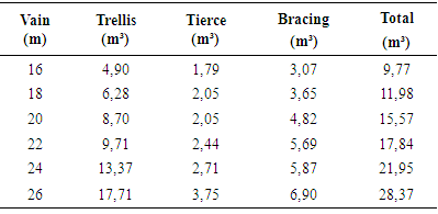
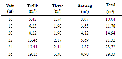
Volume of woodIn order to ensure efficient sizing, taking into consideration technical and constructive aspects, each truss rod and other components were dimensioned separately.The following are the results of the volumetric consumption for each structural element and the total for each proposed project typology.Table 2. Volumetric consumption in m³ for all elements of the open shed
 |
| |
|
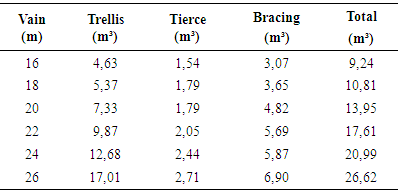
Table 3. Volumetric consumption in m³ for all elements of shed 6:1
 |
| |
|
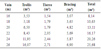
Table 4. Volumetric consumption in m³ for all elements of the 2:1 shed
 |
| |
|
Table 5. Volumetric consumption in m³ for all elements of the 1:1 shed
 |
| |
|
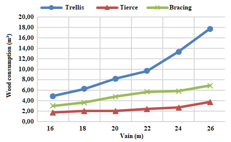 | Figure 4. Total wood consumption (m³ for open ratio - Open) |
It can be seen in all the opening relationships that, as the size of the span increases, the volume of wood in the lattice also increases almost exponentially. This is due to the fact that the larger the span, the greater the area of wind loading on the lattice, which will consequently result in greater internal stresses on the elements. When it comes to the open ratio, the 6:1 ratio, in which the wind action has more critical pressure coefficients due to the difference in air mass penetration in the shed faces, the stresses generated by this opening ratio would be the most high of all the projects carried out in this work, being one of the typologies of the project that presented the highest volumetric consumption of wood, being, in some cases, behind only the fully open coverage. The third one, being the structural element responsible for transferring the forces from the wind to the trellis, also has its consumption varied according to the type of opening, in the same way as the trellis.The bracing system, however, does not change its consumption directly linked to the wind action, but rather to the number of elements that compose this system.Consumption of wood per square meter of constructionThe results of the volumetric wood consumption ratio for the planted area of all 24 projects, being six types of spans and four types of openings, are represented in figures 5 to 8.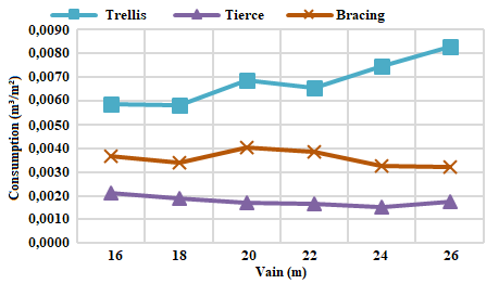 | Figure 5. Wood consumption in m³/m² for open ratio – Open |
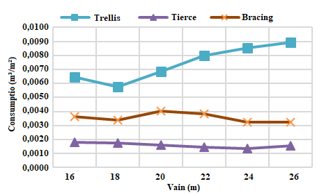 | Figure 6. Consumption of wood m³/m² for opening ratio - 6:1 |
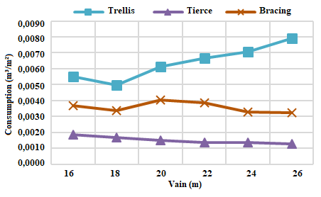 | Figure 7. Consumption of wood m³/m² for the opening ratio - 2:1 |
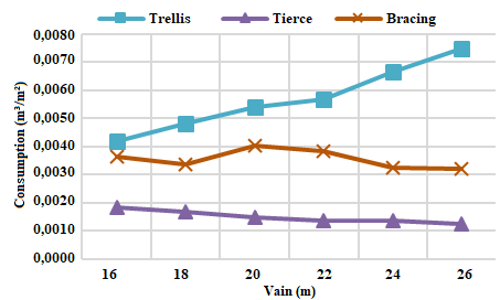 | Figure 8. Consumption of wood m³/m² for the opening ratio - 1:1 |
It is noticed that the relation of consumption to the third one has a slight reduction as the gap increases. This fact is due to the increase of area in plan, where even varying the spans, the spacing between trusses of 7,5 meters is maintained constant, and also maintaining the ratio in plan of the building of 1:3.Figure 6 shows that the bracing has a peak of consumption in the span of 20 meters and that soon after that consumption reduces. The explanation for this is given by the fact that the spans 20 meters and 22 meters have the same number of sections contraband, as well as the same number of elements of bracing, however, the building with span of 20 meters has smaller area, which results in a material ratio per larger square meter.The increase in the material consumption ratio per square meter for trusses is due to the fact that the larger the gap between supports, the greater the number of structural elements needed to overcome the gap. Apart from the increase in the number of structural elements, there is also the more intense wind action over larger coverage planes, this intense action, added to the permanent load increase, generates significant efforts in the structure, requiring more robust parts to able to withstand such load.The 1:1 aperture ratio proved to be the most economical at all apertures. The justification for this may be the low-pressure coefficient that the wind has in buildings with this opening ratio. With a low coefficient, the internally generated stresses are lower, allowing the use of less slender parts.Analysis of total volumetric consumptionThe comparative analysis between the total spans consumption for each opening was performed according to the graph below: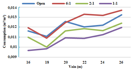 | Figure 9. Total consumption m³/m² for all openings |
It is observed that the opening 6:1 was the one that presented the highest consumption, in most cases, between the three opening relationships, losing only to the open building in some cases. Such consumption is explained by the possibility that when the windward face coincides with the side of the main opening, it will allow the entrance of an air mass six times larger than the other air masses entering the building by the other openings, thus causing an increase in the internal pressure coefficient in order to contribute with possible external suction.Following the points of the relation of consumption to the open building, it is observed that to construct an isolated cover, totally open, the most economical of material is 18 meters, presenting the lowest ratio of consumption per meter, as demonstrated in Figure 9.As previously mentioned, the relation with the highest consumption is 6:1, in which the wind has the highest-pressure coefficients, generating considerable effort to the structural elements.Links: Constructive detail and quantificationFor the dimensioning of the connections, it was considered that the junction between diagonals and flanges would be made in the same plane with metal plates, thus allowing the adoption of "I" and "H" profiles. The diameter of the pin is 1,25cm, obeying the restrictions of item 8.3.4 of ABNT NBR 7190: 1997 [9], in which limit the diameter of the pin to be used should be less than or equal to half the thickness (t) of the main part. Also, according to the standard, in item 10.2.4, it restricts the minimum thickness of the steel plate for connection being 6mm.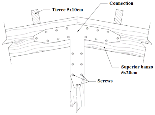 | Figure 10. Boundary-Banzo connection detail (26-meter span 26 knot for 1:1 aperture type) |
For the positioning of the bolts in the connection system, the descriptions of item 8.6 of ABNT NBR 7190:1997 [9], which describes the minimum spacing between the bolts and the outer edges of the parts (Figure 11), were followed.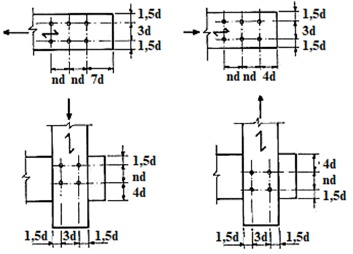 | Figure 11. Screws detail on wooden parts (Source: ABNT NBR 7190: 1997 [9]) |
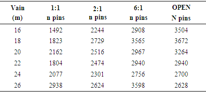
The three main factors that influence the number of pins used in each lattice are the number of nodes and elements to be interconnected, the stress generated by each element and the pin diameter that depends directly on the connected elements thickness. In all connections, pins with a diameter of 1,25cm were used.The total number of screws needed to make the trusses is shown in Table 6:Table 6. Total number of pins required for each project
 |
| |
|
In all cases of connection, the most critical situation was found in the wood.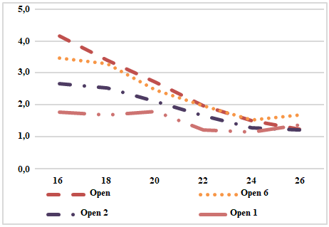 | Figure 12. Pin consumption / m² of construction |
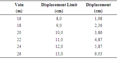
By analyzing the results, it can be seen that the 1:1 opening ratio is the one with the lowest pin consumption per square meter of construction, and as the opening ratio increases, the number of pins required for each meter of construction increases.DisplacementsThe displacement limit for the timber structure is defined by the expression L/200 and only the load with permanent, structural and non-structural loads, according to ABNT NBR 7190.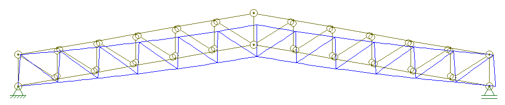 | Figure 13. Example of displacement for Howe trellis, with slope of 10° and span of 16 meters |
Table 7. Relation of arrows to each span
 |
| |
|
4. Conclusions
In view of the results presented in this work, it is concluded that the technical feasibility of the use of C-20 and C-30 hardwood species as structural elements for hedging using parallel Howe bundles with a slope of 10° and spans ranging from 16 to 26 meters.It is also possible to verify the real importance of the elaboration of structural projects for covering, where for the same geometric characteristics, varying only the opening ratio in the main faces, different wood consumption per square meter of building was obtained, also highlighting how much relevant to wind action in roofing structures, as well as the risk of not taking into account the types of opening, in which a simple change in these openings can lead to changes in internal forces in the structural elements, which can lead to ruin the coverage if it is not prepared for such a request.With the use of alternative wood species, which are rarely used for structural purposes, in addition to trying to cheapen the cost of the structure, it is expected to reduce the waste of this material giving it a nobler and not only temporary use, as is commonly done, for the manufacture of boxes.The final result of the volumetric consumption of wood per meter of building was very efficient and satisfactory, ranging from 0,010 to 0,0189 m³/m².
ACKNOWLEDGMENTS
I thank God first, creator and source of life, for the knowledge and wisdom, strength and spirit, grace and rest I have been granted.My family, especially my mother, Lilian Alves da Luz, my stepfather, Lucimar da Silva Carvalho, and my uncles, Enilda Vilalva Ferreira, Adeir João Ferreira, Zurma Vilalva de Miranda and Neraldo Pinto de Miranda, for moral support and for all the opportunities they gave me to get where I am.My girlfriend, Crislaine Pereira da Silva, for being by my side during all the time of this work giving me support, encouragement and always motivating me to move on.To my friends and colleagues who have been with me along this path.To my supervisor, Prof. Dr. Roberto Vasconcelos Pinheiro, for the trust and indispensable guidance to carry out this study.To the University of the State of Mato Grosso, for making possible the learning during all those years, and to all the teachers of the campus of Sinop - MT.
References
| [1] | Medeiros, R. C.; Arroyo, F. N.; Almeida, D. H.; Almeida, T. H.; Christoforo, A. L.; Lahr, F. A. R. Forces in Bracing Elements of Timber Trusses. International Journal of Construction Engineering and Management, v. 7, p. 29-34, 2018. |
| [2] | Paludo, D. F.; Pinheiro, R. V.; Arroyo, F. N.; Almeida, T. H.; Almeida, D. H.; Christoforo, A. L.; Lahr, F. A. R. Timber Use in Truss Structures for Roof (-Howe- Type - 8 to 18 Meters). International Journal of Materials Engineering, v. 7, p. 93-99, 2017. |
| [3] | Partel, H. Sistema informatizado para projetos de estruturas industrializadas de madeira para telhado. São Carlos: Escola de Engenharia de São Carlos, 2000. |
| [4] | Pfeil, W.; Pfeil, M. ESTRUTURA DE MADEIRA. 6ª. ed. Rio de Janeiro: LTC, 2003. |
| [5] | Christoforo, A. L.; Arroyo, F. N.; Lopes, D. A.; Panzera, T. H.; Lahr, F. A. R. Full Characterization of Calycophyllum Multiflorum Wood Specie. Engenharia Agricola, v. 37, p. 637-643, 2017. |
| [6] | Andrade Junior, J. R.; Lahr, R. A. R. Avaliação das estruturas de cobertura em madeira de um galpão de estoque de produtos químicos. Ambiente Construído, Porto Alegre, v. 14, n. 3, p. 75-85, jul./set. 2014. |
| [7] | Pinheiro, R. V.; Influência da preservação contra a demanda biológica em propriedades de resistência e de elasticidade da madeira. Tese (Doutorado). São Carlos: Escola de Engenharia de São Carlos, Universidade de São Paulo, 2001. |
| [8] | Calil Neto, C.; Ligações com parafusos auto-atarraxantes sem pré-furação para uso em estruturas de madeira. Tese (Doutorado). São Carlos: Escola de Engenharia de São Carlos, Universidade de São Paulo, 2014. |
| [9] | Associação Brasileira De Normas Técnicas. NBR 7190 - Projeto de estrutura de madeira. Rio de Janeiro, 1997. 50p. |
| [10] | Associação Brasileira De Normas Técnicas. NBR 6120 - Cargas para cálculo de estruturas de edificação. Rio de Janeiro, 1980. 6p. |
| [11] | Associação Brasileira De Normas Técnicas. NBR 6123 - Forças devidas ao vento em edificações. Rio de Janeiro, 1988. |
| [12] | Associação Brasileira De Normas Técnicas. NBR 8681 - Ações e segurança nas estruturas. Rio de Janeiro, 2003. 15p. |
| [13] | Calil Junior, C. et al.; Dimensionamento de Elementos Estruturais de Madeira. Barueri, SP: Manole, 2003. 149p. |
| [14] | Calil Junior, C.; Molina, J. C.; Coberturas em estruturas de madeira: exemplos de cálculo. 1 ª ed. São Paulo: Pini, 2010. 214p. |
| [15] | Szücs, C. A. et al.; Estruturas de Madeira. Departamento de Engenharia Civil. Universidade Federal de Santa Catarina. Florianópolis, 2015. 219p. |
| [16] | Rocco Lahr, F. A. et al.; Avaliação das estruturas de cobertura em madeira de um galpão de estoque de produtos químicos. São Paulo, 2013. |
| [17] | Ribeiro, A. C. S.; Estudo comparativo do consumo de madeira em estrutura com telhado de concreto, entre a tecnologia corrente e a preconizada pela NBR 7190:1997. Projeto de pesquisa. Universidade do Estado de Mato Grosso, Sinop, 2014. |
| [18] | Gesualdo, F. A. R.; Estruturas de Madeira (Notas de Aula). Apostila para a faculdade de Engenharia Civil. Universidade Federal de Uberlândia. 2003. 92p. |
| [19] | Paludo, D. F. Pinheiro, R. V.; Emprego de madeiras em estruturas treliçadas para cobertura. Universidade Federal De Mato Grosso, 4° Encontro de Edificações e Ambiental, 2016. |
| [20] | Cavalheiro, R. S. et al. Mechanical Proprieties of Paricá Wood Using Structural Members and Clear Specimens. International Journal of Materials Engineering, junho 2016. P. 56-59. |
| [21] | Tomczyk, O. F.; Dimensionamento de treliças de madeira para coberturas a partir de critérios técnicos comparado a métodos empíricos (estudo de caso). Centro universitário de união da vitória, União da Vitória, 2010. |
| [22] | Pinheiro, R. V.; Lázaro, L. G. F.; Repair Methods Indication for a Timber Coverage Structure Located in Sinop City - Brazil. International Journal of Materials Engineering, v.2, n.6, p. 39-46, Scientific & Academic Publishing, 2016. |
| [23] | Carnielle, R. O. A. Caracterização das construções com madeira em Uberlândia, patologias, projetos e detalhes. Universidade Federal de Uberlândia. Uberlândia, p. 144. 2011. |
| [24] | Pinheiro, R. V. et al.; Repair Methods Indication for a Timber Coverage Structure Located in Sinop City - Brazil. International Journal of Materials Engineering, v.2, n.6, p. 39-46, Scientific & Academic Publishing, 2016. |
| [25] | Zanini, H. M.; Vito, M. Dimensionamento e levantamento de custos de uma treliça de madeira em cobertura de pavilhões utilizando como parâmetro uma treliça metálica. UNESC - Universidade do Extremo Sul Catarinense, 2011. |
| [26] | Miotto, J. L.; Junior, C. N.; Estudo comparativo entre sistemas treliçados para cobertura em estrutura de madeira. Universidade Estadual de Maringá, Maringá, 2015. |
| [27] | Garcia, D. R. J.; Leão, É. B.; Pinheiro, R. V.; Madeiras alternativas em arcos treliçados, para passarelas de pedestres. Universidade do Estado de Mato Grosso, Sinop, 2015. |
| [28] | Skog, K. E.; Wegner, T. H. Et Al. Desirable properties of wood for sustainable development in the twenty-first century. Annals of Forest Science. France, v. 72, n. 6, p. 671-678, 2015. ISSN 1286-4560. |

 Abstract
 Reference
 Full-Text PDF
 Full-text HTML