-
Paper Information
- Next Paper
- Paper Submission
-
Journal Information
- About This Journal
- Editorial Board
- Current Issue
- Archive
- Author Guidelines
- Contact Us
International Journal of Materials Engineering
p-ISSN: 2166-5389 e-ISSN: 2166-5400
2018; 8(5): 120-127
doi:10.5923/j.ijme.20180805.06

Proof Load Test on Bridges and Viaducts: A Bibliography Analysis
 Abstract
 Reference
 Full-Text PDF
 Full-text HTML
Eduardo Chahud1, Vinicius Borges de Moura Aquino2, Diego Henriqu de Almeida2, André Luis Christoforo2, Francisco Antonio Rocco Lahr3
1Department of Civil Engineering, Federal University of Minas Gerais (UFMG), Belo Horizonte, Brazil
2Centre for Innovation and Technology in Composites – CITeC, Department of Civil Engineering (DECiv), Federal University of São Carlos, São Carlos, Brazil
3Department of Structural Engineering (SET), University of Sao Paulo, São Carlos, Brazil
Correspondence to: André Luis Christoforo, Centre for Innovation and Technology in Composites – CITeC, Department of Civil Engineering (DECiv), Federal University of São Carlos, São Carlos, Brazil.
| Email: |  |
Copyright © 2018 The Author(s). Published by Scientific & Academic Publishing.
This work is licensed under the Creative Commons Attribution International License (CC BY).
http://creativecommons.org/licenses/by/4.0/

This article aims at the study of proof load tests on bridges and viaducts, presenting the definitions and methods related to this test, in addition to describing the first load tests ever performed in Brazil. It evaluates the procedures of the Brazilian standards (NBR 9607:2013), comparing with the international regulations. The following topics present the importance and the way in which the load test is carried out, showing the risks of this test. Finally, this article explains the relevance of instrumentation and describes the most commonly used equipment: extensometer, inductive displacement transducer, deflectometer, clinometer, topography instruments, single-cell cell for measuring stationary forces and hydrostatic leveling system with pressure cell.
Keywords: Proof load test. Bridges. Instrumentation
Cite this paper: Eduardo Chahud, Vinicius Borges de Moura Aquino, Diego Henriqu de Almeida, André Luis Christoforo, Francisco Antonio Rocco Lahr, Proof Load Test on Bridges and Viaducts: A Bibliography Analysis, International Journal of Materials Engineering , Vol. 8 No. 5, 2018, pp. 120-127. doi: 10.5923/j.ijme.20180805.06.
Article Outline
1. Introduction
- It has been verified a great degradation on bridges and viaducts along previous years due to pathological manifestations associated to its use or its environment. On 1940 decade, Rocha [1] related the load increase provided by road and railway development in Brazil. Palazzo, Santos Filho and Moreira [2] add the fact that road bridges are on aging process with serious deterioration, demanding strength verification motivated by new load values imposed by traffic rise and, also, lack of a maintenance policy, which leads to reforms or early replacement of these structures. Facing the exposed, it is observed the need of bridges and viaducts load capacity verification. Proof load test is a very efficient test to analyze the stability of a concluded construction, once it is analyzed the structural behavior on service conditions. Besides, Oliveira [3] recommends this test should be done on new structures, serving as a parameter for structures acceptance.This study will treat the proof load test on bridges and viaducts, focusing on concepts, procedures and instrumentation related to the test. It will also analyze procedures referent to proof load test standardized by Brazilian and international standards.
2. First Proof Load Tests in Brazil
- Formerly bridge monitoring and testing were characterized by observation process of structural behavior, techniques conceptions and appropriate equipments. At this time, calculus methods were reduced, being common the use of simplified models for complex structures analysis. With these conditions, the information obtained through monitoring was more relevant for safety verification [4].According Lacerda et al. [5], the first proof load tests in Brazil occurred on 1930 decade and they were executed in foundations, bridges and viaducts. It is highlighted, on this time, proof load test on São Vicente Pensile Bridge (1936), Victor Kondere and Lindoia Bridges (1930 decade) and Ernesto Dornelles Bridge (1944). In these works of art were executed static proof load tests aiming to evaluate strength capacity of the bridge for vehicles passage, with the first proof load test in Brazil was made by IPT (Technological Research Institute), under orientation of engineer Telêmaco Van Langendonck in 1936. In 1974, before Rio Niterói Bridge opening, a proof load test was performed, gathering several loaded trucks (Figure 1).
 | Figure 1. Proof Load Test on Rio-Niterói Bridge. (Source: Arquivo O Globo (1974)) |
3. Definition of Proof Load Test
- The proof load test on bridges intend to verify resistant capacity of a structure for major loads, demonstrate the possibility of a eventual load increase per truck axle or present structure capacity to resist load on service conditions, enabling evaluate if the structure is in condition to used according the degree of safety predicted on construction phases.According Brazilian Standard ABNT NBR 9607 [6], proof load test is defined as a set of activities destined to evaluate structure performance through measure and control effects caused by external loads application.On Montoya et al. concept [7], proof load test is structure monitoring to observe its actual state and real load capacity aiming to guarantee a high level quality on service. This type of test should occur by systematic application of monitoring techniques, and by high capacitated team able to perform the structure maintenance and monitoring activities and results interpretation, reducing, then, the corrective maintenance.
4. Proof Load Test Utilization
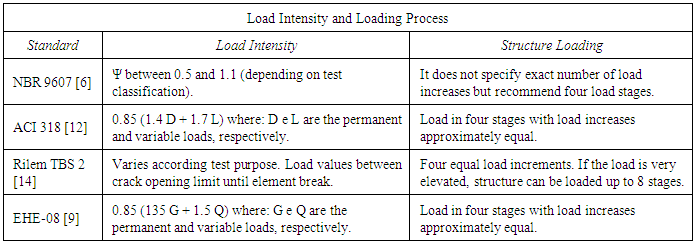
- After a reinforced concrete bridge conclusion, one of main verification which should be done is the proof load test, especially if there are doubts about its resistant capacity, identification of interferences caused by quality of used materials on construction or when the utilization is different from the predicted on initial conception of the structure. For constructions already built, proof load test is recommended for structure stability evaluation when it is realized the lack of maintenance, alteration of its use and emergence of pathological manifestations.In this way Oliveira and Junior [8] recommends the proof load test, a more efficient load test, to verify the safety of a construction already concluded. Still, according the authors, load tests are not always made in Brazil, due to the fact if reinforced concrete structures are made according the design and used materials were approved on quality control tests, it is admitted the automatic acceptance of the structure. For road constructions, the same criteria relative to material quality are used, performing, at the same time, a verification on structural design.With a distinct view, for constructions the structure behavior must be proved, in the case of bridges, the Spanish Standard EHE-08 [9] indicates the need of a proof load test aiming structural safety, classifying this type of test as regulatory proof load test. In this context, different from the disposed on Standard ABNT NBR 9607 [6], it can be inferred the importance of demanding on public use constructions, such as bridges and viaducts, a proof load test for its acceptance, with demonstrated structure capacity, on service conditions, support loads predicted on design, freeing users and structure of possible risks during its use.In the case of existent road construction, Oliveira [3] highlight that exist situations that structures, such as bridges and viaducts, can be submitted to loads above the predicted on design, being indispensable the evaluation of a proof load test to analyze the structure and avoid its failure. The author also suggest that, on new constructions, the proof load test and only after the analysis of results, the construction would be accepted or not, whereas in these cases, the proof load test must verify the static and dynamic behavior of constructions, and gauge structure strength under load.On proof load tests, it should be applied specific loads on the structure to identify which is the maximum supported capacity on elastic regime. The test must be previously planned and the loads used in the tests must be applied on increments, performing the bridge monitoring to predict possible non linear behavior. Load tests must be accompanied by experienced professionals for not submit the structure to loads that causes deformations beyond the elastic regime. The test must stop when observe signs which may cause damages to the structure or reach the load predetermined on test beginning [10].There are two types of load test: static load test which is based on structure behavior observation under static load, and the dynamic load test, which consists, basically, on structure vibration and the observation when vibrated. One of the best procedure to evaluate safety conditions on existent bridges is the static load test.To check the static behavior of bridges and viaducts, load should travel on the structure and at determinate points, it must stagnate, on enough time interval, to measure the provoked displacements. To verify the dynamic behavior of the structure, it must be studied the impact effects and longitudinal forces that appears on bridges and viaducts, due braking. These verifications are based on relations of deformations between the load on movement and load stagnated.On dynamic load test, inertial effects can be considered, once loads are applied quickly. In this type of test, it can be easily observe stresses, displacements, strains and accelerations during vehicle traveling on the bridge, independently of vehicle velocity, due to use of equipment which register these data. On the other hand, on static load test, loads are applied slowly, which allows to despise inertial effects. In this type of load test, it can be easy observed stresses, displacements and deformations when loads or vehicles are stopped on the analyzed bridge.Dynamic tests enables evaluate experimentally the dynamic characteristics of a structure, which can observe the frequency, vibration mode and damping coefficients. When it is desired to evaluate wind and traffic loads, it is common to use this vibration test on free regime [4].Considering Oliveira [3], another form to achieve these tests, in cases of bridges with large spans and unusual structures which does not accomplish design specifications relative to repetitive loads, is producing short term oscillations, permitting to determine the vibration period under load.
5. Proof Load Test Realization
- In Brazil, there are few specialized companies which displays the conditions to perform load tests on bridges. The purpose of a load test is to identify values of displacements, deformations, stresses and efforts acting on the structure. Actually this type of test comprises load application to evaluate structure stability using generally additional load of several materials, such as: water, sand, cement, vehicles or load application by hydraulic instruments.When evaluating a proof load test, it is important submit the structure to a load in a manner to enable this structure behave as if it is on service conditions. This test destines to prove the good execution of constructions and check if it behaves according the disposed on the project, guarantying its functionality.Proof load tests on bridges are performed by load increments on structures, aiming to gauge the maximum load quantity the structure support without damages and failure. Despite the risk if load increment provoke irreversible damages and displacements, during load test it must be established evaluation criteria and monitoring, also the structure behavior supervise. This type of test is the most recommended on use change and increase load prediction, once it evaluate the structure behavior during load increase and, being well done, enables to obtain the best diagnosis of structure strength. Realizing the demand of structure rehabilitation to support predicted load increases, the structure must undergo into another load test after rehabilitation.
6. Structures Analysis Techniques on Proof Load Test
- Construction science promotes studies and constructive practices which should be analyzed by experimental principles, enabling gauge and test obtained results on structure construction execution, verifying if the predicted on design was demonstrated during and after constructions conclusion. It is important to evaluate values that can be calculated and proved to guarantee structure and users integrity. Theories and constructive techniques confirmation must be confirmed and analyzed through instrumentation.Advances on structures analysis techniques and modern instrumentation gadgets allows, even more, the success of load tests. Techniques and instrumentation used on load tests will be treated in this study after.Displacements can be measured directly by displacement gauge, being mechanic (deflectometers or comparing clock) or electronic (displacement transducer). Strain can be gauged directly by the use of extensometers and, based on strain measures, it is possible to determine stress and intern efforts on determined section of structural element.With automation, benefits arose which led to progressive use of sensors that allow automatic measures to the detriment of others. It is noticeable the great increase on obtained data with automatic measures, providing a major knowledge about constructions behavior [4].On monitoring evaluated with tests, instrumentation and load test it is possible to observe if a bridge structure in on the end of its lifespan and if there is the demand of any interference to reinforce or recover and even determine the need of a detailed monitoring to ensure its stability and safety.In this sense, Montoya et al. [7] emphasize with the monitoring results a better understanding about the real behavior of the structure, contributing for adequate design elaboration of the reinforce. Besides, studies indicated the demand of measures to reduce the dynamic amplification factor, being one of them, the decrease on loaded composition velocity, when traveling on the bridge. Identifying anomalies or fails, the analysis and punctual studies should be proceeded to evaluate elements lifespan.
7. Risks on Proof Load Test Performance on Bridges and Viaducts
- Proof Load Test on bridges provides an elevated risk on damaging the structure. By this reason, this test is avoided if there are no preliminary studies and other simplified evaluation, such as monitoring and non destructive tests. Performing a load test, structure and users safety must be preserved, stopping the traffic and predict the possible damages which could be provoked during test realization.Due to this situation, it must be observed the real need of this test. Conform Carbalho [11], this type of test should not be done if preliminary studies indicates that it is unlikely the test reveals a load capacity superior the demanded for the bridge, if the associated cost to the test evaluation is equal or exceed the structure reinforcement cost, it the structure is not capable to support the minimum test load and, when traffic conditions on the structure become the load test impractical.
8. Normalization
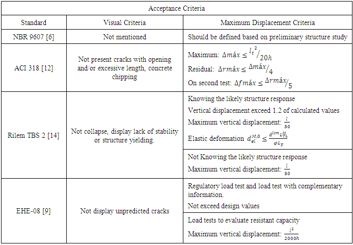
- According Oliveira [3], the main international regulation for load test on reinforced concrete structures are the American Standard ACI 318 [12], Australian Code AS 3600 [13], Spanish recommendation [9], European Recommendation RILEM TBS [14] and, in Brazil, Brazilian Code ABNT NBR 9607 [6].It is important highlight that each code has its particularities, but all displays some similarities. It occurs due to the fact that standards are based on consecrated methods, scientific studies and precedent practices. For example, Brazilian Standard and European recommendation are unlinked from designing standard [3]. The other standards are integrant part of normative set which rules reinforced concrete designing. On the other side, all standards displays acceptance criteria based on visual aspects or element deflection.In Brazil, the most common load test are the foundation stake load test. It happens due to Brazilian Standard NBR 6122 [15], on its item 9.2.2 obligates static load test for acceptance of foundation stakes. Brazilian Code NBR 9607 [6] recommends load test for cases of: structure acceptance, changes on structure utilization, constructive phases which lead to exceptional load in part of the structure, after accidents or anomalies observed during construction or structure lifespan, total or partial lack of designed elements, constructive conditions and structure behavior study unfamiliarity.Brazilian Standard NBR 9607 [6] presents an activities flow chart which should be done on load test execution, conform Figure 2. The main points to be analyzed are the initial study of structure characteristics for loads definition and acceptance criteria and stage accompanying through structure instrumentation to guarantee structure integrity during the test.
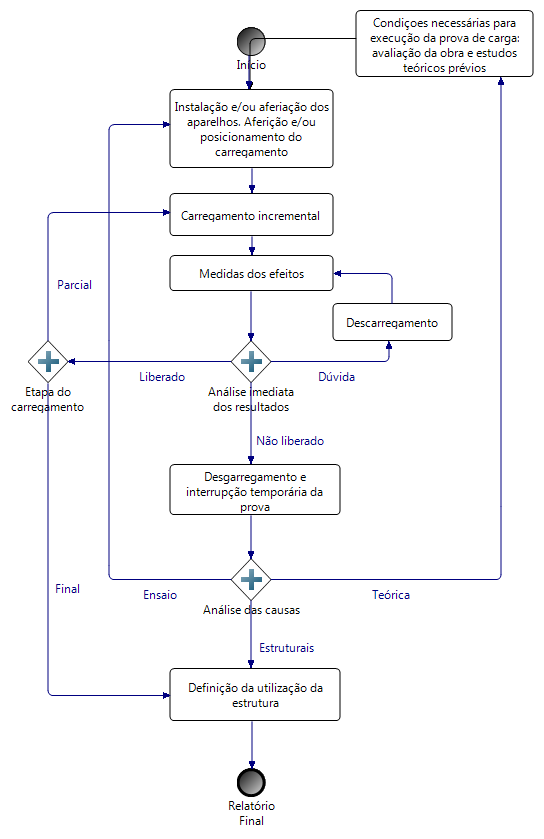 | Figure 2. Control Activities Flow Chart of a Load Test. (Source: Brazilian Standard ABNT NBR 9607 [6]) |
|
|
9. Instrumentation
- The manner how data is collected during load tests on bridges an viaducts is extremely important. For such, instruments utilized must be designed according their purposes, precision, sensibility and pre established quantity on predicted theory studies phase. On the same way, technical workforce dimensioning must guarantee quickness and confidence on several operations performed.Gonçalves, Takeya and Abrahão [16] reaffirm the success of a load test is directly related to the measure equipment choice compatible to the expected responses, i.e., the adequate sensibility, on technical capacity and work equip training responsible by its utilization.The types of utilized instruments for measures depend on test purpose, project conditions and which variables will be monitored. Most of cases, on static load test, the main equipments are the strain gauge, vertical displacement gauge and angular strain gauge [3]. In this sense, Oliveira and Junior [8] highlight the instruments used for strain and deformation measures caused by loads are based on mechanical, electrical and optical principles. The most used are the extensometers, deflectors and clinometers. Actually, optical fiber sensors also has been used and topographic instrumentation, such as total station, and digital laser level, are efficient on data gathering.Next, usually used equipments are presented:
9.1. Extensometers
- These are gadgets capable to measure strain, by electrical resistance or mechanically. According Oliveira [3], the mechanical extensometer was one of the first to be used and its operation is based on a system of levers and engines to amplify strain. They are utilized for static measures, due they are not appropriate to frequency responses, necessary on dynamic measures.
9.1.1. Electrical Extensometer
- According Gonçalves, Takeya e Abrahão [16], this type of extensometer is the most used. This type of extensometer, when fixed on the element, correlate the strength variation, due its stretching or shortening, with element length variation.
9.1.2. Optical Fiber Extensometer
- For Michie et al. [17], the optical fiber extensometer has the same operation principle of the electrical extensometer, bus instead correlate strength with length variation, it correlates length variation with light losses along its length. In this way, Oliveira [3] point out optical sensors owns the advantage to be immune to corrosion, not presenting detritions.
9.1.3. Acoustic or Vibrant String Extensometer
- Length variation measures are executed by frequency auscultation of a steel wire vibration (vibrant string) extended between two points and connected to the measure basis, with the auscultation made by a electromagnet [18].
9.2. Inductive Displacement Transducer
- Also known by LVDT (Linear Variable-Differential-Transformer), it is composed by inner coils, which has its operation principle associated to a electromagnetic phenomenon generated by alternating current that flows through a coil producing an electromotive force on a next coil [3].On Almeida [19] view, although LVDT transducer operation depends on excitement with alternating current, in market there are transducers which operate with continuum current. This equipment demands an initial gauge before assembling and does not indicate directly the displacement. It utilizes electronic amplification and data conversion such an analogical digital plate.Oliveira [3] affirms the advantages of this equipment is that it could be used for displacement measures on static tests or almost static tests and dynamic tests, coupled to the data system. With no mechanical system of amplification, such as engines and levers, it does not introduce secondary efforts on proof test. Then, it is the most recommended for reduced models investigation.
9.3. Deflectometer
- The deflectometer measure the movement from an ordinary point in relation to a extern fixed reference (linear displacements). There are in the market digital and analogical deflectometers. The analogical consists on several docked engines that are triggered by a small rack intercepted by an axle which follows the movement to be measured. An spring united on this axle maintain a small force to keep a positive contact on the structure. The engine system is connected to a pointer which indicates the axle course on a graduated selector, generally divided in 0.025 mm, varying from 6.25 mm to 150 mm. This equipment is fixed on structural elements that are being tested through supports and it can be easily applied [3].
9.4. Clinometer
- It is used to measure the angle between an inclined plan and horizontal plan or between an inclined line and horizontal plan [3]. Therefore, instead equipments that measures linear strain and displacement, the clinometer gauges angular variations. The clinometer consist on a vertical pendulum system and/or a horizontal level bubble as a reference and a graduated scale that measures the angle of the plan or line in degrees or unevenness percentage.
9.5. Topography Instruments
- According Gonçalves, Takeya and Abrahão [16], topography instruments, such as level, theodolite, total station, are very efficient for displacement measures due its great sensibility, providing measures with great precision.
9.5.1. Total Station
- Total Stations are equipments endowed with intern computer and displays precision up to 2 mm [3]. They are used for length measures and horizontal and vertical angular values.
9.5.2. Digital Level
- Instrument similar to total station, which displays sensibility up to 1 mm, being necessary for level and station use placing targets on the structure called prisms [3].
9.6. Monocordon Cell for Force Measurement on Stations
- Force Measurement on Stations are very important, by reason that it checks structure stability where it is placed. Caeiro [20] explains the monocordon cell test assume every cable are under the same stress, hence, measurement is made in only one cable. Then, it is necessary just multiply the force installed on the cable by the number of cables which compose the station to evaluate the installed force on the station.
9.7. Hydrostatic Leveling System with Pressure Cell
- Hydrostatic leveling system associated to pressure cells, which measures vertical displacements, is based on the communicating vessels principle. According Marecos [21], the circuit is closed and calculates the pressure difference between fixed point, where it is installed a water storage which ensure a constant reference pressure, and the point where it is intended to calculate strain is placed a pressure cell. This system can be influenced by external elements, such as traffic, which can induce vibrations on water in tube, affecting the measurement evaluated by the pressure cell.
10. Final Considerations
- Proof Load Test consist on load application to evaluate structure stability, identifying displacement, stress, strain and acting efforts. It enables analyze structure performance, revealing it there is the need of intervention to reinforce it, ensuring, then, its functionality with safety. This test is indicated for new structures as well as ancient structures.When executing the load test, it is important to attempt for structure safety due to elevated risk the test expose the structure. It should avoid carrying out this test without preliminary studies and with major information, as monitoring and non destructive tests.About normalization, it is important highlight that, when compared with other standards and recommendations, Brazilian Standard NBR 9607 [6] presents several unsatisfactory points. This Code does not specify clearly which should be load increments and not even indicate visual acceptance criteria. American and Spanish standards are clear about procedures and structure acceptance criteria.This research intended to perform an analysis of proof load test application on bridges and viaducts. The execution of this practice is widely beneficial for society and economy, however, Brazilian standard does not demand that bridges and viaducts, which presents high traffic level, must be submitted to proof load test. Such requirement would demonstrate the structure on service conditions resist to applied efforts and minimize possible risks for users during its lifespan.Proof Load Test had already evoluted, mainly on used equipments, ensuring quick and precise results, but, given its importance on engineering, it is necessary to update and complement the normalization and regulation of this test in Brazil.
ACKNOWLEDGEMENTS
- For all the provided support, the authors thanks the Coordenação de Aperfeiçoamento de Nível Superior (CAPES) and the Conselho Nacional de Desenvolvimento Científico e Tecnológico (CNPq).