-
Paper Information
- Next Paper
- Paper Submission
-
Journal Information
- About This Journal
- Editorial Board
- Current Issue
- Archive
- Author Guidelines
- Contact Us
International Journal of Materials Engineering
p-ISSN: 2166-5389 e-ISSN: 2166-5400
2018; 8(4): 59-65
doi:10.5923/j.ijme.20180804.01

Determination of the Sliding Modulus and Limit Strength of Shear Connectors for Mixed Wood-Concrete Structures
 Abstract
 Reference
 Full-Text PDF
 Full-text HTML
Júlio C. Pigozzo1, Felipe N. Arroyo2, Diego H. Almeida3, André L. Christoforo3, Carlito Calil Junior4, Francisco Antonio Rocco Lahr4
1Department of Civil Engineering, Technology Center, State University of Maringá (UEM), Maringá, Brazil
2Faculdades Integradas de Cacoal (UNESC), Cacoal, Brazil
3Department of Civil Engineering (DECiv), Federal University of São Carlos (UFSCar), São Carlos, Brazil
4Department of Structural Engineering (SET), São Carlos Engineering School, São Paulo University (EESC/USP), São Carlos, Brazil
Correspondence to: André L. Christoforo, Department of Civil Engineering (DECiv), Federal University of São Carlos (UFSCar), São Carlos, Brazil.
| Email: |  |
Copyright © 2018 The Author(s). Published by Scientific & Academic Publishing.
This work is licensed under the Creative Commons Attribution International License (CC BY).
http://creativecommons.org/licenses/by/4.0/

Tests with specimens are still the most suitable way in order to get to know the mechanical and elastic behavior of shear connectors, which are used in mixed wood-concrete structures. The most used wood-concrete specimens are the symmetrical push-out type models. About the great diversity of connectors, considering type, stiffness, strength value and their position in the structural member, besides other varieties as: spaces between connectors, dimension variation and mechanical and elastic properties of the materials involved, several normative standards suggest that the wood-concrete specimens shall represent the real connection behavior. In Brazil, due to lacking of normative procedures, plenty of wood-concrete specimen models and criteria have been used for the determination of the limit strength and the slip modulus of these connections. In this paper some wood-concrete specimen models are presented, they were suggested in some normative documents and others presented into the international literature and national research. Some procedures are suggested for obtaining the slip modulus and limit strength, representing the real conditions of the connection.
Keywords: Shear connectors, Slip modulus, Connection strength limit, Connection stiffness
Cite this paper: Júlio C. Pigozzo, Felipe N. Arroyo, Diego H. Almeida, André L. Christoforo, Carlito Calil Junior, Francisco Antonio Rocco Lahr, Determination of the Sliding Modulus and Limit Strength of Shear Connectors for Mixed Wood-Concrete Structures, International Journal of Materials Engineering , Vol. 8 No. 4, 2018, pp. 59-65. doi: 10.5923/j.ijme.20180804.01.
Article Outline
1. Introduction
- Mixed structural system of wood and reinforced concrete has been used successfully in the construction of "T" section beams, in slabs for urban and rural bridges and floors. This type of structure consists of a concrete slab connected to structural members of wood in such a way that the parts work together [1].Joint action of wood and concrete in the flexion is developed by the shear connectors and the level of stress transfer between the concrete slab and the wood can be integral or partial, defining a monolithic behavior when there are no relative displacements between these materials or behavior of a composite part when small relative displacements occur. Most connectors transfer stresses in the interface of the materials in a discrete way, although there are also connectors that transfer these efforts in a continuous way, as for example the bonded connections [1].The efficiency of the structural element with composite section is related to the quality of the connection system, since the behavior of the connectors directly affects the distribution of internal forces as well as the deformations of the structure. Many types of connectors are possible for composite structures of wood and concrete. The main characteristics that allow comparisons between them are: the ultimate strength, the slip modulus and the final cost of installation [2].Sliding modulus represents the rigidity of the connection, being obtained by means of direct tests in concrete-wood specimens. By knowing the stiffness of the connection, the amount and spacing between the connectors, one can estimate the effective stiffness of the mixed structural element [3, 4].In Brazil, the lack of standardization for tests of shear connectors for wood-concrete mixed structures has allowed the researchers to adopt different methodologies and formats for the specimens. Although all of these specimens are symmetric push-out type, there are many differences between them. Few studies have been published on mixed wood and concrete structures, and most authors have used nail-type connectors or bolts perpendicular to the interface of the two materials, concentrating predominantly on composite beams with a "T" section.In this work some models of specimens and some procedures used to obtain the sliding modulus and the ultimate strength of the mixed connections, recommended in some normative standards and used in others consulted literature, are presented.
2. Literature Review
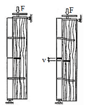
- Structural elements in bending with composite sections formed with the same or different materials, there are several factors that influence the evaluation of the shear forces that occur at the interface of the connected elements, such as: variations and combinations of the internal stresses along the structural element; variations in the mechanical properties of the materials involved; simplifications imposed by the basic assumptions of calculation; approximations used in the calculation models; and the mechanical and elastic behavior of the connections. Thus, the determination of the sliding modulus of the connection from the direct tests on structural elements does not result in values with good precision [5].Testing in specimens is still the best procedure to know the behavior of the connectors, however, as the relative displacements progressively increase, changes in the positions of the support reactions and in the eccentricities of the acting forces occur. In this way, it produces undesirable interferences between the connected members and the behavior of the model gradually progresses to differ from the behavior of the actual connection.The slip modulus is defined as the angular coefficient of the curve obtained from the load versus relative displacement, considering in its value all the elastic and mechanical parameters of the materials involved in the connection, such as: dimensions and stiffness of the connector; stiffness and strength to the inlay of the wood used; if one of the parts is concrete, consider the cracking or crushing strength of the concrete and specimen imperfections [5].Most of the connectors show the load versus relative displacement diagram with nonlinear behavior, and the determination of the secant slip modulus is widely used, simplifying the computational process of the composite structures. The limits of the measurement intervals for determination of the secant slip modulus have been adopted with different criteria, significantly altering the calculated value. Some connectors present large displacements at the beginning of the requests, which then decrease progressively as the connector overcomes the initial gaps in the holes or notches. Other connectors have large displacements, from 40 or 50% of the maximum load that strengths. Considering different behaviors, the procedure definitions for the determination of the secant slip modulus is of fundamental importance. Fig. 1 shows an example of load versus relative displacement diagram and curves whose angular coefficient may correspond to the sliding modulus [6].
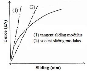 | Figure 1. Sliding modulus obtaining through force versus relative sliding diagram [6] |
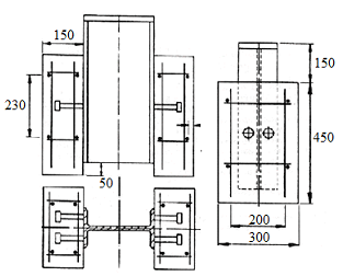 | Figure 2. Shear test specimens for steel and concrete (units in mm) by BS 5400:1979 Standard Code [9] |
3. Specimen Models to Sliding Modulus Determination
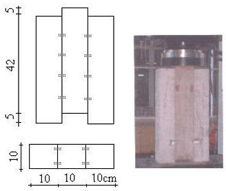
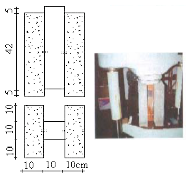
- Several specimen models were used to obtain the ultimate strength and sliding modulus of the connectors. Symmetrical push out shear test specimens are the most commonly used, because they are easy to perform and test.BS 5400:1979 Standard Code [9] (Fig. 2) presents a test specimen for tests of pin-type with heads steel connectors, positioned using welds perpendicular to the shear surface in steel and concrete members (Fig. 2). They observe the details of the double reinforcement with bars of high strength and adhesion, with diameter of 10 mm.Eurocode 4:1994 Standard Code [10] presents a specimen model for tests of pin-type with heads steel connectors, positioned using welds perpendicular to the shear surface in steel and concrete pieces (Fig. 3).
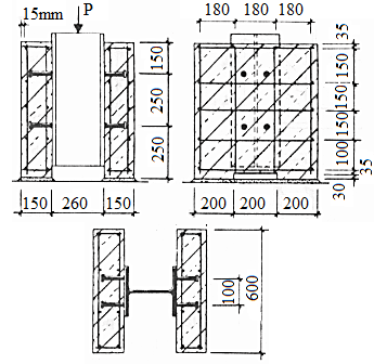 | Figure 3. Shear test samples for steel and concrete (units in mm) by Eurocode 4:1994 Standard Code [10] |
 | Figure 4. Specimen by Richart and Willians [13] (units in cm) |
 | Figure 5. Specimen suggested by Ceccotti [2] |
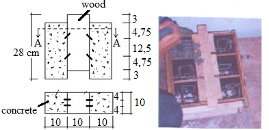
 | Figure 6. Shear specimen for timber and concrete (units in cm) [15] |
 | Figure 7. Specimen by Nicolas [14] (units in cm) |
 | Figure 8. Specimen by Soriano [17] (units in cm) |
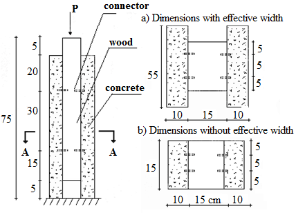
 | Figure 9. Specimen by Matthiesen [18] (units in cm) |
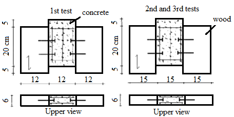
 | Figure 10. Specimen details at the second series of tests [18] (units in cm) |
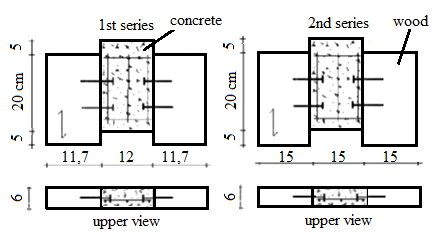
 | Figure 11. Specimen details at the third series of tests [18] (units in cm) |
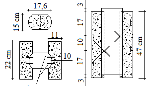 | Figure 12. Wood-concrete specimen steel bar connectors glued in the form “X” [6] (units in cm) |
4. Methods for Sliding Modulus Determination
- There are several proposals in the literature review presenting numerical models, to estimate the sliding modulus values, for connections formed by perpendicular to the shear plane connector in timber connections. Nails, due to their uniformity and low cost, were the most studied connectors in special connectors.For wood-concrete mixed connections, there are no numerical models, considering the variables involved as: the strength and stiffness of the wood; the strength and stiffness of the concrete; and the strength and rigidity of the connector. Specific design conditions, must also be considered, such as: distance between connectors; distance between the connector and the outer edge of the wood or concrete; effects of grouping the connectors; dimensions and formats of special connectors; and the rate and positioning of the reinforcement on the concrete part.Soriano et al. [20] considered in the tests performed the sliding modulus obtained by tangent at the origin of a curve adjusted to the responses of the applied forces versus relative displacements.In order to obtain the sliding modulus of the connection, Matthiesen [18] used a criteria similar to that recommended by the ABNT NBR 7190:1997 Brazilian Standard Code [12], where, through the load versus deformation diagram, it obtained the secant in points 10% and 50% of the maximum strength in each specimen.Matthiesen [18] commented that the force corresponding to 50% of the maximum strength of the connection for some connectors corresponds to a very large relative displacement, significantly reducing the value of the sliding modulus. It suggests the secant passing the limit of 40% of the maximum request.Pigozzo [6] obtained the sliding modulus of the connection using a criteria similar to that recommended by the ABNT NBR 7190:1997 Brazilian Standard Code [12], (C.5 Annex), where, through the load versus deformation diagram, the secant was obtained at points corresponding to 10% and 40% of the maximum strength of the specimen. It obtained the last strength in a similar way to the recommendations given by the same Brazilian Standard Code [12] (Annex C.5; Fig, 13), that is, by secant at points 10% and 40% of the maximum strength and from a parallel line to this secant obtained the limit strength corresponding to the loading that causes the residual deformation of 0.2%. In Fig. 13: L0 = 2∙(7∙d)+a; d = steel connector diameter; a = recommended minimum spacing between connectors; a1 = connector anchorage length on the concrete part; t1 = wood part thickness; t2 = concrete part thickness.
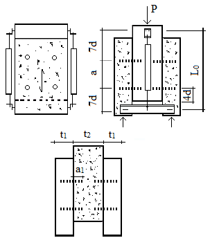 | Figure 13. Base measures L0 or type steel pin connectors [12] |
5. Conclusions
- For mixed wood-concrete composite calculations, the sliding modulus can be assumed as a linear relationship between the applied load and the relative displacement of the connection.Average and characteristic values of the limiting strength and sliding modulus of a connection must be obtained experimentally by specimen that represent the real working conditions of this connection.Specimen must be symmetrical and represent the mixed structure studied. When there are ribs or stiffness, they should be present in the specimens. Dimensions of the parts that make up the specimen must be equivalent to the dimensions of the structure studied.
ACKNOWLEDGMENTS
- Authors thank to Wood and Timber Structures Laboratory (LaMEM), Structural Engineering Department (SET), São Carlos Engineering School (EESC), São Paulo University, by the materials and resources used in this research.