-
Paper Information
- Paper Submission
-
Journal Information
- About This Journal
- Editorial Board
- Current Issue
- Archive
- Author Guidelines
- Contact Us
International Journal of Materials Engineering
p-ISSN: 2166-5389 e-ISSN: 2166-5400
2017; 7(4): 68-76
doi:10.5923/j.ijme.20170704.02

Alternative Woods in Framework Arc for Pedestrian Footbridge
 Abstract
 Reference
 Full-Text PDF
 Full-text HTML
Douglas Rafael Juvenil Garcia1, Érika Borges Leão1, Roberto Vasconcelos Pinheiro1, Diego Henrique de Almeida2, André Luís Christoforo2, Francisco Antonio Rocco Lahr3
1Department of Civil Engineering, University of Mato Grosso State (UNEMAT), Sinop, Brazil
2Department of Civil Engineering (DECiv), Federal University of São Carlos (UFSCar), São Carlos, Brazil
3Department of Structures Engineering (SET), Engineering School of São Carlos (EESC), São Paulo University (USP), São Carlos, Brazil
Correspondence to: André Luís Christoforo, Department of Civil Engineering (DECiv), Federal University of São Carlos (UFSCar), São Carlos, Brazil.
| Email: |  |
Copyright © 2017 Scientific & Academic Publishing. All Rights Reserved.
This work is licensed under the Creative Commons Attribution International License (CC BY).
http://creativecommons.org/licenses/by/4.0/

Uncontrolled and equivocal uses of well-known structural wood species have influenced shortage of these products on market of structural design. In order to raise awareness of the professionals of building construction about alternative wood species, a proposal is here discussed by employing these essences in footbridges. A case study is considered: a hyperestatic trussed arc with intermediate deck, parameters chosen based on local features of structure implementation. This project aims to reduce pressure on traditional species, evidencing alternative woods technical capacity, and improve accessibility in crossings over city streets. To provide greater durability to structure life, preservative treatment type has been set. Finally, by results, that it is possible to apply mean strength wood in large structures, requiring only right combination between structural staticity and wood properties.
Keywords: Woods, Timber structures, Preservative treatment
Cite this paper: Douglas Rafael Juvenil Garcia, Érika Borges Leão, Roberto Vasconcelos Pinheiro, Diego Henrique de Almeida, André Luís Christoforo, Francisco Antonio Rocco Lahr, Alternative Woods in Framework Arc for Pedestrian Footbridge, International Journal of Materials Engineering , Vol. 7 No. 4, 2017, pp. 68-76. doi: 10.5923/j.ijme.20170704.02.
Article Outline
1. Introduction
- Since humanity dawn wood was used as a structural material, such as obstacles transposition, in buildings composing, such as support houses over water (stilt) as well as in war components and personal use items. Historically, its popularity over so many centuries was not weakened, even with different technologies presented in construction field.However, it is common knowledge that abusive forest resources use without sustainable management, causes shortage, even in such abundant material like wood.Particularly, in north-central of Mato Grosso State, there is wood species wide variety, with some highlights from a commercial point of view: Itaúba (Mezilaurus itauba), Angelim (Dinizia excelsa), Cedrinho (Erisma uncinatum), between others. While others do not have same commercial visibility and, thus, are herein referred to as "alternative species," for example: Amescla (Trattinickia sp.), Farinha seca (Lindackeria paraenses), Cajueiro (Anacardium sp.), among others.Injudicious traditional wooden species use in wood market of Sinop (city of Mato Grosso State [MT], Brazil) region, as well as throughout the Amazon Forest region, have brought an obvious lumber shortage, mainly applied to structures. However, as timber regional market has a considerable alternative species amount, arose idea of drawing up a footbridge in truss arc project with intermediate deck, which won a span of approximately 45 meters using such species.As a consequence, it was observed that this work could provide sustainability, principles in the broadest sense of design, i.e, environmental, social and economic.From environmental sustainability, new species dissemination in region aims to demonstrate that there is using various wood types possibility in large structures, since a well-designed technical analysis is performed. Additionally, excessive material consumption and, consequently, pressure deforestation over traditional wood species can be reduced.Regarding social sustainability, this study, demonstrating technical feasibility of alternative species use in construction, primarily in structural elements, sought heating on local and regional market employability, favoring those who develop commercial activity in forestry sector. Furthermore, population accessibility was considered in necessities program.Regarding economic sustainability, it can be imagined that, with alternative species technical feasibility proof, sometimes poorly valued, has an increase in sale added value. Thus, improving life quality of those who work in wood market is also influenced. Finally, it is understood that this study contributes to students and professionals learning in region, on ways to design walkways structures. This fact also promotes quality improvement, in respect to consumption and material costs reduction, to structure durability increase and users safety.Wood construction, being an ecological option, which offers a renewable and durable material abound properly used, with low energy consumption in its production and removing CO2 from atmosphere. Therefore, it is undeniable developing technologies importance for rational wood use, either in structures covers or as transportation problems solution in our cities, mainly because of world urbanization growing process [1].
2. Theoretical Foundation
2.1. Wood
- Wood is a natural material and that has always existed in the environment, has always been available to man. And may be used to meet their basic necessities, such as: production of weapons, shelters, for heating, cooking, lighting, transport (boats), among numerous other purposes.According to Meirelles and Pala [2], eventual wood use at different times in human history varied according to civilizations, Brazil, unlike many Europe regions (Germany, Finland, France), has a strong tradition in clay bricks masonry, brought in its colonization by Portuguese, having a great resistance to buildings constructed in wood. However, by being an abundant material in some country regions, their use in structures is evident.
2.1.1. Preservative Treatment
- Natural defects are related to species types and growth form. Already deteriorative agents can be divided into abiotic agents (mechanical wear, physical degradation, chemical and climate) and biotic (xylophogous beings) [3].Regarding biological deterioration, wood durability depends on anatomical characteristics of each species, being that some species have high natural resistance to biological attack, while others are less resistant [4].Condoms treatments have as target to protect any wooden parts against deterioration actions, whether from natural or physical-chemical phenomena [5].
2.1.2. Properties (Physical, Mechanical and Anatomic / Structural)
- Wood is considered an excellent material, by presenting a considerable mechanical strength and low density, but their mechanical and physical properties have a high variability degree, typically superior to other materials. Must have greater attention about studies in this area. According to Brazilian Technical Norms Association – ABNT NBR 7190:1997 [6], these properties are conditioned by anatomical structure of each species.For dimensioning a structural component, it is essential to consider some properties of wood, such as density, strength, modulus of elasticity and moisture [7].- Physical properties: Physical properties directly influence wood strength performance. According to ABNT NBR 7190:1997 [6]: moisture content; density; dimensional stability (shrinkage and swelling).- Mechanical properties: Mechanical properties are responsible for material mechanical strength, according to requests by external forces. They are divided into elastic and strentgh properties [7].Values to modulus of elasticity are defined depending on the type and direction to the grain, such as: compression and tension parallel to the grain; static bending; compression perpendicular to the grain [7, 8]. According to the ABNT NBR 7190:1997 [6], strength is material ability to withstand stresses. Stress of wood is disposed through the following effects: compression (parallel and perpendicular to the grain), tension, shear, and impact to bending, cracking and hardness.- Natural properties: Natural wood properties can be defined in three classes: organoleptic properties, natural resistance and fire resistance. In accordance with Szücs et al. [4], in principle, wood piece exposed to fire behaves as fuel for flame propagation, but after a few minutes exposed layer is carbonized, resulting in an insulation cover for remainder part.
2.2. Structural Systems
- Just as today, thousands of years ago there was need to overcome obstacles, using a structural system that supported the load weight to be carried by vain. Even being simple, but effective, simply supported beams structural system were used, making structural system in wood the oldest of humanity. With need to traverse larger spans, it was found that plant fibers allow several pieces connection through of rudimentary bindings, making possible creating walkways capable to beat even bigger spans [7, 9].Over time, numerous other structural systems have emerged, enabling creation of true art works. In 1617, for example, it is year that first uses record of a cable-stayed bridge type, where Faustus Verantius presents a structural system that consisted of a timber deck supported by inclined steel bars [10].In accordance with Calil Jr. et al. [7], highway construction or major roads in cities creates enormous cross difficulty to who routes without motor vehicles, requiring construction of reserved passes to these citizens. These passages are called walkways, can be both above and below track.Structural systems employed in construction of wooden walkways are similar to those of other materials and may be of various types, which are described below [7, 9].
2.2.1. Main Structures - Walkway
- - Beams: Very used to achieve small spans where system can be used simply supported beams or continuous beams with intermediate supports. It can be designed as:Ÿ Simple Beams of roundwood;Ÿ Beams of composite roundwood;Ÿ Beams of sawed pieces;Ÿ Beams of composite sawed pieces;Ÿ Beams of glued laminated wood (glulam);Ÿ Beams composed of sawed pieces and plywood.- Plane truss: Structural system used when it is necessary high rigidity and low own weight. There are numerous trusses types, being classified according to stringer, diagonals and vertical pieces. In the wood case, its pieces can be laminated glued, roundwood or sawed.- Plane portico: Structural system recommended for medium spans, whose beam bending moment part is transmitted to pillars, reducing positive momentum in middle of span. The biggest problem of porticos are amendments and connections in angle, where high demands are facing low resistance and stiffness of material and connections.- Arc: Structural system recommended for large spans and, due to its shape, bending effects are reduced, acting basically compression effects. The most commonly used elements are trussed arches of lumber or glued laminated timber (Glulam).- Cable-stayed: Structural system composed by metal cables attached to deck and support poles. Classified according to cables arrangement, in other words, in radial or parallel bundles (range/harp).- Pensile: Structural system composed by deck supported by vertical metallic cables, in turn, are attached to inclined hangers and, these finally transmitting actions to towers.
2.2.2. Secondary Structures – Bracing Structures
- Bracing structures system employed to pieces provide structure a better load distribution, reducing possible vibration problems excess. Furthermore, its use in conjunction with trusses, develop a three-dimensional structural system being able to withstand wind actions and prevent loss of local and global stability, reducing buckling lengths outside trusses vertical planes [11].
2.3. Normatization
- For timber walkways dimensioning, consult following normative documents are essential:Ÿ ABNT NBR 7188:2013: Road and pedestrian live load on bridges, viaducts, footbridges and other structures [12];Ÿ ABNT NBR 6123:1988: Forces due to wind on buildings [13];Ÿ ABNT NBR 6120:1980: Loads for building structures calculation [14];Ÿ ABNT NBR 7187:2003: Reinforced and prestressed concrete bridges design - Procedure [15];Ÿ ABNT NBR 7190:1997: Timber structures design [6];Ÿ ABNT NBR 8681:2003: Actions and security in structures - Procedure [16].
2.4. Dimensioning and Verification
- In accordance with ABNT NBR 7190:1997 [6], for dimensioning of a structure is required to survey all active actions. Accordingly, the most critical situation in which structure will be subjected must be considered and, therefore, actions should be combined considering the possibility of simultaneous incidence. These surveys are encompassed in action and loadings.
2.4.1. Actions
- Definition and breakdown actions acting type on a timber walkways project are willing normative documents ABNT NBR 7188:2013 [12], ABNT NBR 7190:1997 [6], ABNT NBR 8681:2003 [16] and ABNT NBR 6123:1988 [13].Next, how permanent actions (own structural weight and non-structural), variables (wind and mobile overload) should be used will be displayed.- Permanent (own weight): According to ABNT NBR 7190:1997 [6], permanent action refers mainly to the own weight of the structural elements. Furthermore, it is considered a 3% increase, due to connections elements effect (nails, screws, plates, etc.). - Variable (wind): In accordance with ABNT NBR 6123:1988 [13], forces acting on a structure resulting from static and dynamics actions wind effects, must be calculated separately for: structure as a whole; structure parts; - Sealing elements and their attachments (tiles, glasses, fence panels, etc.);- Variable (mobile overload): According to ABNT NBR 7188:2013 [12], pedestrian walkways, is considered uniformly distributed mobile load amounting to 5 kN/m2.
2.4.2. Loadings – Ultimate Limit States and Uses Limit States
- Accordance with ABNT NBR 8681:2003 [16], during construction life period can occur four different loadings types: normal; special; exceptional; construction.Already actions combinations will be performed according to ABNT NBR 7190:1997 [6] in conjunction with the ABNT NBR 8681:2003 [16], through ultimate limit states (structure and connections) and service (excessive displacement and vibration).For evaluating timber structure security, according to ABNT NBR 7190:1997, is need consider the following ultimate limit states:- Strength: parallel compression (short pieces), inclined and perpendicular to the grains; parallel tension to the grains; bending (simple and oblique); bend-tension; shear parallel to the grains;- Local stability: compression parallel to the grain (averagely slim and slim pieces); bending;- Global stability: bracing structures.For verification of ultimate limit state (connections) according to ABNT NBR 7190:1997 [6], should not be considered the friction between contact surfaces and neither efforts transmitted by stirrups, respecting determined spacing so that it can avoid wood splitting. For criterion dimensioning, is employed the following ultimate limit state: - Strength: embedment parallel and perpendicular to the grain (wood); flow (metal pins).According to ABNT NBR 7190:1997 [6], to check timber structures security is necessary to consider the following limit states: vibrations excesso; excessive deformations that affect use or aesthetics of structure; damage to construction non-structural materials resulting from deformation of same.Weather conditions will affect directly structure life. Thus, it is noted that Sinop (city of Mato Grosso State [MT], Brazil) region can be characterized as an equatorial continental climate defined with well-defined dry periods (3 to 5 months), presenting annual average temperatures between 24.3°C and 26.8°C in addition to total rainfall between 1800 mm and 2200 mm, with rainy period from october to march [17].Finally, in addition to investigation of last limit and service states, should consider timber pieces, just as preventive treatments realization, to avoid parts deterioration, thus increasing its durability classification (ABNT NBR 7190: 1997 [6]).
2.5. Walkway Applicability
- According to Transport Infrastructure National Department (DNIT) [18], a pedestrian walkway must have deck with a minimum width of 2 meters to allow passage of pedestrians while walking in opposite directions. According to ABNT NBR 9050:2015: Accessibility to buildings, equipment and the urban environment [19], the width to displacement in straight of two people in wheelchairs varies from 1.50 to 1.80 meters.As for bike lanes of double meaning, minimum width for a flow of up to 1000 cyclists/hour is 2.5 meters, and recommended their placement in the far side (DNIT [18])).
3. Methodology
3.1. Definition of Walkway Structural Arrangement
- Definition of walkway structural arrangement was based on some conditions: deployment location, span, active actions in structure, hand labor and material availability.Focused on crossing over federal highway BR-163, it was established a span of about 45 meters. For this go (medium to large), it adopted a structural system arc whose geometry only provided normal compressive forces on stringer bars.In the case of timber walkways, and knowing that in our region there is glued laminated timber production (Glulam), was used in structural flat trusses system. This type of composition stands out by offering structure high rigidity and low own weight (material savings).Therefore, were designed two arches trussed like supporting structures (one on each side of walkway), with deck portico support. These are attached in nodes of larch ower stringer. Thus, structure was defined as a walkway wood trussed arc with intermediate deck.- Deck: the deck is a set of pieces that form structure that will receive mobile load. Deck transverse length was determined according to types of installation site users and traffic. As the walkway must have pedestrians and cyclists we use a length of 4.5 meters, because according to item 2.5 a pedestrian walkway must have a minimum width of 2 meters, together with 2.5 meters recommended for bidirectional bike lanes, considering warning tracks and delimitations between areas, were obtained total width considered in design.- Mixed porticos: porticos serve as a support to the deck and are articulated structures in arches lower stringers nodes.- Trussed arc: trussed arc are structures which has function to resist loads throughout structure.- Locking structure and bracing structures: these structures can be divided into locking trusses, bracing structures steel cables, locking and bracing structures hand-French and locking and bracing structures small beam. These elements, together, will give high rigidity and stability to structure.
3.2. Wood Specie Type Definition
- For wood specie type definition, an existing species in local market was chosen, and may be classified as a C30 wood class, where resistance is intermediate, being characterized as alternative woods. This strength class, have the following species: Cupiúba (Goupia glaba); Canafístula (Cassia ferrugínea); Cedrinho or Quarubarana (Erisma uncinatum); Cedro Rosa or Cedro Amargo (Cedrella odarato); Cajueiro (Anacardium sp.) and; Eucalipt (Eucalyptus grandis).
3.3. Structural Design Preparation
- With structural arrangement and wood type defined, walkway design method can be accomplished by following the recommendations by Brazilian Standard Codes [6, 12-16].For dimensioning, design values relating to wood physical and mechanical properties were determined using recommendations prescribed in ABNT NBR 7190:1997 [6].According to ABNT NBR 7190:1997, wood class in study has compressive parallel to the grain and shear parallel to the grain characteristic strengths equal to 30 MPa and and 5 MPa, respectively. Another important characteristic for sizing a wooden structure is its apparent density, which in this case it is 800 kg/m3.For defining modification coefficient (kmod) was considered a long-term loading, humidity class "1" and kind of second category, in this case: kmod = 0.56.Using modification coefficient was calculated effective modulus of elasticity in compression parallel to the grain for C30 class wood (Ec0,ef = 8120 MPa).
3.3.1. Actions
- Mapping actions and permanent variables was performed, according to ABNT NBR 6120:1980 [14] and ABNT NBR 6123:1988 [13]. From actions and with the aid of Ftool software, structure characteristic internal efforts were calculated. With support of ABNT NBR 7190:1997 [6] and ABNT NBR 8681:2003 [16], loads were made, obtaining internal critical design efforts. The same software, for permanent and variable actions, displacements were calculated.Practically, acting efforts have been determined, considering structure in three parts, namely, deck (composed by transverse and longitudinal beams), mixed portico (trusses and "rods") and trussed arc.- Deck: Deck (flooring) was designed from cross beams (flooring) supported on longitudinal beams. On flooring, to provide security to users, they are arranged (two floor side) guardrail, composed by vertical (pillars) and horizontal (beams) elements.Actions in flooring cross beams are summarized in structure own weight, plus an increase of 3% according to ABNT NBR 7190:1997 [6] for considering screws and connection devices; variables arising from walkways mobile overload, considered distributed uniform (5 kN/m²), according to ABNT NBR 7188:2013 [12].Actions in longitudinal beams are own weight (longitudinal and transverse beams, guardrails), plus 3% to consider screws and connection devices; variables, act indirectly, from floor and guardrails.In guardrails there are following actions: structural permanent plus 3% to consider screws and connection devices; variables, as ABNT NBR 7190:1997 [6] (horizontal distributed load 1 kN/m) and according to ABNT NBR 6120:1980 [14] (distributed vertical load 2 kN/m).- Mixed portico: Deck (flooring) was designed from cross beams (flooring) mixed portico (main structure), so-called, is founded mainly by composition of a cross-truss and "rods" massive inclined. As secondary elements there are longitudinal trusses fixed along rods and transverse trusses as well as bracing structures system placed below deck.For mixed portico, permanent actions acting calculation, should considered of own weight with reactions generated by combined actions resulting from deck, acting on upper stringers nodes. Besides these actions, it is considered increased by 5% of own weight to consider screws, connections devices and bracing structures system elements. variable actions can be divided into: vertical, from actions on deck and wind actions (ABNT NBR 6123:1988 [13]) active in "rods" and on side face of longitudinal trusses beams elements of locking.Regarding longitudinal trusses, permanent actions come down basically to structure own weight plus 3% (ABNT NBR 7190:1997 [6]) to consider screws and connection devices. For variable actions, the only action that acts in structure was wind, quantified according to ABNT NBR 7190:1997 [6].- Trussed arc: For main structure is designed one on each side of deck being employed in structural scheme hyperstatic arc trussed with variable height, with cantilever, around 3 meters and in middle of span 1.3 meters. It was adopted geometry type "howe" and bars with composite cross section.For structure own weight calculation, all loads applied on nodes were added 5% to be considered screws. Also an additional permanent share equivalent to 0.40 kN on amendments nodes on upper stringer bar was also adopted, to consider connection sheets. In bars amendment nodes in lower stringer, was added 1.30 kN, to consider sheets/metal devices in amendments of said bars and connection between "rods" of portico with arc.Acting variable actions in structure are directly related vertical actions from portico structures and horizontal actions from of wind effect.- Bracing structures: Acting permanent actions on structures are the own weight plus 3% to consider screws and connection devices.
3.3.2. Actions Combination (Loads)
- - Ultimate limit states: Actions combinations were carried out according to ABNT NBR 7190:1997 [6], along with ABNT NBR 8681:2003 [16], for each element that makes up walkway structure. All observed structure was considered with permanent actions of great variability. Following are disposed action combinations of each walkway element:- Deck: For flooring structural elements, there are:* Transversal beams: i) permanent action (own weight); ii) permanent action and variable action (moving overload).* Longitudinal beams (flooring) were subjected to following combinations: i) structural permanent action (own weight) and permanent non-structural (transverse beams reaction); ii) structural permanent action (own weight), permanent non-structural (transverse beams reaction) and variable action (mobile overload reaction applied to transverse beams).For guardrails structural element, there are:* Horizontal element (beam): i) permanent action (own weight); ii) permanent action and variable action (use overload); iii) permanent action and variable action (wind).* Vertical element (pillars): i) structural permanent action (own weight) and permanent non-structural (beams reaction); ii) structural permanent action (own weight), permanent non- structural (beams reaction) and variable action (wind).- Mixed portico: For truss, the following combinations were considered: i) structural permanent action (own weight) and permanent non-structural (longitudinal beams from deck reaction); ii) structural permanent action (own weight), permanent non-structural (longitudinal beams from deck reaction) and variable action (longitudinal beams from deck reaction-mobile overload); iii) structural permanent action (own weight), permanent non- structural (longitudinal beams from deck reaction) and variable action (wind - applied along "rods" length); iv) structural permanent action (own weight), permanent non- structural (longitudinal beams from deck reaction), variable action (longitudinal beams from deck reaction - mobile overload) and variable action (wind - applied along "rods" length).In item "iv" calculating it is necessary to perform two variations in combination, i.e., in first, considering mobile action as the main variable action and in second, wind action as the main variable.- Trussed arc: For trussed arc combinations were carried out as described below: i) structural permanent action (own weight) and permanent non-structural (portico "rods" reaction); ii) structural permanent action (own weight), permanent non-structural (portico "rods" reaction) and variable action (portico "rods" reaction - moving overload); iii) structural permanent action (own weight), permanent non-structural (portico "rods" reaction) and variable action (wind - applied along of arc bars length); iv) structural permanent action (own weight), permanent non-structural (portico "rods" reaction), variable action (portico "rods" reaction - moving overload) and variable action (wind - applied along of bars arc and "rods" length).As well as consider in portico, in "iv" item calculating, it is necessary to perform two variations in combination, ie, the first, considering mobile action as the main variable action and in the second, wind action as the main variable.
3.3.3. Dimensioning (Wood Structural Elements and Mechanical Connections)
- Dimensioning of wood structural elements (deck, portico and arc) and connections (metal pins) was realized from effort (s) internal (s) critical (s), obtained according to ultimate limit states actions combinations.- Deck: Transverse and longitudinal beams and secondary elements were designed according to ABNT NBR 7190:1997 [6].- Mixed portico: For structure dimensioning it was necessary to divide it into two parts, i.e., rods and trussed beam. The rods subject to bending-tension requests and dimensioned according to ABNT NBR 7190:1997 [6]. Trusses bars, requested by traction and compression perpendicular efforts, were designed according to ABNT NBR 7190:1997 [6].- Trussed arc: How are flat trellises, sizing was performed in accordance with tension and compression perpendicular requests, based on recommendations prescribed by ABNT NBR 7190:1997 [6].- Bracing structures: Bracing structures were designed according to ABNT NBR 7190:1997 [6], in accordance with their tension and compression perpendicular requests.- Connections: Mechanical connections are made of metal pins and sheet gusset, dimensioned according to ABNT NBR 7190:1997 [6] and ABNT NBR 8800:2008 “Design of steel and composite structures for buildings” [20].
3.3.4. Checking (Timber Structural Elements)
- Timber structural elements security checks (deck, portico and arc), through limit states, was characterized by deformation and excessive vibration.For displacement checks, were employed in long lasting actions combinations (almost permanent), according to ABNT NBR 7190:1997 [6] and ABNT NBR 8681:2003 [16]. In this case, structural and non-structural permanent actions, as well as variable action derived from mobile overload.Regarding on vibration checks, short duration combinations actions (rare) were employed, according to ABNT NBR 7190:1997 [6] and ABNT NBR 8681:2003 [16]. In this case, structural and non-structural permanent actions were considered, as well as variables actions from mobile overload and wind.
3.3.5. Preservative Treatment
- Preservative treatment was designated according to few assumptions: timber strength class, local environmental aggression and execution availability in city of Sinop (MT). Choose performed with Standard Codes prescribed ABNT NBR 16143:2013 “Wood preservation: use categories system” [21] and ABNT NBR 7190:1997 [6].
4. Results and Discussions
- Sizing was performed according to requests in each structural member, made according to Standard Codes in force, mentioned in previous items. Then results are presented separately. Figure 1 shows entire structure.
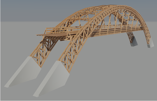 | Figure 1. Complete timber pedestrian footbridge |
4.1. Deck
- Transverse beams, hyperstatic, were composed of boards (5 cm x 20 cm), while longitudinal beams ("T" section), isostatic, spaced among them approximately 80 cm and supported on nodes of upper truss stringer that makes up mixed portico. In addition to these elements, guardrail has: vertical elements (10 cm x 10 cm) with 1.2 m height, spaced horizontally every two meters; horizontal elements ("H" section - 2 boards 2.5 cm x 15 cm and 5 cm x 6 cm rafter 1) arranged in three rows, vertically spaced every 40 cm, and first, placed to 20 cm from the floor. Figure 2 represents deck structure.
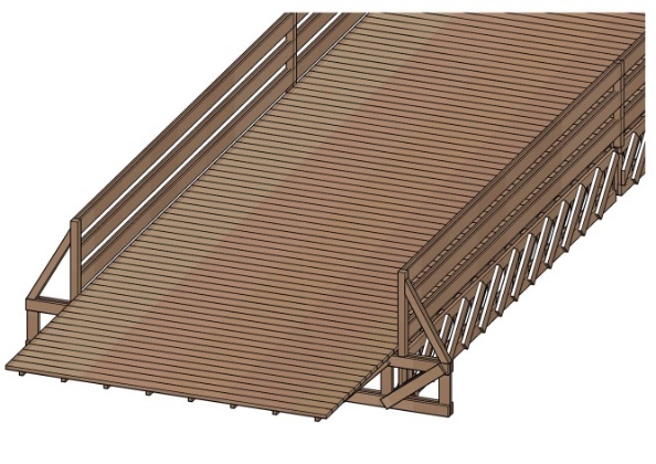 | Figure 2. Deck |
4.2. Mixed Portico
- Transversal truss serves to support longitudinal beams of deck and are attached to rods. This structure has a height of approximately 60 cm and composed by the following bars: stringer top/bottom (5 cm x15cm), vertical pieces (5 cm x15cm) and diagonals (2.5 cm x 15cm). Such trusses are fixed to trussed arches by inclined bars (rods), composed by two boards (5 cm x 20 cm). Longitudinal trusses (same dimensions of transverse truss) were designed with objective of assisting portico locking. Figure 3 represents mixed portico structure.
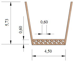 | Figure 3. Mixed portico (dimensions in meters) |
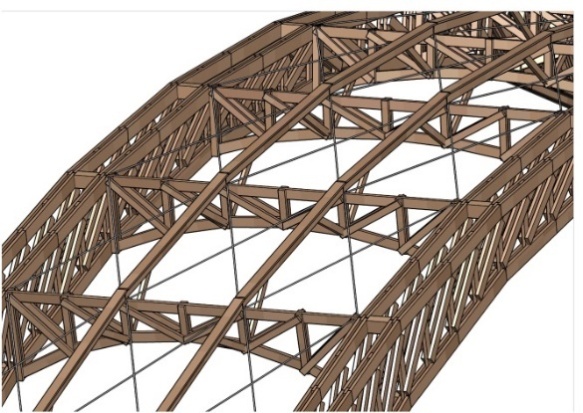
4.3. Trussed arc
- Trussed arch is composed by two structures, one on each walkway side. Each structure, internally, has the following bars: vertical pieces (2 pieces of 5 cm x 15 cm), diagonal (4 pieces of 2,5 cm x 15 cm) and lower/upper stringers (4 pieces of 5 cm x 20 cm). For provide greater transverse stiffness, bars stringers were designed with the following lateral spacing among themselves: 1st/ 2nd and 3rd /4th pieces (5 cm); 2nd/3rd pieces (35 cm). Thus, the following settings have been taken to other structural elements: Diagonal (external to 1st/2nd and 3rd/4th pieces of stringers); vertical pieces (internal to 1st/2nd and 3rd/4th pieces of stringers). Arches, in support region, have secondary diagonals (2 pieces 2,5 cm x 15 cm) whose function is to reduce length of main diagonal and thus prevent piece buckling. In order to do connection between each arc connections bars were used (5 cm x10 cm length - 35 cm), installed at every 2 meters, coincide with lower/upper stringers nodes. Figure 4 represents trussed arch structure.
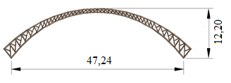 | Figure 4. Trussed arc (dimensions in meters) |
4.4. Bracing Structures
- Trussed arches (upper and lower stringers - straight and curved bars, respectively) were sized for locking of lower/ upper stringers of main arc. Such structures are formed by: upper/lower stringers (2 pieces of 2.5 cm x 15 cm), vertical pieces (1 piece of 5 cm x10 cm), diagonals (2 pieces of 2.5 cm x 15 cm). Secondary arches are locked with tie rods (steel cables with tensioners, arranged in "X"), two longitudinal beams ("T" section: soul 2.5 cm x 10 cm; top table 5 cm x 15 cm - placed in upper stringer).Longitudinal beams have French-hands (5 cm x 6 cm) at ends, acting as an intermediary support, equidistant 1 meter support from (secondary arc). In transverse direction, at its axis midpoint, steel cables are positioned (with tensioners) to promote lateral locking. All steel cables used have a diameter of 12.5 mm. Figure 5 represents bracing structures.
 | Figure 5. Bracing structures |
4.5. Connections
- Connections will be made using sheet metal and metal pins (threaded bars and galvanized steel screws).In an amendment (direction change) of stringers (upper/lower) of trussed arc were adopted sheets and metal pins to unite all converging bars. In connection of diagonals and vertical pieces in continuous bar of stringers (upper/lower), metal pins were used. In summary, the following inputs are presented: metal sheets (5,000 kg); screws (8000 units) and bars (200 meters).
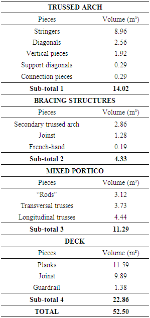
4.6. Wood Volume
- Wood needed for walkway construction are shown in Table 1.
|
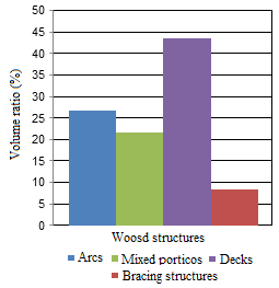 | Figure 6. Volume ratio between structures |
5. Conclusions
- From research results, it was observed that use of medium resistance classes wood when combined with an efficient structural model can be used satisfactorily, thus demonstrating quality, safety and accessibility. It also demonstrates area of engineering and building professionals that wood is a great structural material and must be put to good use because it is available in abundance in our region.As a suggestion for further work, wood consumption can be verified from other structural schemes use, considering static structure variation.
ACKNOWLEDGMENTS
- Authors thank to Wood and Timber Structures Laboratory (LaMEM), Structural Engineering Department (SET), São Carlos Engineering School (EESC), São Paulo University, by the materials and resources used in this research.