-
Paper Information
- Previous Paper
- Paper Submission
-
Journal Information
- About This Journal
- Editorial Board
- Current Issue
- Archive
- Author Guidelines
- Contact Us
International Journal of Materials Engineering
p-ISSN: 2166-5389 e-ISSN: 2166-5400
2017; 7(1): 12-16
doi:10.5923/j.ijme.20170701.02

Pulsed DC Glow Discharge Plasma Nitriding Process on the AISI 1045 Steel
 Abstract
 Reference
 Full-Text PDF
 Full-text HTML
Abhishek Sharma1, K. C. Swami2
1Jagannath Gupta Institute of Engineering & Technology, Jaipur, India
2Malaviya National Institute of Technology, Jaipur, India
Correspondence to: Abhishek Sharma, Jagannath Gupta Institute of Engineering & Technology, Jaipur, India.
| Email: |  |
Copyright © 2017 Scientific & Academic Publishing. All Rights Reserved.
This work is licensed under the Creative Commons Attribution International License (CC BY).
http://creativecommons.org/licenses/by/4.0/

In the present investigation, pulsed dc glow discharge plasma nitriding process on the AISI 1045 steel has been carried out at three different temperatures i.e., at 450°C, 475°C and 500°C for 10 hrs duration in order to achieve good nitride results. The microstructure of the base material and the nitrided layer has been examined by X-ray diffraction. Hardness property has been investigated for both un-nitrided and plasma-nitrided materials. It is observed that the microstructure of the core material remains unaltered and Iron Nitride is formed in the hardened surface layer after plasma nitriding at all the three temperatures employed. Surface hardness increases substantially after plasma nitriding. Surface hardness increases with the increase in plasma nitriding temperature due to greater diffusivity at higher temperatures.
Keywords: Glow discharge plasma, Nitriding process, AISI 1045 steel, Surface hardness & XRD
Cite this paper: Abhishek Sharma, K. C. Swami, Pulsed DC Glow Discharge Plasma Nitriding Process on the AISI 1045 Steel, International Journal of Materials Engineering , Vol. 7 No. 1, 2017, pp. 12-16. doi: 10.5923/j.ijme.20170701.02.
Article Outline
1. Introduction
- The main objective of nitriding is to increase the hardness of the component surface by enriching it with nitrogen [1-6]. The most significant advantage associated with the nitriding process is that it does not require a phase change from ferrite to austenite or from austenite to martensite of the base steel component. The bulk of the material under nitriding treatment remains in the same phase during the complete procedure [1]. The bond structure in transition metal nitrides consists of a mixture of covalent, metallic and ionic components, and is responsible for high hardness, excellent wear resistance, chemical inertness, good electrical conductivity and superconducting properties. A number of processes are available by which a wide variety of alloys can be nitride. Number of reports on this process has been published [4-9].In this paper, we have taken AISI 1045 plain carbon steel. Plain carbon steel is the most frequently used steel. A typical application for carburized plain carbon steel is for parts with hard wear resistant surface, e.g., small shafts, plunges, or highly loaded gearing. In this study, plasma nitriding parameters were examined to reveal optimal nitriding conditions originating from gas mixture, temperature and process time.
2. Experimental Procedure
2.1. Materials and Sample Preparation
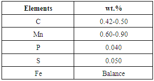
- Plain carbon steel AISI 1045 was selected for the present study and its chemical composition are shown in the table 1.
|
2.2. Plasma Nitriding Process
- This process was carried out in a 500 mm diameter and 500 mm height bell shaped stainless steel vacuum chamber. Mechanically prepared sample of AISI 1045 steel was mounted on the sample holder of the vacuum chamber. Initially, the vacuum chamber was evacuated to a base pressure of 0.05 mbar by a rotary pump [Fig. 1]. The samples were first sputter cleaned using N2–H2 gas mixture in 25%:75% ratio. The gas flow rate was controlled by the butterfly valves mounted on the vacuum chamber to maintain a pressure of 1 mbar. Plasma was generated using a D.C. pulsed power supply.
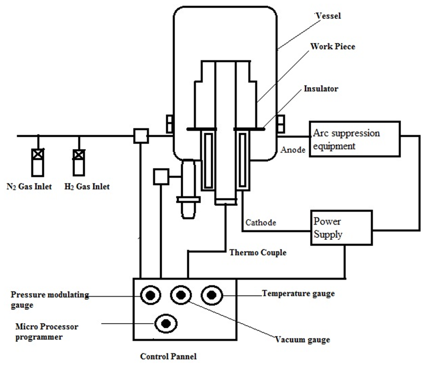 | Figure 1. Schematic of Plasma nitriding Set up |
3. Results and Discussion
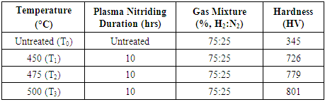
- The results obtained from hardness and nitrided layer measurements are exhibited in Table 2. At same nitriding time and three different temperatures have resulted in change of hardness and case depth of nitrided layer as well. The change in thickness of nitrided layer will probably provide superior service life.
|
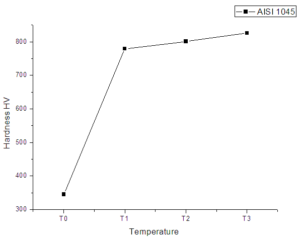 | Figure 2. Hardness curve for AISI 1045 |
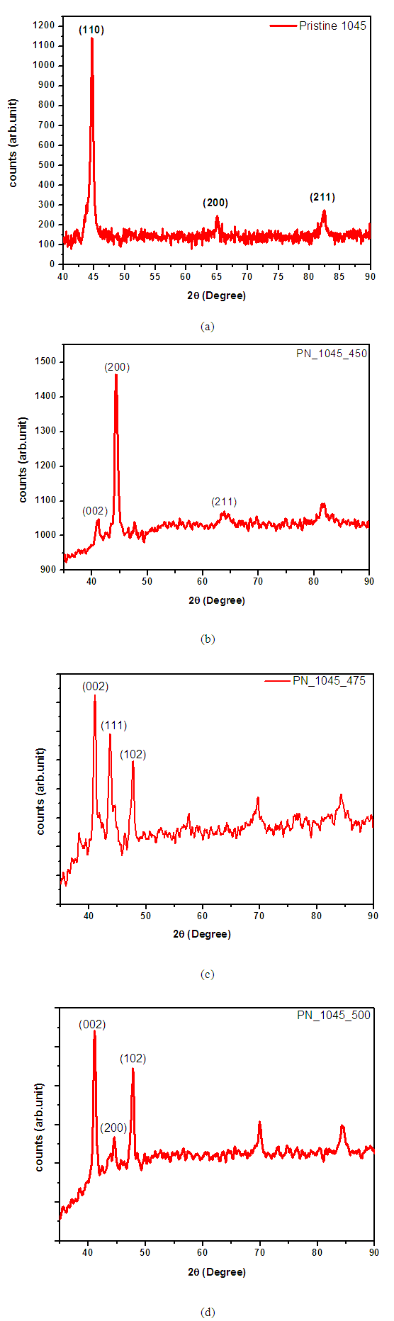 | Figure 3. Glancing-incidenceX-ray diffraction patterns ofAISI 1045, (a) untreated sample and plasma-nitrided (b) at 450°C, (c) at 475°C, (c) at 500°C |
4. Conclusions
- In conclusion we have obtained plasma nitrided AISI 1045 with predominantly epsilon-Fe3N phase on the surface. The broad peak of Fe3N confirms nitride phase formation. The Hardness profiles indicate a direct relation of the increased surface micro hardness in plasma nitrided AISI 1045 to the nitride phase formation in the nitride layer.