-
Paper Information
- Paper Submission
-
Journal Information
- About This Journal
- Editorial Board
- Current Issue
- Archive
- Author Guidelines
- Contact Us
International Journal of Materials Engineering
p-ISSN: 2166-5389 e-ISSN: 2166-5400
2016; 6(6): 173-178
doi:10.5923/j.ijme.20160606.01

The Interface Behavior Analysis of Thin Film during Ball Indentation Testing
 Abstract
 Reference
 Full-Text PDF
 Full-text HTML
Avelino Manuel da Silva Dias, Everton Carneiro da Silva
Department of Mechanical Engineering (DEM), Federal University of Rio Grande do Norte (UFRN), Natal, Brazil
Correspondence to: Avelino Manuel da Silva Dias, Department of Mechanical Engineering (DEM), Federal University of Rio Grande do Norte (UFRN), Natal, Brazil.
| Email: |  |
Copyright © 2016 Scientific & Academic Publishing. All Rights Reserved.
This work is licensed under the Creative Commons Attribution International License (CC BY).
http://creativecommons.org/licenses/by/4.0/

The search for improved tribology properties in materials contributes to the development of processes that extend the useful life of components and their applications in increasingly severe environments. In this respect, thin ceramic films have been used to enhance the properties of components that operate under these conditions. However, expensive experimental assays are needed to assess the behavior of these films and system compounds by films and substrates. These experimental analyses are also destructive, requiring the use of sophisticated equipment and specialized hand tools. On the other hand, with advances in computational mechanics, the application of numerical analysis to solve numerous technological problems has become increasingly common, owing to its low operational costs. This study aims to simulate indentation testing with a spherical penetrator in systems composed of thin CrAlN ceramic film deposited on AISI 4140 metallic substrate using a Finite Element commercial code. The main objective of this study was to evaluate the field behavior of stresses in the contact region of the indenter with the sample and on the film-substrate interface.
Keywords: Finite Element, Ball Indentation Testing, Thin Film, Interface Behavior
Cite this paper: Avelino Manuel da Silva Dias, Everton Carneiro da Silva, The Interface Behavior Analysis of Thin Film during Ball Indentation Testing, International Journal of Materials Engineering , Vol. 6 No. 6, 2016, pp. 173-178. doi: 10.5923/j.ijme.20160606.01.
Article Outline
1. Introduction
- The need to improve mechanical properties, such as resistance to oxidation and wear, has led to advances in surface engineering. This field of engineering involves the preparation and modification of surfaces to fulfil specific functions within certain applications. One of the options employed to improve these surface properties is the use of ceramic coatings obtained by deposition processes such as Physical Vapour Deposition (PVD). However, the mechanical properties of these films and their interface as substrate must be assessed.Indentation tests have been applied during the last hundred years to determine surface hardness in different classes of materials. In recent years, instrumented indentation testing has been used to characterize tribology systems [1]. The instrumented indentation technique is conducted using precision instruments equipped with sensors that monitor variations in penetration depth (h) of a penetrator as a function of the applied load (P) when it penetrates the study material, reaches maximum displacement, and then returns to the initial position, completing a loading and unloading cycle [2]. Due to their versatility, a large number of studies have been carried out to investigate new methodology and applications for these assays. Recent proposals used indentation tests as a tool to assess the mechanical characteristics of materials such as surface hardness (H), Young´s modulus (E), Poisson coefficient (ν), fracture toughness (KIC), film thickness (t) and a stress behavior curve as a function of elastic-plastic strain [3-9]. However, implementation of this experimental methodology to assess mechanical properties and the results obtained still raise doubts in the scientific community. According to the literature, these problems are more serious when assessing the mechanical behavior of thin films deposited on soft substrates [2, 7].Due to these limitations in analysing indentation tests, the use of a numerical technique capable of evaluating stresses and strains during the indentation cycle may contribute to a better interpretation of this test. Recently, this numerical methodology has been studied using the Finite Element Method (FEM) to assess the behavior of different materials in indentation testing [9-15].The FEM has been proved a reliable numerical technique for analysing stresses and strains and simulating different engineering problems. This method has widely been used to simulate and resolve numerous nonlinear problems related to structural instability and dynamic, electromagnetic, and mechanical forging process. However, the use of this numerical technique to assess the indentation test in thin surface coatings has also had problems mainly due to computational limitations, difficulty in implementing damage criteria and, chiefly, in characterizing these coatings [7, 14-16].The simulation presented in this study used FEM models to reproduce the indentation test with a spherical indenter, as illustrated in Fig. 1. The system under study was composed of a metallic substrate coated with different thicknesses of a ceramic film. A simulation was also used to assess the mechanical behavior of the interface in these systems that combine high-hardness coatings with a middle-hardness substrate. This interface was modelled by introducing a thin layer of elements with mechanical properties capable of simulations ranging from perfect adhesion to possible delaminating of the film.
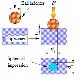 | Figure 1. Illustration of ball indentation testing , where D is the diameter of the indenter, h is the indentation depth, d1 and d2 are diameters of the impression at specimen and P is the force applied to the indenter [1] |
2. Methodology
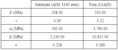
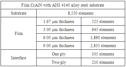
- The numerical simulation performed in the present study used the finite element commercial software to model the indentation test with a spherical penetrator in a thin ceramic film deposited on a metallic substrate [17]. Due to the symmetry of the problem, axis symmetric elements were used in the numerical model, significantly decreasing computational efforts [1]. The studied system was composed of an AISI 4140 alloy steel substrate coated with a chromium aluminium nitride (CrAlN) film with four different thicknesses, i.e., 1.67 μm, 3.00 μm, 6.00 μm and 9.00 μm. These studied materials, of both the film and the substrate, were considered isotropic and homogeneous. The elastic-plastic behavior of these materials was illustrated by means of a curve depicting the linear elastic regime and plastic yield (Equation 1), primarily as described by Hosford and Caddell [18]. In this expression, σ and ε are effective stress and yield limit, respectively. K is a constant that describe the strain hardening characteristics of the material and n known as the strain-hardening coefficient [7-8, 18].
 | (1) |
|
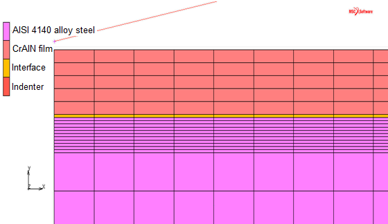 | Figure 2. Numerical model at the contact region of ball indentation testing in a system with film, interface and substrate |
|
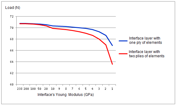 | Figure 3. Behavior of the maximum indentation load as a function of Young´s modulus at the interface for the system with 3.00 µm thick film |
3. Results and Discussions
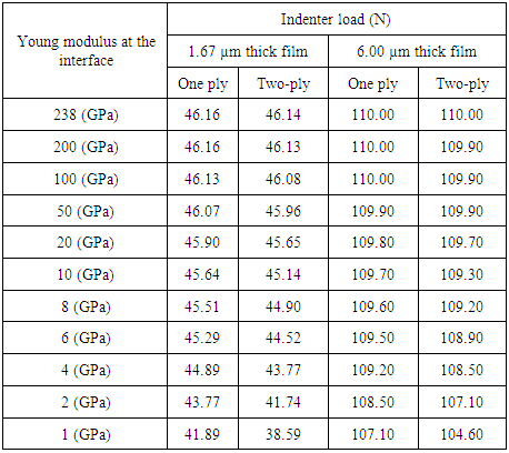
- Table 3 illustrates numerical results of the maximum indentation load as a function of Young´s modulus in the interface for a model with two different thick film and a penetration depth at a half of these thicknesses. It was considered to be optimal adhesion between film and substrate when the interface modulus was equal with the substrate, i.e., 238 GPa. The value of Young´s modulus was reduced gradually, where indentation testing with low adherence between the film and the substrate was simulated. The numerical results for indentation load show little change in its value in the function of the variation of the interface modulus and the number of ply of the interface. However, in all cases, for low values of the modulus of elasticity, for example, less than 10.0 GPa for 1.67 µm thick film, there is a significant reduction of indenter load, in both of the different models used to represent the interface. However, for thicker films, this behavior was less critical. In other words, a greater film thickness leads to a better distribution of the stresses in the film, without overloading the interface. This behavior of thicker films has been observed in the literature [1, 3].
|
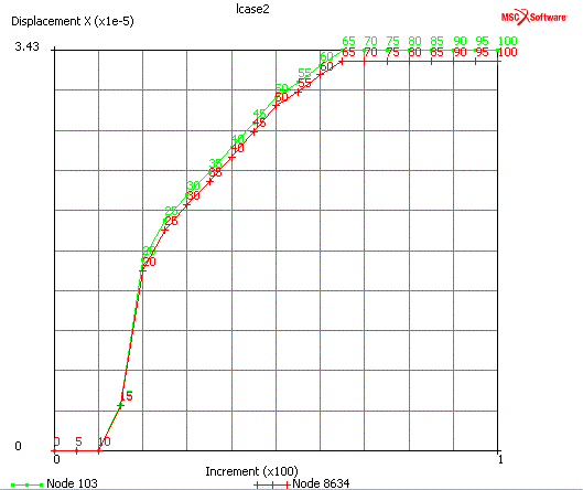 | Figure 4. Graph of radial displacement between node 103 and node 8,634 during indentation testing for a system with 3.00 μm thick film and two-ply of elements at interface, with Young´s modulus of 200 GPa |
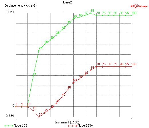 | Figure 5. Graph of radial displacement between nodes 103 and 8,634 during indentation testing for a system with 3.00 μm thick film and two-ply of elements at interface, with Young´s modulus of 2.0 Gpa |
4. Conclusions
- Based on the numerical results of the indentation test with spherical indenters using the finite element method, it was concluded that from its overall behavior, the models represent the indentation test in different systems composed of a hard film (CrAlN), with different thicknesses, deposited in a metallic substrate with high mechanical strength (AISI 4140 steel).In this study, an attempt to represent the behavior of the interface region during the indentation testing by varying the refinement of the mesh, the value of its Young´s modulus and the number of ply elements. The results showed that the models were able to represent since a perfect adhesion between the film and the substrate to a weaker adhesion. Evaluating these results, by analyse the maximum load indentation was possible to identify delamination of interface region for the lowest values of its Young´s modulus.However, there is still need for a more thorough numerical and experimental analysis in order to introduce a parameter capable of more representative modelling of film-substrate adhesion.
ACKNOWLEDGEMENTS
- The authors gratefully acknowledge the financial support by CNPq (Brazilian foundation for the support of research), under grants process 460943/2014-6 MCTI/CNPq/Universal 2014. They also thanks for the CAPES (Higher Coordination Brazilian Agency for Scientific and Educational Training), through process BEX 6569-14.