Ricardo de Mello Scaliante1, Diego Henrique de Almeida2, Carlito Calil Junior3, Raquel Schmitt Cavalheiro4, André Luis Christoforo5, Francisco Antonio Rocco Lahr3
1Transportation Infrastructure, Departamento Nacional de Infraestrutura de Transportes (DNIT), MS, Brazil
2Department of Engineering, Pitágoras College, Poços de Caldas, Brazil
3Department of Structural Engineering (SET), São Paulo University (EESC/USP), São Carlos, Brazil
4Department of Materials Engineering, São Paulo University (EESC/USP), São Carlos, Brazil
5Centre for Innovation and Technology in Composites – CITeC, Department of Civil Engineering (DECiv), Federal University of São Carlos, São Carlos, Brazil
Correspondence to: André Luis Christoforo, Centre for Innovation and Technology in Composites – CITeC, Department of Civil Engineering (DECiv), Federal University of São Carlos, São Carlos, Brazil.
| Email: |  |
Copyright © 2016 Scientific & Academic Publishing. All Rights Reserved.
This work is licensed under the Creative Commons Attribution International License (CC BY).
http://creativecommons.org/licenses/by/4.0/

Abstract
Brazil is a continental size country with several rivers that creates a large demand for short and medium span bridges for which timber is a renewable and ecologically friend option for material for building, once resists well for quick loadings. Using Glued-laminated timber (glulam) allows the fabrication of large dimension pieces, resulting in good stability and high quality control providing safety and reliability for the structures. This work has the aim of providing criteria for the verification, based on ultimate state limit method, for bridges with glulam girders and transversal deck panels in glulam, applying procedures described by renowned researchers and adapting them for Brazilian Code conditions. Tables for pre-dimensioning for such kind of bridges with span ranging from 8 to 20 m for TB-30 and TB-45, as well as construction details.
Keywords:
Glued-laminated timber, Timber bridges, Pre-Dimensioning, and superstructure
Cite this paper: Ricardo de Mello Scaliante, Diego Henrique de Almeida, Carlito Calil Junior, Raquel Schmitt Cavalheiro, André Luis Christoforo, Francisco Antonio Rocco Lahr, Brazilian Criteria Ultimate Limit States Verifications for Glulam Girders and Glulam Transversal Deck Panels Bridges, International Journal of Materials Engineering , Vol. 6 No. 4, 2016, pp. 134-145. doi: 10.5923/j.ijme.20160604.03.
1. Introduction
Brazil has a large hydrographic network spread throughout its territory that demands the construction of short and medium span bridges to connect cities and villages. The construction of vicinal roads bridges upon accelerating the economical evolution of a certain area lead to a human development of the residents directly influencing the life quality of the population [1]. It is also important to note that improvement in transportation conditions, with the construction of new bridges reduces costs, shortens distances as well as making possible the industrial developing of the area generating direct and indirect jobs.Timber was probably the first material used by humans in bridges building. However in Brazil the constructive process is stagnated once the majority of timber bridges has not been designed by capacitate professionals nor built by qualified technicians, without using treated wood and even less receiving the required maintaining, thus resulting in high cost structures, safe less, less durable and directed to ruin what make a bad reputation for timber as a structural material. Researches performed in the Laboratório de Madeiras e Estruturas de Madeira (LaMEM, Escola de Engenharia de São Carlos, Universidade de São Paulo), demonstrated that c.a. one thousand bridges and footbridges among those in use, should be rebuilt or refurbished [2]. Besides presenting interesting properties such as high tensile and compressive resistance, low dead weight and excellent impact absorption, high-desired characteristics for bridges, the use of Wood from planted forests for construction of bridges is a sustainable option given that during tree growth has the absorption of carbon dioxide from the atmosphere and also the production of oxygen during photosynthesis, thus being an environmentally friendly material comparing with steel and concrete, structural materials coming from non-renewable sources, which require large amounts of energy in their production.The usage of Glued-laminated Timber (Glulam) it is widely used in projecting timber bridges in Europe and North America, however in Brazil few is known regarding bridges made from such material. There is the record of one glulam bridge built in USP Campus II at São Carlos-SP, however it is a multicelular deck bridge protected with multicellular prestressed across the board, with only the beams in Glulam [3].Glued-laminated timber represents a contemporary material produced by factories with high quality control, mechanical and visual classification of the timber parts, allowing the production of pieces with various sizes, straight or curved, just pasting sawn boards with 5 cm maximum thickness with structural water and weather-resistant adhesives. Such glulam parts provide greater resistance when compared to sawn pieces, once the rigid classification one-by-one, allows the best use of wood, besides the possibility of producing large structural parts with greater inertia and lengths.The stringer beams system is the most common and simplest type of timber bridges. Associated to the use of glulam it is possible producing parts of various heights, widths and lengths able to overcome large spans and more easily meet the Ultimate Limit State (ULS) and Serviceability Limit State (SLS) specifications. Furthermore, the great advantage is those stringer beams can cambered to offset dead load deflection. The bridge deck is formed by glulam transverse panels are supported by the stringers. Such panels must be able to receive load from vehicles, resisting to this loading and present small displacements and rotations between them. To make the deck continuous, the joints are stiffener beams used with through bolts to interconnect the panels and also provide a gain of rigidity to the deck, thus reducing excessive vertical displacements that are harmful to the surface coatings of the bridge and also reducing excessive vibration during the passage of vehicles. The present work aims the presentation of theoretical procedures for verifying of the state limit for bridges from glulam and decks in glulam transverse panels, elaborating pre-sizing tables for the Brazilian Vehicle Live Loads and timber. Some relevant constructive details are also presented.
2. Material and Methods
Timber is an appropriate material for bridges construction for several reasons among which the capability of resisting to high loadings in a short time interval [4]. Furthermore, it is light, easy to handle and weather resistant. That there is a prejudice in Brazil regarding usage of timber in the construction of bridges either by the user and by financial agents, being this one of the main obstacles to the use of this material for construction of new bridges in the country [5].Timber growth and extraction as well as primary processing, involve low energy consumption without damage to the environment, thus being the wood an ecologically friend material in opposition to other materials used in bridges construction as steel and armed concrete, produced by highly pollutant procedures, preceded by environmental aggression during raw material extraction, derived from nonrenewable sources and demanding high energy consumption during production [6]. Using reforesting wood besides do not generate pollutant residues, one has solar energy consumption for the production of the wood material, carbonic gas absorption and concomitant production of oxygen that is liberated to atmosphere.Timber bridges have low cost, easiness of construction and long lasting of timber bridges when appropriate technical procedures and preservative wood impregnation are used in the parts of the timber structure [1, 7]. A bridge deck with properly waterproofed and treated surface has a useful lifetime of at least fifty years [8].Glulam stringers bridgesGlulam stringers bridges are built with a series of stringers positioned parallel to the traffic direction. These beams are fabricated with selected and classified lamellae with thickness up to 5 cm, glued to each other by the wide faces with a water proof structural adhesive. This represents an industrial process with rigid quality control that results in safer and trustable structures. This kind of bridges require lower amount of glulam beams being able to span greater distances than those built from lumber beams [9].Structural bridge system in glulam beamsThe system in stringer beams consists in a series of beams positioned in longitudinal direction parallel to the traffic that supports a series of transversal panels that forms the bridge deck [9]. Being the main components that receive the entire load from the deck these beams must be resistant enough to attend the limits of service regarding the maximal vertical displacement. The beams system is composed basically by three components: stringers, bracing (that avoid the side instability, Figure 1) and the supporting sets.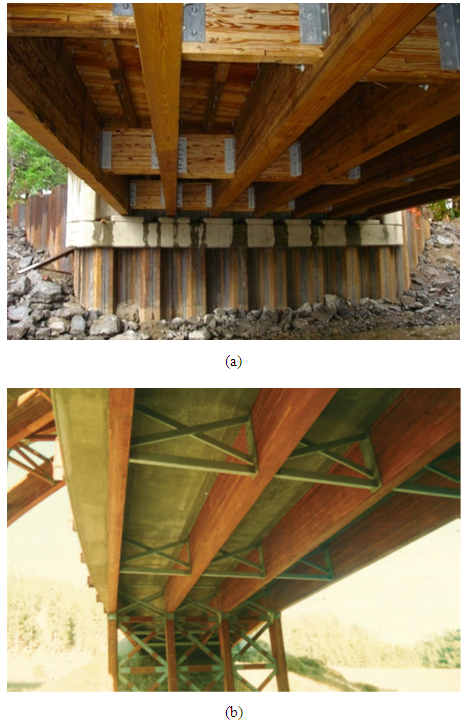 | Figure 1. Stringer beams and bracing of the type (a) diaphragm [10] and (b) truss [11] |
The beams are structural parts produced from 5 cm maximum thickness layers horizontally positioned and glued by the wide faces and receiving the load from the deck perpendicularly to such faces. Thus after visual and mechanical classifications of these layers those with better ranking must be placed in the positions were the highest tension in the glulam beam (Figure 2.a). Furthermore, they are elements produced in many different dimensions in order to provide greater dimension stability when compared to the lumber parts. They can also be produced cambered reducing vertical displacements generated by the permanent and eventual loads. The beams are projected to attend at the ULS for the main stress: the bending moments and the horizontal shear. The glulam decks are confectioned from vertically laminated panels. These panels are placed transversally regarding the stringer beams, while the loading force acts parallel to the faces of the glued layers (Figure 2.b). The glulam decks are more resistant and rigid when compared to those from nail laminated timber, due to the homogeneity of the glue binding homogeneity between layers, which better distributes the stress between them [9]. The panels are glulam parts totally pre-fabricated and if properly treated with chemical preservatives, can provide a useful life of at least 50 years.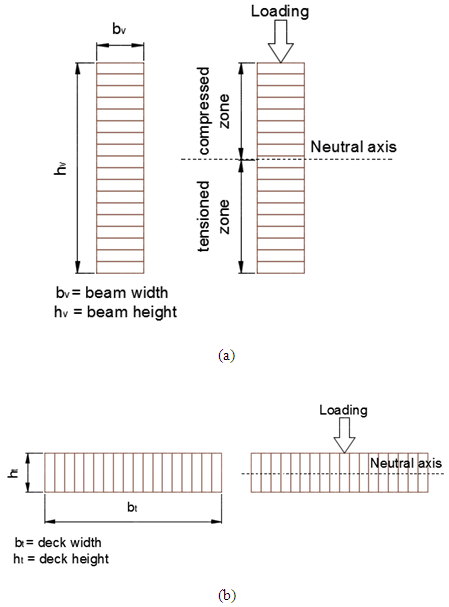 | Figure 2. Loading configuration (a) in the stringer beams and (b) in the deck |
The usage of single panels is done by positioning them on the stringer beams without any connection between adjacent panels. It is a non-expensive and fast, however subject to serious problems such as excessive relative vertical displacements and consequently is less recommended for asphalt coating bridges with intensive traffic of vehicles due to the appearance of cracks as illustrated in Figure 3a. Researches have proposed solutions using stiffener beams in parallel to the stringer beams interconnecting the panels [12-14]. The use of panels interconnected by stiffener beams proportioned a better transfer of stress between adjacent panels reducing the displacement and relative turn between them while significantly improve the stiffness of the deck reducing the vertical displacement and maximum tension acting on them. Such gains in stiffness reduces the appearance of cracks in the asphaltic coating on the deck, preventing water penetration and, consequently, the deck wood decay. Such solution is appropriate for bridges with high traffic of vehicles and to those in which asphaltic coatings are used. (Fig. 3b).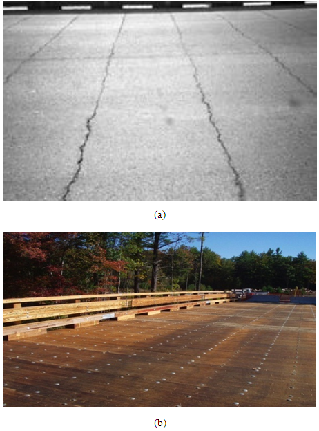 | Figure 3. (a) cracks in the asphaltic coating generated by the relative displacement among the panels [15]; (b) deck from transverse panels interconnected by stiffener beams [16] |
The use of stiffener beams with through bolts in glulam transverse panels connection with the deck to transmit shearing forces and bending moments present better performance force cyclic loadings when compared with panels interconnected by steel pins previously used in the panels interconnections [13]. Studies pointed that for several spacing between beams the stiffener beams must have minimum rigidity (EI) of 230 kN.m² and maximum of 460 kN.m² [14]. In the Lighthouse Bridge structure over the Upper Salt Creek north of Olympic Peninsula in Callum Country, WA, EUA, built in 1994, with a 31 m length and 10,5 m width, with two traffic lanes, it have been used stiffener beams between glulam stringer beams [15]. A check out of the deck in October 1999 do not revealed cracks in the asphaltic coating, confirming the efficiency of such system as presented in Figure 4.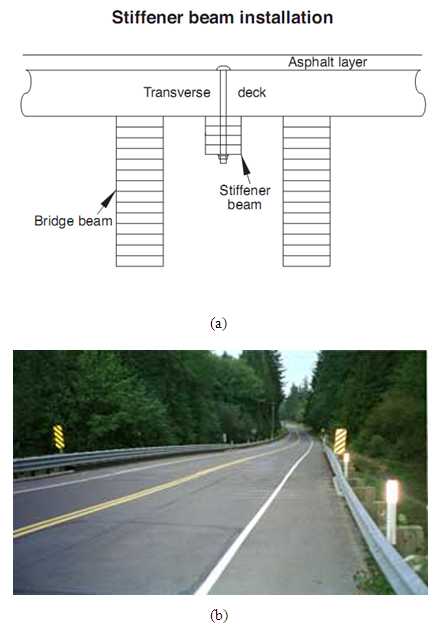 | Figure 4. (a) Stiffener beam installation; (b) absence of crack in the asphaltic coating due to the relative displacement of the panels. [15] |
The use of though bolts in the deck stiffener beam binding (Figure 4a) revealed being efficient and non-expensive method for solidarization between the elements due to the ease of obtaining this type of screw. This binding lead to a more favorable distribution of the stresses along the panel.In order to facilitate and speed up the assembling of the beams is necessary to standardize the execution of the pre-holing that should be done before the chemical treatment of the parts resulting in a more economic and long lasting structure.Recommended the use of dome head bolt instead of hex bolts once the first ones do not damage the waterproof layer between the deck surface and the asphaltic coating surface [14].In addition to the use of stiffener beams for interconnecting the deck panels, proposed the use of geosynthetics materials in Wood Bridges such as the geogrids that reduced the propagation of the reflexive cracks in the coating, besides improving the adhesion between the wood deck and the asphaltic material, establishing a water-proof layer and increasing the useful life of the deck [17].Theoretical Criteria for Verifying USL and SLS in Bridges with Girders and Transversal Deck in GlulamThe use of glulam timber as an option for bridges structures building in Brazil is subject to the researches and studies related to the employment of such material in conditions that match the country reality. There are many handbooks and pre-dimensioning of glulam-based bridges in countries of Europe and North America, however the conditions are totally diverse from those in Brazil, be by the kind of wood employed, be by loadings from traffic, snow and other differences from Brazilian patterns.So, it is important to present criteria for the verification of the glulam bridges for the Brazilian territory, according the technical Codes of that country as well as considering the technical recommendations from international researchers.Theoretical analysis of deck in glulam panelsFor the theoretical analysis of a deck in order to obtain a simplified and conservative result of the tensions and displacements generated by the load from an insulated wheel of the vehicle live loads, positioned in the regions that allows obtaining the highest bending and shear forces as well as with the permanent loading as the self weight of the deck and of the asphaltic coating the recommendations are considered [9]. According to [9], the deck panel should be considered analogously to a single insulated beam supported on the stringer beams. For the theoretical free span is recommended adopting the distance between the internal faces of two adjacent stringer beams plus half the width of a stringer beam (bv).Regarding the wheel load used there will be considered the Brazilian vehicle live loads TB-30 and TB-45, according to the Brazilian standard ABNT NBR 7188:1988 [18], in which it is possible to observe its characteristics related to the live load uniformly distributed, quantity of axis, wheel contact width and others.For the determination of the effective width (t) of the wheel loading on the deck, it is considered the configuration represented in Figure 5, for the thickness of the deck (ht) and the thickness of the asphaltic coating (hrev) and the Equations (1), (2) and (3). | (1) |
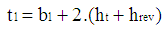 | (2) |
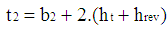 | (3) |
As dead loadings acting on the deck panel must be considered the own weights of the timber deck, of the asphaltic coating and of the metal connections. As accidental loadings must considered the action from the live loading (TB-30 and TB-45) according to the Brazilian standard ABNT NBR 7188:1988 [18]. For these it must be taken in account the impact coefficient and load coefficient according to the Brazilian standard ABNT NBR 7190:1997 [19] as well as considerations regarding the combination and reduction factors in agreement with the Brazilian standard ABNT NBR 8681:2003 [20].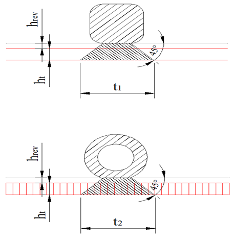 | Figure 5. Determination of the effective width of the wheel |
For calculation of the resistance of the deck panel are used the Brazilian standards ABNT NBR 7190:1997 [19] e ABNT NBR 7190:2011 [21] considering the kind of lumber to be used, its resistance class and taking the modification coefficient (kmod) according to the main loading class on the structure, the humidity classes and the classification or not of the lumber parts. Such verifications must attend the conditions established for the ULS and SLS.Theoretical analysis of the glulam beamsFor the theoretical analysis of the deck panels of the bridge, looking for the theoretical dimensioning of the beams must be determined their influence area, considering the spacing between the elements. For this it will be considered all the dead loadings represented by the own weights of the beams, of the deck, of the asphaltic coating, of the barriers and railing and metal connections. From such loadings must be determined the stresses generated by such loading for each influence area of each beam. Regarding the live loadings as the vehicle live-load must be also positioned to determine the most unfavorable case in which the largest stresses are obtained in the structure (Figure 6). Each influence area is determined by the distance between the longitudinal axis of the adjacent stringer beams according Figure 7.Thus each stringer beam behaves as a “T” formed together with the deck. However the connection between such elements by hex bolts is not perfect. A displacement of the connection occurs that can be determined according procedures described in the EUROCODE 5:2004 [22] and in the Brazilian standard ABNT NBR 7190:2011 [21] and thus one can calculate the effective stiffness of the section under consideration.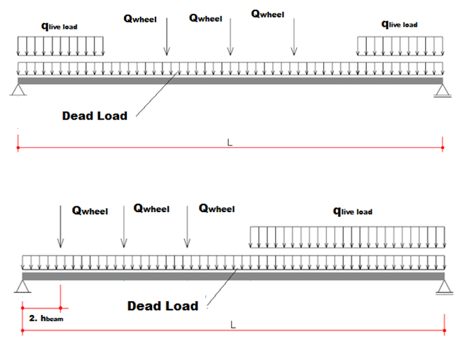 | Figure 6. Positioning of the live load vehicle for each case of critical bending moment and displacement (a); and for the critical shear force (b) |
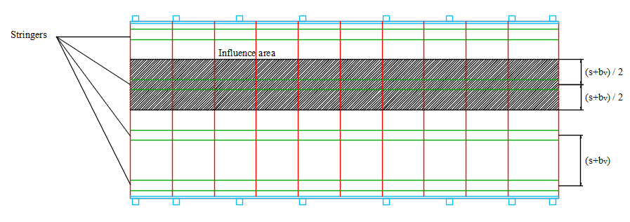 | Figure 7. Influence area of each stringer beam |
The theoretical analysis of the beam "T" as a piece composed integrally is made by determining the normal maximum stresses in the most requested fibers at the ends of the greater bending moment acting on the beam section as well as the horizontal ultimate shear stress for ULS, according to the Brazilian standard ABNT NBR 7190:2011 [21]. For the SLS must be verified the maximum displacements that must be lower than established by the Brazilian standards ABNT NBR 7190:1997 [19] e ABNT NBR 7190:2011 [21].For determining the values of the stresses as above for the composed “T” beams one uses the recommendations of the Brazilian standard ABNT NBR 7190:2011 [21] determining the connection sliding modulus for the SLS, Kser, in N/mm, calculated according to Equation (4) being ρk the apparent density of the lumber in kg/m³ and “d” the diameter of the screw, in mm. The sliding modulus for the ULS is given by Equation (5).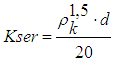 | (4) |
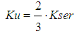 | (5) |
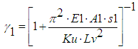
For this kind of binding there is a reduction in inertia of the set being possible to calculate the effective stiffness of the section by Equation (9), in which:Ei = elasticity modulus of each element in the transverse section;Ai = area of each element f the transverse section;ai = distance from the centroid of the area of each element that composes the section until the y-y neutral line;si = spacing of nails in the elements interface;Ki = sliding modulus of connection elements;Lv = effective span of the beam;γ1 , γ2 = inertia reduction factors; | (6) |
 | (7) |
The spacing between screws can be uniform or vary according to the shear force, from smin to smax, being smax ≤ 4 smin. In last case an effective spacing value, calculated by Equation (8) can be used.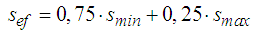 | (8) |
 | (9) |
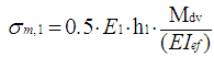
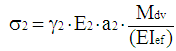
The normal stresses acting on the beam section (Figure 8) are determined by Equations (10) to (15).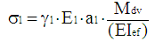 | (10) |
 | (11) |
 | (12) |
 | (13) |
 | (14) |
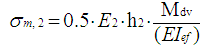
 | (15) |
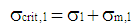
Hence: Mdv= Design value of the maximum bending momentσ1= normal stress in the centroid of the deck panel areaσ2= normal stress in the centroid of the beam areaσm,1= normal stress of the fibers of the deck upper edge of the due to the bending momentσm,2= normal stress of the fibers of the deck lower edge of the due to the bending momentσcrit,1= critical normal stress of the upper edge of the deck panelσcrit,2= critical normal stress on the lower edge fibers of the beam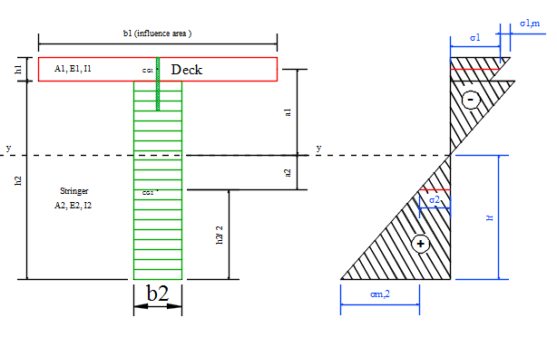 | Figure 8. “T” beam section composed by the stringer beam and by the deck and the scheme for the normal stress from the bending acting on this section |
The maximum shear is located at the neutral line of the section and is given by Equation (16) | (16) |
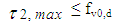
Hence:Vdv = the maximum shearing force and calculus of considered section of the beamThus the verifying conditions for the ULS must be satisfied. | (17) |
 | (18) |
 | (19) |
Finally the maximum shearing force acting in a connector (screw) (F1) interconnecting the deck panel to the stringer beam can be determined as a function of the design shearing force acting in the region where it meets the interconnection (Vdv).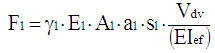 | (20) |
Regarding the vertical displacements they must be evaluated in the SLS according to the calculation efforts for the Limiting State. One of the greater advantages of the glulam beams is the fact that they can be manufactured cambered. The use of cambered beams with 1.5 to 2 times the regular value for those arrows from permanent actions for beams up to 15 m long and 1.5 to 2 times the value of the arrow from the permanent actions plus half of the arrow from the accidental actions for beams larger than 15 m [9].Other important factor to be considered during the dimensioning of the stringer beams is the support of them. Such beams must be supported on a elastomeric rubber layer commercially available as Neoprene [9]. The beams must also be fixed in supports in order to reach the calculation conditions with fixed or mobile supports using metallic corners and screws. The beams must also be analyzed regarding compression normal to the fibers in the supporting region.The checking of the stringer beam side instability must also be considered according to the ABNT NBR 7190:1997 [21], by determining the maximum beam length that dispenses the use of bracing elements, distributing the elements needed by the beams length. Recommended the use of bracing elements in the beams at least each 6m [9].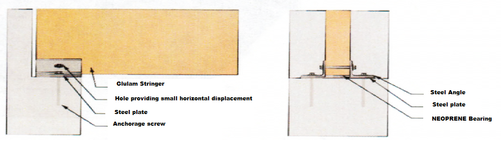 | Figure 9. Details of the support of the stringer beam from glulam [23] |
3. Results and Discussion
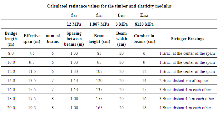
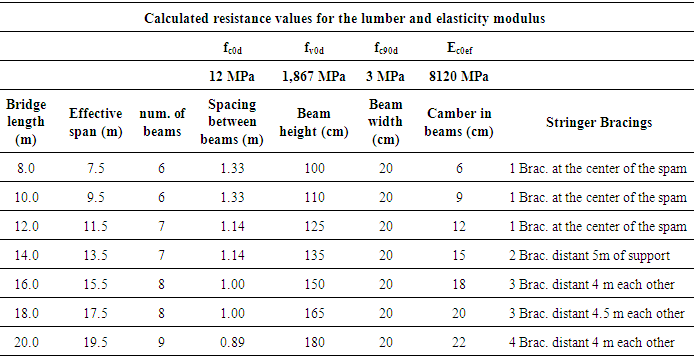
Timber BridgesFollowing the procedures previously described two pre-dimensioning tables had been elaborated for glulam beams and panels of deck. It was chosen coniferous wood of the C30 strength class related to parts classified as Pinus oocarpa a common tree in reforesting areas, permeable to the chemical preservatives in autoclave, giving higher durability to the structure.Regarding the modification coefficients used it were considered the long lasting loading (kmod1=0.70), moisture class 3, considering an average relative moisture ranging from 75% and 85% (kmod2=0.80) and last the use of mechanically and visually classified parts, characteristic essential in the industrial production of structural glulam elements (kmod3=1.00).The bridges here represented presents a 12 cm thickness of the deck and 8 m width designed a bridge with two traffic lanes and the tables are presented for Brazilian-like vehicles of the type TB-30 and TB-45.Constructive ElementsFor an appropriate construction of a Bridge from glulam beams and decks panels it is mandatory that several assembling elements are executed in order to work harmonically and to bring benefits to the stability of the bridge structural system.In Figures 10 to 15 there are presented some constructive assembling indicated to glulam bridges to complete the pre-dimensioning tables previously presented [6, 9, 11, 23, 24].Table 1. Bridges from glulam beams and decks panels for TB-30
 |
| |
|
Table 2. Bridges from glulam beams and decks panels for TB-45
 |
| |
|
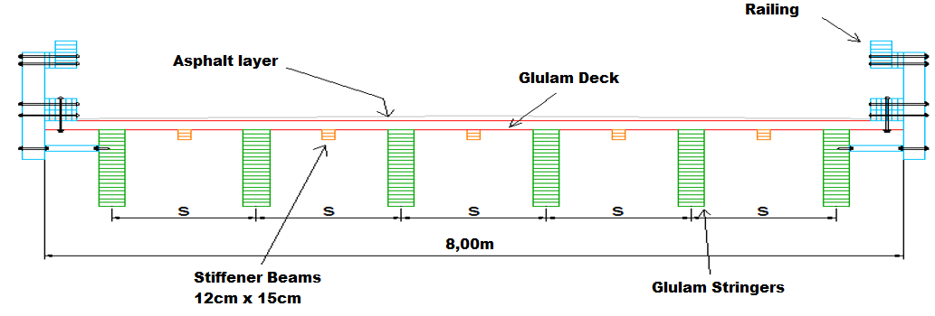 | Figure 10. Transversal Section Glulam Bridge |
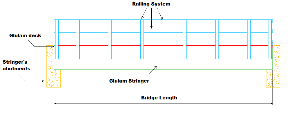 | Figure 11. Glulam bridge side view |
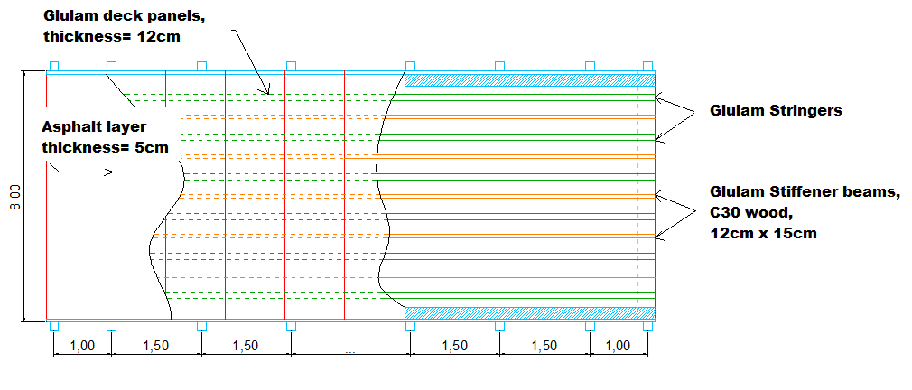 | Figure 12. Glulam bridge detailing coating, panels, stringer beams, stiffener beams and railings |
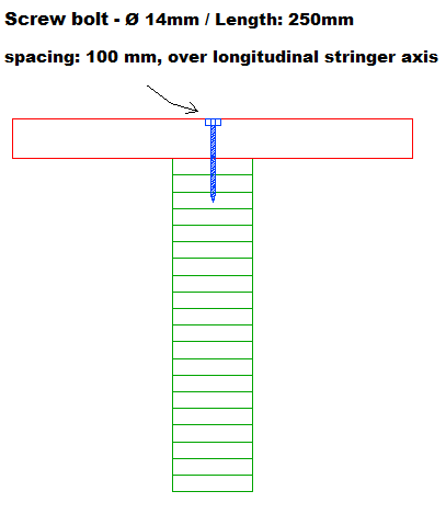 | Figure 13. Detail of the connection between glulam panels and stringer beams |
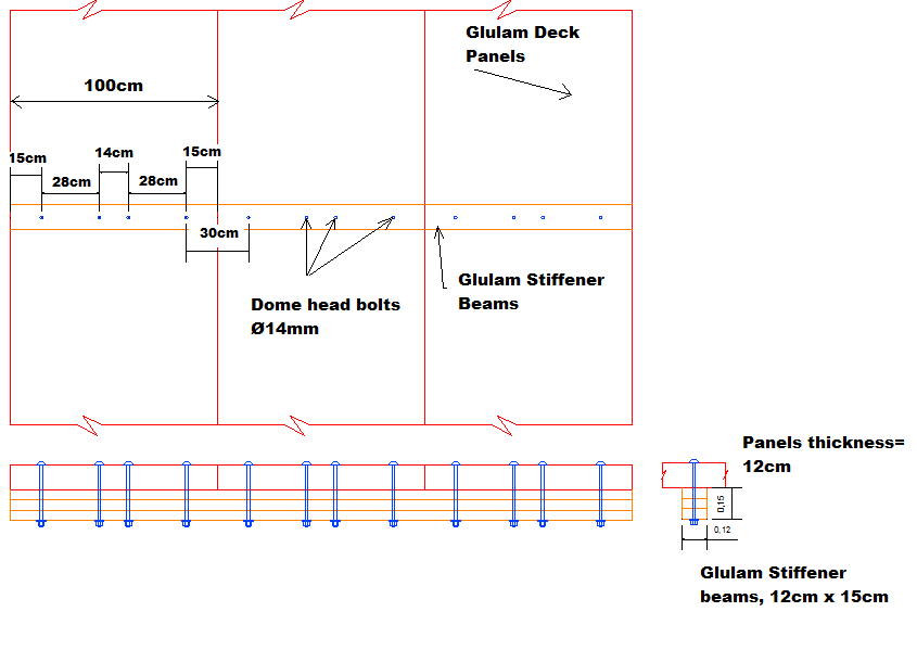 | Figure 14. Detail of the panels interconnections by the stiffener beams with dome head bolts |
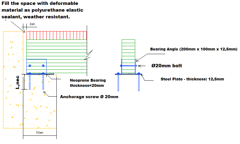 | Figure 15. Detailing of the connection of the stringer beams on the supports by the bearing angles, screws, steel plate and elastomeric rubber |
4. Conclusions
The glulam stringers bridge are common structural systems used in many countries as USA, Canada, Chile, Italy, Sweden, Swiss, Germany, Norway, among others. In Brazil there was not any research aiming to present the basic procedures for the verification of this kind of structure and even less pre-dimensioning parameters to start projects.The durability of a bridge from lumber structure is directly related to the treatment of the structural elements as well as their periodic maintenance. For the pre-dimensioned structure it was chosen the Pinus oocarpa lumber treated with CCA (chromated copper arsenate) or CCB (chromate copper boron) preservatives in an autoclave (under pressure). The use of glulam parts in the construction of bridges can be benefited from its versatility and excellent structural behavior as well as the possibility of using cambered elements minimizing deformations provided by dead or live loadings, with the advantages of permitting the assembling of structural parts of large dimension and lengths able to attend to different spams required in each particular project. A glulam beam of 20 cm x 18 cm x 20 m weighs 4.320 kg in average while a similar beam from armed concrete with the same dimensions weighs 18.000 kg. Thus the use of glulam leads to a significant reduction in expenses with foundations for bridges.
ACKNOWLEDGMENTS
The authors are grateful to the CNPq for financial support, the facilities of Wood and Timber Structures Laboratory (LaMEM) which was essential for this research development in addition to the Department of Structural Engineering (SET), São Carlos Engineering School (EESC), University of São Paulo (USP).The author also thanks the Brazilian National Department of Transportation Infrastructure (DNIT).
References
| [1] | Hellmeister, J. C. Pontes de Eucalipto Citriodora. In: I ENCONTRO BRASILEIRO EM MADEIRA E ESTRUTURAS DE MADEIRA. Anais do I Encontro Brasileiro em Madeiras e Estruturas de Madeira, Volume 5, 78p. São Carlos, 20 a 22 de julho de 1983, 1983. |
| [2] | Calil Junior, C. et al. Manual de projeto e construção de pontes de madeira. São Carlos: Suprema, 2006. 252p. |
| [3] | Góes, J. L. N.; Calil Junior, C.; Dias, A. A. Projeto e construção de uma ponte protendida com vigas de madeira laminada colada no campus II da USP de São Carlos. In. Anais do XI Encontro Brasileiro em Madeiras e Estruturas de Madeira, Londrina, 14 a 16 de julho de 2008, 2008. |
| [4] | Duwadi, S. R.; Ritter, M. A. Timber Bridges in the United States. Public Road Magazine, v. 60, n.3, Federal Highway Administration, Winter, 1997. |
| [5] | Cheung, A. B. Tabuleiro ortótropo treliçado protendido transversalmente para aplicação em pontes de madeira. 2003. 167p. Dissertação (Mestrado) - Escola de Engenharia de São Carlos, Universidade de São Paulo, São Carlos, 2003. |
| [6] | Calil Junior, C.; Lahr, F. A R.; Dias, A. A. Dimensionamento de elementos estruturais de madeira. Barueri: Manole, 2003. |
| [7] | Pigozzo, J. C. Estudos e aplicações de barras de aço coladas, como conectores em placas mistas de madeira e concreto para tabuleiros de pontes. 2004. 386p. Tese (Tese de Doutorado em Engenharia de Estruturas) - Escola de Engenharia de São Carlos, Universidade de São Paulo, São Carlos, 2004. |
| [8] | Tuomi, R. L. Erection procedure for glued-laminated timber bridge decks with dowel connectors. Research paper FPL 263: United States Department of Agriculture Forest Service, Forest Products Laboratory, Madison, WIS, 1976. |
| [9] | Ritter M. A. Timber Bridges: Design, Construction, Inspection, and Maintenance. Washington, DC: United States Department of Agriculture Forest Service, 944p. 1990. |
| [10] | http://www.lamcon.com/page2/files/page2-1007-full.html, accessed October, 05, 2012. |
| [11] | Federal Highway Administration. Bridge Inspector’s Reference Manual. Publication No. HHWA NHI 03-002. October, 2002. Revised December, 2006. U.S. Department of Transportation, 2006. |
| [12] | Wipf, T. J.; Klaiber, F. W.; Funke, R. W. Longitudinal Glued Laminated Timber Bridge Modeling. Journal of Structural Engineering. 1990.116, p. 1121-1134. 1990. |
| [13] | Lacross, V.D. et al. Endurance of deck-to-deck connections in transverse hardwood glulam decks. Journal of Bridge Engineering. Volume 5, Issue 1, p. 84-89, February, 2000. |
| [14] | Witmer, R.W. et al. Reinforcing Transverse Glulam Deck Panels with through-bolted glulam stiffener beams: theoretical analysis. Journal of Bridge Engineering. Volume 7, Issue 6, p. 367-371, November, 2002. |
| [15] | Eriksson, M. O. Wheeler, H. Kosmalski, S. Asphalt Paving of Treated Timber Bridge Decks. 0371-2809-MTDC. USDA, Forest Service, Technology & Development Program. Missoula, MT, 2003. |
| [16] | http://www.lamcon.com/page2/files/page2-1019-full.html, accessed October, 05, 2012. |
| [17] | Correia et al. Geosynthetics on Asphalt Wearing Surfaces for Timber Bridge Decks. Electronic Journal of Geotechnical Engineering. Volume 18, Bundle E, p. 809-822, 2013. |
| [18] | Associação Brasileira de Normas Técnicas. NBR 7188: Cargas móveis em pontes rodoviárias e passarela de pedestres. Rio de Janeiro, 1988. |
| [19] | Associação Brasileira de Normas Técnicas. NBR 7190: Projeto de estruturas de madeira. 107p. Rio de Janeiro, 1997. |
| [20] | Associação Brasileira de Normas Técnicas. NBR 8681: Ações e segurança nas estruturas - Procedimento. Rio de Janeiro, 2003. |
| [21] | Associação Brasileira de Normas Técnicas.. NBR 7190: Projeto de estruturas de madeira – Proposta de Revisão, Novembro de 2011. 75p. Rio de Janeiro, 2011. |
| [22] | European Committee For Standardization. Eurocode 5: Design of timber structures. Part 1-1: General –Common rules and rules for buildings. Bruxelas. 123 p. 2004. |
| [23] | Forest Products Laboratory. Standard plans for glued laminated timber bridge superstructures. Forest Products Laboratory, Madison, Wisconsin, 72p. |
| [24] | The American Institute of Timber Construction. Glued Laminated Timber Bridge Systems: A Manual to Assist in the Design of Glued Laminated Timber Bridges. Englewood, CO: The American Institute of Timber Construction, 43p. 1999. |

 Abstract
 Reference
 Full-Text PDF
 Full-text HTML