-
Paper Information
- Paper Submission
-
Journal Information
- About This Journal
- Editorial Board
- Current Issue
- Archive
- Author Guidelines
- Contact Us
International Journal of Materials Engineering
p-ISSN: 2166-5389 e-ISSN: 2166-5400
2016; 6(3): 72-76
doi:10.5923/j.ijme.20160603.02

Effect of Sliding Brass Pin over the Adhere Surfaces of Magnetron Sputtered Monolayer Composites
Vijay K. Srivastava 1, Ajay Kapoor 2, Jalal Azadmanjiri 2, James Wang 2, Christopher C. Berndt 2
1Department of Mechanical Engineering, Indian Institute of Technology (BHU), Varanasi, India
2Faculty of Science, Engineering and Technology, Swinburne University of Technology, Hawthorn, Victoria, Australia
Correspondence to: Vijay K. Srivastava , Department of Mechanical Engineering, Indian Institute of Technology (BHU), Varanasi, India.
| Email: |  |
Copyright © 2016 Scientific & Academic Publishing. All Rights Reserved.
This work is licensed under the Creative Commons Attribution International License (CC BY).
http://creativecommons.org/licenses/by/4.0/

The main objective of this paper is to generate the combination of two metal monolayer likes; Al/Au (aluminium/Gold), Nb/w (Niobium/Tungsten) and Ni/Gd (Nickel/Gadolinium) with the help of magnetron sputtering method. The monolayers were generated with the variation of metal layers. The 30 bilayers of each material were deposited for all monolayers composite. The wear and friction coefficient behaviour of monolayers specimens were obtained from reciprocating wear test instrument. The results show that the wear of Nb/w specimens was lower in comparison of Ni/Gd and Al/Au specimens. The adhesion was more in case of Al/Au specimens than Ni/Gd and Nb/w specimens. Thus the wear rate of Al/Au specimens was more than the Ni/Gd and Nb/w specimen. These indicates that the friction force, coefficient of friction, sliding temperature, wear loss severally affected with the change of different materials of mono layers.
Keywords: Aluminium, Gold, Niobium, Tungsten, Nickel, Gadolinium, Magnetron sputtering process, Monolayers, Wear, Friction coefficient
Cite this paper: Vijay K. Srivastava , Ajay Kapoor , Jalal Azadmanjiri , James Wang , Christopher C. Berndt , Effect of Sliding Brass Pin over the Adhere Surfaces of Magnetron Sputtered Monolayer Composites, International Journal of Materials Engineering , Vol. 6 No. 3, 2016, pp. 72-76. doi: 10.5923/j.ijme.20160603.02.
Article Outline
1. Introduction
- The technical solutions for tribology-related engineering applications in a tool industry and highly-stressed components for instance in automotive or aircraft industries require development of new multifunctional thin film materials for providing superior mechanical, tribological, chemical and high-temperature performance. The most versatile properties are offered by multi-layer coatings, which allow control of properties in individual constituent layers by their chemical composition and micro-structure and of the whole multi-layer coating by the number of layers, thickness and order of their deposition. Nanolaminates are a new frontier in materials science because they demonstrate significantly different properties than their constituents. It is emphasised that, unlike conventional materials, these properties are not determined simply by the rule of mixtures. Nanolaminates are multi-layer films manufactured from alternating layers of different materials that are of nanometer scale thicknesses. They display novel physical properties when the nanolayer thicknesses are less than the length scale that defines conventional physical properties. For example, ultrahigh hardness results when the nanolayer thickness is less than the slip plane dislocation length. As well, extremely low thermal conductivity arises when the nanolayer thickness is less than the phonon mean free path [1].The sputtering method is basically used in the laboratory to demonstrate anodic deposition of a material from a gaseous discharge and then its removal when the electrode polarity is reversed. For almost a century after this discovery, most of the observations on sputtering are made using gas discharges. Isolation and characterisation of the process using controlled ion beams in a vacuum and the characterisation of the deposited materials commenced in the past few decades. In general, sputtering is performed in a chamber filled with a gas, such as argon. The source material, known as the target, is placed on one side of the chamber and substrate surface onto which the deposit will form is placed the other side. A high DC voltage is then applied between the target and the walls of the chamber. AC voltage can also be used, which makes it possible to use target materials that are insulators. The voltage will ionise the gas into plasma, with the whole voltage drop occurring in a thin region called the dark space sheath close to the target. When a gas ion enters the dark space sheath, it will be strongly accelerated by the voltage drop, and hit the target violently so that it will knock loose atoms, molecules or clusters of atoms from the substrate [2]. The pressure is kept at a level low enough so that the mean free path is greater than the physical size of the chamber. Thus, most of the ejected particles from the target will hit the substrate from one direction, without losing their high energy in collisions; thereby creating a thin layer of the target material on the substrate. A schematic diagram of the sputtering method is shown in Fig. 1. This is called diode sputtering in which the deposition rate of the target material onto the substrate is slow this can cause problems with overheating and structural damage due to unwanted bombardment of electrons from the plasma [3].
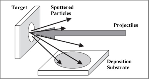 | Figure 1. Schematic illustration of the sputtering process [3] |
2. Experimentation
2.1. Fabrication of Monolayers
- Aluminium (Al), Gold (Au), Niobium (Nb), Tungsten (w), Nickel (Ni) and Gadolinium (Gd) metallic elements were used for the deposition of monolayers with the combination of two metals by magnetron sputtering method. Magnetron sputtering instrument was used at Swinburne University of Technology, Victoria, Melbourne, Australia. The DC magnetron sputter was from Kurt J Lesker (KJL Company, Pittsburgh, PA-USA). The photograph of magnetron sputtering instrument is shown in Fig. 2.
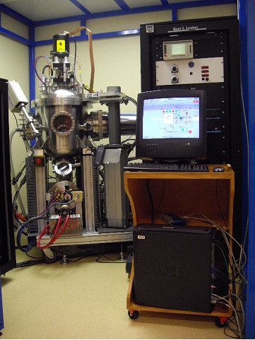 | Figure 2. Photograph of magnetron sputtering instrument |
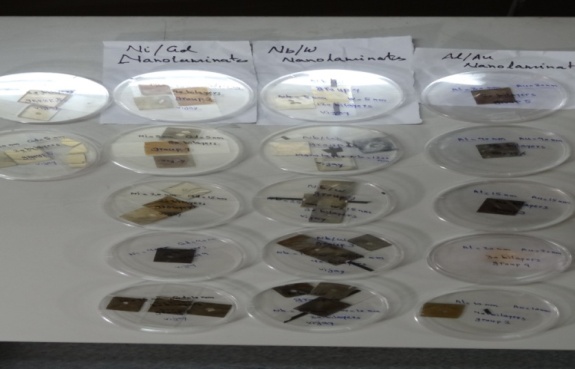 | Figure 3. Different monolayers composite specimens of Al/Au, Nb/w and NI/Gd |
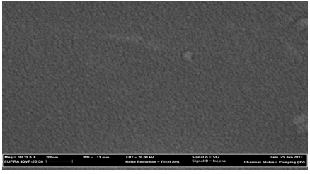 | Figure 4. SEM images showing the uniform coating of monolayer |
2.2. Reciprocating Wear and Friction Test
- Wear and coefficient of friction was measured from reciprocation sliding wear and friction monitor instrument (TE-200ST). The wear and friction test of monolayer composite specimen was performed against sliding flat surface of cylindrical (10 mm diameter) brass pin (Fig. 5a) with receiprocating frequency of 3.3Hz. The total stroke length was fixed 3mm for all tests. The wear and friction results were conducted for 10 min at a normal load 50N as shown in Fig. 5b. The variation in coefficient of friction and sliding temperature were obtained from the machine itself. Finally, the wear loss was measured with the help of electronic digital balance.
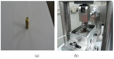 | Figure 5. (a). Cylindrical brass pin and (b) Photograph of reciprocating wear test set-up |
3. Results and Discussion
- Friction test was performed on the reciprocating friction monitor instrument. While performing reciprocating wear test on monolayers composite, it was observed that the nanolayer wear out once brass pin slides over monolayer composite as shown in Fig. 6.
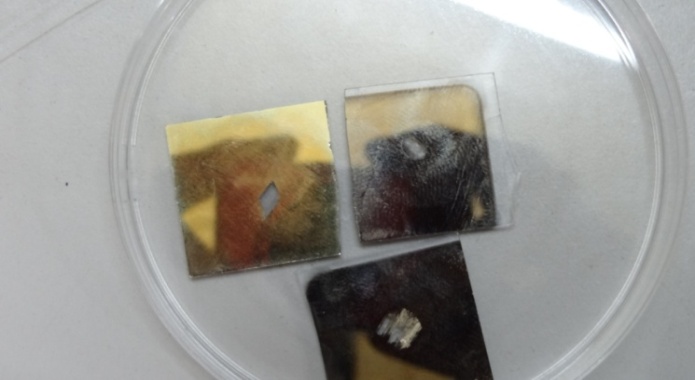 | Figure 6. Wearout surfaces of Al/Au, Nb/w and Ni/Gd monolayer composite |
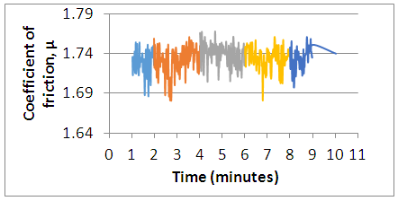 | Figure 7. Variation of coefficient of friction versus time of Nb/w monolayers at constant load 50N |
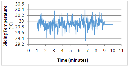 | Figure 8. Variation of sliding temperature versus time of Nb/w monolayers at constant load 50N |
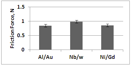 | Figure 9. Variation of friction force with different monolayer composites |
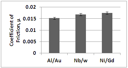 | Figure 10. Variation of coefficient of friction with different monolayer composites |
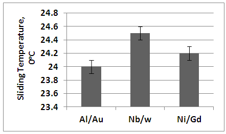 | Figure 11. Variation of sliding temperature with different monolayer composites |
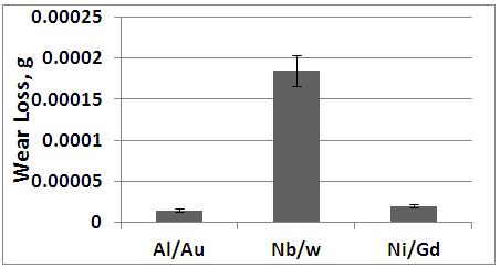 | Figure 12. Variation of wear loss with different monolayer composites |
4. Description
- When two sliding surfaces come into contact, normal and tangential forces are transmitted through the contact area. The debries of the softer surface are easily deformed and fractured by repeated loading. The smooth surface is generated, either when these debries are deformed or removed from the softer surfaces. Once the surface becomes smooth, the contact is not an asperity-asperity contact. The surface traction occurred by the hardner asperity on the softer surface, which includes plastic deformation due to accumulation of repeated loading. Since, brass is sliding over the multi-monolayer composites in which brass surface is softer than the monolayer surface. In this case ploughing occurs because both sliding surfaces have different hardness. The harder surface penetrates the softer surface during the sliding, which produces microgrooves in the presence of asperities. Therefore, extra force is required to resist the ploughing action. Generally, this stage is occurred when large number of wear debries entrapped within the interface remains constant. The ploughing and deformation are contributed to the friction coefficient. However, asperities of monolayers (Al/Au) and brass surfaces are gradually removed and creating a mirror finish, which decreases the friction force, friction coefficient and wear loss because of the decrease in ploughing of the surfaces by the wear particles and the reduction of surface asperities. These reflect that wear loss, friction force and friction coefficient of Al/Au monolayers are less than the Nb/w and Ni/Gd monolayer composites. Therefore, the sliding temperature of Nb/w and Ni/Gd is higher than the Al/Au nanolaminates.
5. Conclusions
- The magnetron sputtering method was successfully used for the deposition of 30 bynanolayer of Al/Au, Nb/w and Ni/Gd materials. These monolayers composite were examined to qualify the wear and friction behaviour against sliding surface of brass. The results indicate that the wear loss, friction force and friction coefficient of Al/Au monolayers are attributed lower values compare to Nb/w and Ni/Gd monolayers, when monolayer specimen surfaces are sliding over the brass surface. The results demonstrate that the particles of aluminum, gold and brass are softer materials, which reduce the wear and friction propeties because of the mirror like surface finish and reduction in surface asperties than the niobium, tungsten, nickel and gadolinium materials.
ACKNOWLEDGEMENTS
- The authors would like to thank Department of Mechanical Engineering, Indian Institute of Technology (BHU), Varanasi-221005, India, and Faculty of Science, Engineering & Technology, Swinburne University of Technology, Victoria, Australia for their support. This research work was supported under the bilateral international research project programme in between India and Australia through Australia-India Strategic Research Fund (AISRF).
 Abstract
 Reference
 Full-Text PDF
 Full-text HTML