Engr Ekundayo Gbenga
Department of Mechanical Engineering Technology, Rufus Giwa Polytechnic, Owo, Nigeria
Correspondence to: Engr Ekundayo Gbenga, Department of Mechanical Engineering Technology, Rufus Giwa Polytechnic, Owo, Nigeria.
| Email: |  |
Copyright © 2016 Scientific & Academic Publishing. All Rights Reserved.
This work is licensed under the Creative Commons Attribution International License (CC BY).
http://creativecommons.org/licenses/by/4.0/

Abstract
Composite materials has come of age, therefore efforts must be completely put in place to ensure that each materials properties and their physical appearance could be enough to predict their reliability in any service conditions. Looking at the initial capital involvement in advance composite production for subsequent use for engineering components with it distinct reliability in strength, lightweight, corrosion resistant, thermal and electrical conductivity etc. The widely use and acceptability of advance composite materials in space and aerospace industries and recently as structural materials with a deep concern about the risk involve, has made composite manufacturing and testing for reliability an imperative aspect of the composite design study. Before now, composites are commonly tested for its reliability and quality control through the use of destructive testing methods but it has been the concerns of researchers to look for alternative method(s) so as to reduce materials wastage and save cost while the integrity (quality) of the composite is still maintained. Hence, the author of this paper manufactured CFC laminates using Carbon/epoxy prepreg material and investigates its reliability with the use of electromagnetic device (Eddy current) a non-destructive device commonly used for the conventional materials (metals). The samples were later destroyed using a velocity impact machine (destructive device) and the damaged samples were also investigated. The results of the two scanned samples were later developed into solid form using the MatLab software and the compared models shows that without destroying the composite, its integrity can be ascertained and even when in- service conditions defects in it can be detected for immediate maintenance or replacement so as to achieve effective cost saving of the composite during and after manufacture.
Keywords:
Composite materials, Manufacturing, Composite maintenance, Destructive test, Non-destructive test, Eddy Current testing
Cite this paper: Engr Ekundayo Gbenga, Using Non-Destructive Testing for the Manufacturing of Composites for Effective Cost Saving: A Case Study of a Commercial Prepreg CFC, International Journal of Materials Engineering , Vol. 6 No. 2, 2016, pp. 28-38. doi: 10.5923/j.ijme.20160602.02.
1. Introduction
Although, the concept of composite is not human but natural, example is wood, naturally made of cellulose fibre with good strength and stiffness. According to Bryan (1999), materials are combined (composite) in such a way as to enable us make better use of their virtues while minimising to some extent the effects of their deficiencies. Ekundayo (2012) opined that materials are processed into useful shapes with their structures and properties optimized to meet the purpose of their selection using the knowledge of science and technology to arrive at a definite shape (manufacturing). Composite, according to Daniel, Suong, and Stephen (2002), revealed that, it is a material that is different from the homogeneous materials but it comprises of materials having strong fibres (continuous or non-continuous) surrounded by a weaker matrix. Therefore, like any other heterogeneous materials composite must be tested for defects free during and after production moreso that composite materials, have become the dominant materials in the field of engineering as its application has grown steadily, penetrating and conquering new market as its uses today are applicable to all engineering producing materials most especially the most sensitive areas like aircraft. There are many methods of manufacturing materials to acquire the desired shapes or forms such as casting, consolidating, machining, folding etc. Sometimes, defects are introduced to materials during production process, or when processing the materials from their raw states (fibre or matrix), and/or during in-service conditions, hence composite materials must be tested to be able to predict and prevent failures as a result of shock, impact or repeated cyclic stresses that can cause the laminated materials to separate at interface between two layers (delamination). The widely involvement of composite in the production of most important structural components of aerospace, auto industries, machineries, medical industries etc, demands that adequate and periodic tests are carried out on them before and during service to ensure that the materials did not deviate from the original design. The two major ways of materials testing are the Destructive testing and the Non-destructive testing. The destructive tests could cost a lot as materials tested could not be used again after tests. In this paper, the author manufactured composite laminates of four and eight layers of stacking sequences of 0o and 90o using carbon/epoxy prepreg (fibres already impregnated in a controlled resin), cured in a Pressure Clave and tested for defects using Eddy Current (electromagnetic machine), a non- destruction testing device, these products were later destroyed using Velocity Impact Testing machine and Eddy Current test were also carried out on the damaged samples to allow for effective comparison.
1.1. Composite
Composite (Composite materials) simply gave indication of the vast range of individual combination that are included in this class of materials. Robert (1999) described composite as an indication that two or more materials are combined on a macroscopic scale to form the third materials. Ekundayo (2012), articulated composite as engineering materials made of two or more constituent materials with significant different physical and chemical properties which remain separate and distinct on a macroscopic level within the finished structure. While Daniel, Suong and Stephen (2002), opined that, composite materials are materials that are indifferent from common heterogeneous materials but the materials are made up of strong fibres-continuous or non- continuous surrounded by a weaker matrix materials. The matrix serves as distributor to the fibres and transmit load to the fibres.Composite materials can be sourced from two major sources, that is, the natural fibers and the synthetic (man-made) fibers. The natural fibers are those from plants, animals and mineral sources while the synthetic fibers are those from the bye-Petrol chemical resources. Fibers generally are in filaments of different geometry (length and diameter). The synthetic fibers which form the raw materials used in this research can appear in different forms such as continuous, discontinuous or in particulate form and as a prepreg fibers (already impregnated with matrix) (Ekundayo, 2012).According to Pop and Bejinaru (2010) and UMESCO (2011), the advantages of using composite materials for engineering component production is enormous compared to the use of the conventional metals as adjudged from their high specific strength and stiffness, impact resistance, corrosion resistance, flexibility and ability to carry loads due to their anisotropic and orthotropic properties with limitations only on cost, temperature, solvent or moisture attack and invisible impact damage, hence, the reason (s) why periodical tests are required to maintain the design properties of the composite when in the service conditions (About.com, 2014).Matrix (resin) is from two major sources, that is the thermosetting matrix and the thermoplastic matrix commonly used among them are: epoxies, polyurethanes, Phenolic, polyamides, Bismaleimides (BMI, polyimides) and the amino resins. Although in the advanced composite design, the use of thermosetting matrix has predominated due to their unique advantages over the thermoplastic matrix such as low viscosity which often encourages adequate fiber wetting and minimum operational temperature is required for curing, hence prevents the fiber from degradation during processing coupled with its resistance to environmental conditions. The matrix acts as a binder that glues the fiber together and keeps them in their respective positions so that they act as individual entities during load sharing and protect them from mechanical damages.Peter (2011) opined that the choice of resin and fiber for a particular composite with regards to stiffness, strength, heat resistance, cost, production rate and methods of manufacturing depends on the designer’s experience. Hence, composite manufacturing process depends on the type (s) or form (s) of fiber and the matrix chosen, the temperature required to form the part and cure the matrix and the cost effectiveness of the chosen method (s).There are many methods of composite manufacturing processes such as: hand lay-up, spray lay-up, filament winding, Pultrusion moulding, resin transfer moulding, autoclave, compression moulding, vacuum bag moulding and infusion processes. Each chosen method has its advantages and limitations but the basic process for composite production involves the following steps: a. Preparation of mould/formb. Pre-impregnation of matrix (Prepreg fiber)c. Carrying out fiber laying in the mould/formd. Applying resin if not already preprege. Curing of composite in the oven (autoclave or vacuum bag)f. Remove cured composite from the oven and carry out trimming.During any of these processes, flaws can be mistakenly introduced to the composite and the resultant effect of this would be production of weak composite that will operate below the design expectations since composite is a combination of two or more elements with the fiber dispersed in the matrix phase. Hence, the materials are expected to be combined to produce a material with enhanced properties other than the individual properties of the combined element (Ajay, 2011). According to Marilena et al, (2010), the strength of composite structure can be affected by two separate defects that is , the imperfection or flaws from manufacturing of the laminate or assembly of the structure and the damage resulting from handling, installation, or in- service conditions (moisture attack). Therefore, Qiuyun (2011), said that the safety and reliability of composites materials largely depend on the design of the composite and manufacturing process in which compression and tension failure often occur and that defect of any kinds and sizes can be introduced to composite materials during manufacturing which will adversely affect the performance of the component.However, composite materials have become more increasingly used in the Aerospace, building, Marine, Sport industries due to their unique properties of strength/weight ratio, corrosion resistance and ability to form any complex shape. Thus, if flaws are unknowingly introduced to the composite materials made up of these equipment / machines during any of these processes; fibers processing, matrix, during manufacturing and in-service conditions, the resultant failure can be disastrous.To maintain excellent balance between quality control and cost effectiveness, non- destructive testing of the composite materials using the non-destructive equipments commonly used in the maintenance of the conventional metals during and after manufacturing is obligatory since the materials or the properties of the materials would not be altered (protecting procurement costs of composite materials believed to be more costly at the initial stage than the conventional metals) during this process and the material can still be used if satisfied okay.
2. Non-Destructive Testing
Non- destructive testing as the name implies means carrying out test on components to correct inconceivable or assumed defects which could lead to the poor performance of the component (s) as against the designers’ initial aims of its design without necessarily rendering the material(s) or component useless. It is a non-invasive technique of determining the integrity of materials, components or structures since it allows for inspection of materials without interferences in its final use.Warren (1969) simply explains non-destructive tests as those tests which permit testing or inspection of materials without prejudice to its future usefulness.Waldemar (2008) described non-destructive testing as methods being used for detecting defects in materials and evaluation of materials properties without causing changes to their usable properties. Qiuyun (2011) opined that non-destructive tests are carried out on materials without damaging them and that is an excellent balance between quality control and cost effectiveness. Waldemar (2008), in his consideration for reasons why composite materials defects are better detected using non-destructive testing, said composite materials have various structures and that any damage to these materials are more complicated other than what it used to be on metals and the reasons why some of the methods and diagnostic techniques used in metals cannot be 100% relied upon when used for composite materials. NDT methods are used with aims of locating and characterising materials conditions and flaws capable of causing plane crash, reactors failure, train derailment, pipe bursting and a variety of less visible but capable of threatening both lives and properties (IAEA, 2005).However, there are six NDT methods that are used most often. These methods are: visual inspection, liquid Penetrant testing, magnetic particle testing, electromagnetic or eddy current testing, radiography, and ultrasonic testing. Although, each method has its merits and demerits but in this research the reliability of eddy current, an electromagnetic devices commonly used for defects detection was put to tests using CFRP of various thicknesses with and without defects.
2.1. Eddy Current (Electromagnetic Testing, ET)
Electromagnetic testing (ET) of materials relies on the principle of forming an alternate current around a specimen, hence, generating an induce current closely to the surface of the specimen. History has it that in 1824, Fancios Arago (1786-1853) detected rotator magnetism and observed that every conductive material has the potentiality of being magnetised. This was later buttressed with Michael Faraday laws of magnetic induction (1791-1867) and in 1834, Heinrich Lenz stated Lenz’s law saying that, “the direction of induced current flow in an object will be such that its magnetic field will oppose the magnetic field that cause the current flow”. This is the principle so established in ET for Non-destructive testing of materials, components or structures. In 1879, David Hughes became the first person to use ET as NDT when he used it to conduct metallurgical sorting tests and subsequently it became effective tool for materials testing during the Second World War and in the aircraft and nuclear industries. Eddy Current method is based on the principle of measuring changes in the impedance of an electromagnetic coil as it is scanned over a surface of conductive material.The test is performed by an electromagnetic coil (Probe, figure 2) that is placed over a conductive material (figure 1). The coil produces a magnetic field that is induced in the material. To counter the coil's primary magnetic field, eddy currents are produced in the material. Eddy currents produce a secondary magnetic field that will oppose the coil's primary magnetic field. When the coil is placed over a defective point during scanning, the secondary magnetic field is distorted thereby changing the loading on coil which will affect directly the coil impedance. These changes in coil impedance are related to the defects such as crack or any discontinuity in the tested sample.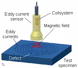 | Figure 1. Principle of eddy current testing (Adopted from: Federal Institute of material and Testing, 2012) |
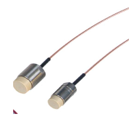 | Figure 2. Types of Absolute Probes (Single Coil) (Adopted from: Waycon, 2012) |
The probe can appear in different forms aside from the absolute type mentioned above such as Differential probe, reflection probe and hybrid probe; they can be customized to meet specific purpose.
2.2. Eddy Current Operational Principle
The principle of operation for Eddy current is basically on the measurement of the differences between the changes in the impedance of an electromagnetic coil when used to scan over the surface of a conductive material.The probe (electromagnetic coil) is placed over the conductive material to be tested, the coil produces a magnetic field that is induced in the material hence to counter the coil primary magnetic field and eddy current is produced in the material. The eddy current produces a secondary magnetic field that will oppose the coil primary magnetic field. Thus, when the coil is placed over a defective point during scanning, the secondary magnetic field is distorted therefore, the change in the load on the coil impedance are related to the defects such as crack or any discontinuity within the tested materials.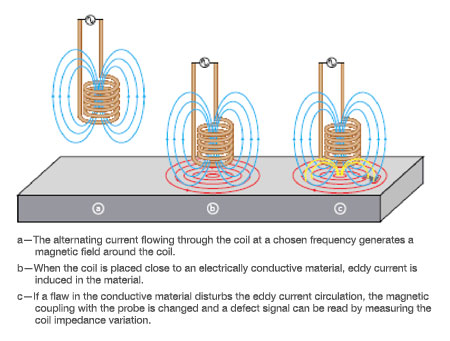 | Figure 3. Showing what happened when eddy current comes in contact with test piece( Adopted from:Tom and Cynthia, 2011) |
According to the NDE Association (2012), the major factor that can affect the performance of eddy current is the depth of operation and this had been described to be inversely proportional to the square root of the conductivity of the material, frequency and its permeability. This is mathematical expressed as: Where
Where  is the conductivity of the material,
  the magnetic permeability (1 for non ferrous magnetic material and less than 1 for ferrous magnetic materials) and
  specifying the frequency of inspection (Qiuyung, 2011).
3. Destructive Testing
Destructive tests are the tests carried out on materials until the material fails; this is the types of test carried out in order to understand a material’s structural behaviour under different loads. The purpose of destructive testing is to determine the service life and detect design weakness that may not show up under normal conditions. One of the major advantages of destructive tests is that it is easier to carry out and interpreted compare to NDT and much more economical when carried out on mass produced materials (this cannot be said of Batch products).There are many destructives tests that can be carried out on materials to determine their integrity to resistance such as shock or impact loads. According to Instron (2012), testing like: Bending, Compression, Creeping or Stress relaxation, Fatigue, Flexure, Hardness, Impact, Rhenology, Shore, Tensile and Torsion are all destructive when performed on materials.Impact testing is the test carried out on materials to determine the resistance of the material to velocity impact loads. It is used to determine the maximum energy a material can absorb before it fails when affected with high velocity load. Impact testing is a very important tests in determine the service life of materials. It has become a major problem for the designers nowadays that the safety of lives and properties are very and highly important. In composite materials impact damages are sometimes difficult to quantify. Hence , impact test can be used to predict the expected energies that the material may likely face during its life time, or the type of impact load and the energy that will deliver the load that can cause fracture so as to be able to develop a material that resist these forces. Pendulum and Drop weight are the two major ways of carrying out impact testing on materials. The pendulum with a known weight is swing under the action of force of gravity and hit a vertically positioned specimen, hence the energy lost and the one absorbed during the action can be calculated.In this research the drop weight type was adopt to create defect, here the material is clamped at the bottom of the impact machine, the expected weight to drop is clamped vertically in the direction of the clamped specimen, with help of the machine rail ,the weight is expected to fall freely in the direction of the unit under test. Once the height and the weight are known, the energy can be calculated. The results from the test can be easily analyzed. According to Instron (2012), this can be done by either accepting the material or rejecting it using the pass/failure mode. But in this research the Instron is only used to create defect so as to be able to simulate the composite debris when affected by drop loads. The advantages of drop weight over other methods made reliable such as:● It can be used for moulded samples● It is unidirectional with no preferential to direction of failure, the weakest part failed first and move to other parts● Materials does not need shattered before failure can be determined.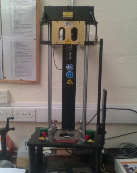 | Figure 4. Impact Machine, drop weight ( Adopted from: UoB. 2012) |
3.1. Why Impact Testing Composite Materials
According to Neil Hancox (1996), one of the greatest advantages of fibre reinforced composite materials are their widely used in space and aerospace sectors where their low density, coupled with durability, stiffness and strength has make them an attractive weight saving option, the same properties had drawn the attention of other industries to the used of composite hence, there must be enough information about their properties and performance so that they can continue to gain full acceptance of engineer and designers. The recent involvement of composite materials in the structural applications coupled with fact that safety have become a major priority, therefore, it has become very imperative that manufacturers should have adequate information on how the materials they are sending out would perform under crash conditions, they must be primarily tested under similar expected service condition before being released to customers.
4. Composite Manufacturing
Peter (2011) expressed the view that to choose from the various methods of composite manufacturing processes, it depends on the type of fibers and matrix chosen, the curing temperature to form the part and the cost effectiveness of the chosen process. According to Pop and Bejinaru (2010), composite manufacturing can be grouped based on functions of construction hence they can be divided into laminates and sandwiches. Ever (1998) and Sanjay (2002) said that the choice of manufacturing process depends on the production rate/speed, performance, size and the final shape of the material. Although, Ever (1998) expressed the fact that the various manufacturing processes differ in their ways of operation but agreed that they are all executed following the basic manufacturing steps with the expression that some processes are done simultaneously like the case of filament winding where the fiber placement, impregnation and consolidation are done at the same time meanwhile in the case of prepreg, the impregnation had been done prior to their being used.According to Pandey (2004), composite manufacturing can be summarily grouped into three categories:● Open Mould processes● Close mould Processes● Continuous processesIn this paper, the open mould process is adopted that is the hand lay-up moulding process using the prepreg lay-up method. Here, the prepreg were cut and laid in 0° and 90° fiber orientations in the male and female plate mould and rapped with silver foils to prevent leakage of resin. Thereafter, the composite with the mould is placed inside the oven or autoclave. Heat and pressure are then applied for the curing and consolidation of the part.
5. Experimental Procedure
5.1. Materials Selection
The material used for this research is a commercial prepreg of Carbon/epoxy (AS4 8552), supplied to the University of Bolton from Hexcel Manufacturer of composite and kept inside a deep freezer at a shelf life of -18°C (LINEO, 2012).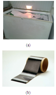 | Figure 5. a. The Carbon/epoxy prepreg inside the deep freezer. b. A tape of the UD prepreg covered at the back with white silicon paper |
Prepreg are often supplied as unidirectional or woven fabric but in this research the unidirectional prepreg of CFRP (AS4 8552) made of carbon fiber already pre-impregnated with perfect controlled of epoxy resin was used. The property of the CFRP prepreg as supplied by the Hexcel Manufacturer of composite is as shown below.Table 1. Mechanical properties of Carbon/epoxy prepreg AS4 8552
 |
| |
|
5.2. Preparation of Composite Laminates
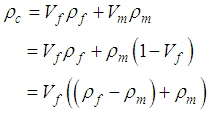
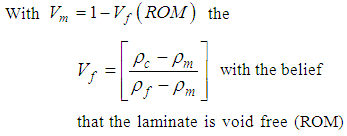
Basically, designers are very conscious when choosing materials for a particular purpose as they often design against failure. In the composite designs, after chosen the appropriate fiber and resin that have the required properties needed for the purpose of choosing them, the designers are very careful not to introduce defects into the composite during manufacturing. The mathematical model commonly used for the prediction of composite materials mechanical properties is called the rule of the mixture (ROM). The rule obeys some assumptions although used with caution but can be used to determine the volume fraction, weight fraction and the density of the composite which is the density and volume fraction of each of the constituents of the materials selected (Larry et al, 2012). It can also be used to determine the quantity, the plies arrangement (orientation) and the geometry of the composite (thickness, shape and methods of arriving at them: production). | (1) |
Where  various Volume fraction of the plies and
  is the density of the various plies
 | (2) |
 | (3) |
or from the known weight faction of the fiber  thus,
thus, | (4) |
and the composite laminate thickness can be calculated using the below formula Although, the properties of the chosen prepreg has been indicated in (Table 1).The CFRP prepreg was cut to piece with each plies having 200 x 200 x 0.19mm of 0° unidirectional orientation and two samples were manufactured from them with sample A having four (4) layers and sample B having eight(8) layers. A polished aluminium alloy plate of dimension 300 x 300 x5mm was used as mould. The mould was first cleaned with Acetone liquid to remove dirt or dust from mould surface and it was coated with release agent for easy removal of samples from the mould after curing.
5.2.1. Laminates Manufacturing
The two samples were laid within the mould with first sample containing 4 layers of stacking sequences of (0O/90O)2S and the second sample made of 8 layers of stacking sequences of (0O2/90O2)2s on the mould and rapped with silver foils before being placed inside the pressure clave for curing.
5.2.2. Curing Process
The mould was placed inside the heating chamber of the Pressure Clave and closed with a constant pressure of 10kg/cm2 and the recommended curing temperature of epoxy resin was maintained. The Pressure Clave has pressure gauge and pyrometer, the pressure gauge was used to set the pressure at the constant pressure of 10kg/cm2 and the pyrometer which have upper and lower limit temperature gauge to allow for the temperature variation and error correction of plus or minus 10°C. The upper gauge was set at the correct recommended curing temperature while the lower gauge was set at less than 10°C of the recommended temperature. Hence, at every interval the gauge maintained 60°/50°C for the first one hour and 120°/110°C for another one hour and lastly 180°/170°C for two hours (figure 7). This was constantly maintained for the two samples used for this research and the cooling hours with laminate still inside the heating chamber is two hours after which the composite sheet are removed.  | Figure 6. (a) Release agent, (b) Polished aluminium plate, (c) A cut to size CFRP prepreg lamina |
 | Figure 7. (a) Laid layers of CFRP (0°/90°/90°/0°), (b) Closed mould with laminate, (c) Pressure Clave |
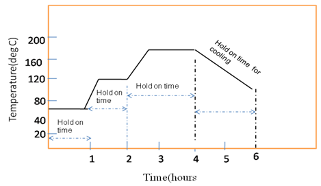 | Figure 8. Curing and cooling curve for the CFRP composite sheet |
Table 2. Measured and calculated physical properties of the cured laminates
 |
| |
|
5.3. Tests Analysis of the Samples Using ET and Mat Lab
The two samples were properly dressed up to 200 x 200 mm and later cut each into two samples of 100 x 100mm. Each sample was meshed into 10 x 10mm (figure 9) and the Eddy current device set-up with the probe as displayed below (figure 10) is made up of the Eddy current circuit, the amplifier, the monitor and the probe. The Eddy current probe used for this research is Probe no.3 (Absolute probe). | Figure 9. Cured laminate of sample 1 & 2 with sample 1 made up of 4 layers and sample 2 made up of 8 layers with thickness of 0.96mm and 1.69mm respectively |
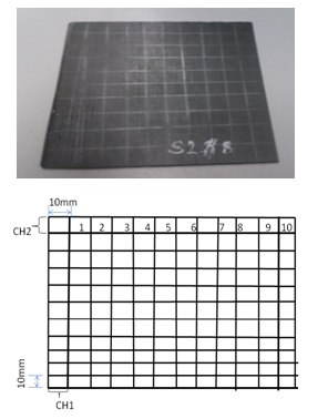 | Figure 10. Meshed laminate CFC sample for Eddy current scanning |
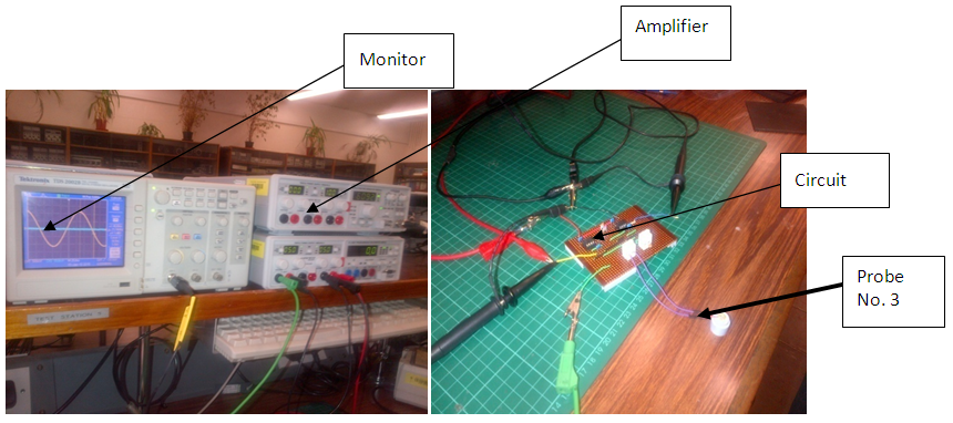 | Figure 11. Eddy current NDT machine set up for scanning |
5.4. Experimental Procedure
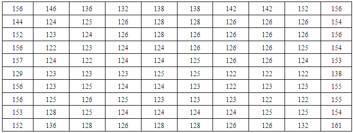
After properly connected, the NDT (EC), the voltage channel of the eddy current is regulated for example for this research it was regulated to 300mV, hence the output value is noted with the unit also in mV. The meshing of the samples into 10 x 10mm was to take care of the edge effect. However, each meshed sample was then placed on a based board and scanned with the probe checking each meshed point. In this research, each point was scanned for five times and the average taking was recorded as their output results due to each tested sample.Table 3. Voltage output recorded during the scanning for defect in one of the samples (mV). Just immediately after manufactured
 |
| |
|
The figures were later fractionalised called normalized output voltage of the probe. Here the edge effects were taken into consideration and the meshed output voltages were reduced to 8 x 8 data points.Table 4. Normalized output voltage of the 8 x 8 data points (mV)
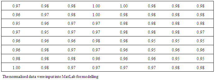 |
| |
|
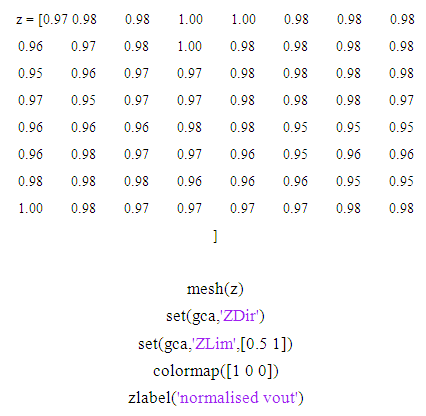 | Figure 12. MatLab Model of the normalized result from the Eddy current |
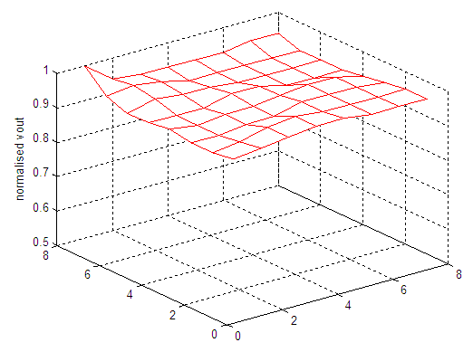 | Figure 13. Outcome of the MatLab modelling of the sample’s voltage output |
The same sample was later destroyed using the velocity impact machine named Instron Dynatup having blue hill software, drop weight impectum, cable of acceleration measurement software. 3.915g weight, 9J (energy), 9.81m/s2 acceleration due to gravity, and at the height of 234mm was adopted for the testing of this sample.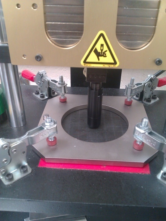 | Figure 14. Showing how the impectum strike the sample |
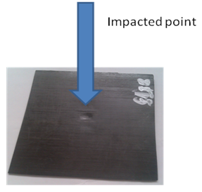 | Figure 15. The impectum striking point (front) |
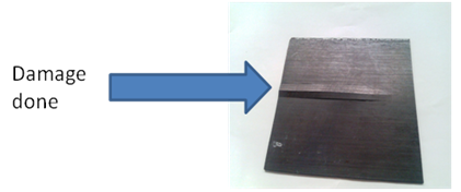 | Figure 16. The damage done at the opposite side of the CFC |
Hence, the same scanning process was carried out on the destroyed samples and the voltage output was also modelled as shown below.Table 5. Show the Voltage output recorded during scanning for defects after destruction of the sample and the Normalized output voltage (mV)
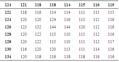 |
| |
|
Table 6. Show the Voltage output recorded during scanning for defects after destruction of the sample and the Normalized output voltage (mV)
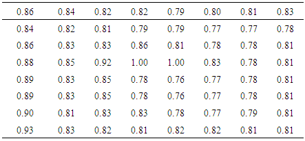 |
| |
|
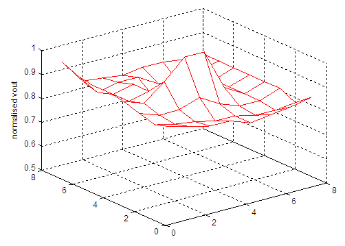 | Figure 17. Outcome of the MatLab modelling of the sample’s voltage output |
The MatLab of the defective sample as shown above revealed that the cone like shape at the centre of the model shows where the damage occur and extended along the axis of the defect compare to figure 12 where no visible defect was displayed.
6. Conclusions
● The production after scanning shows no internal defect, this was confirmed from the MatLab model carried out as shown in figure 13 meaning that the manufactured composite is devoid of any defect(s). ● Eddy current shows its reliability as a non-destructive, low - cost and high value instrument that can be used to detect defect(s) in composite for quality control with effective cost saving as demonstrated from the scanning results after been manufactured and when destroyed using velocity impact machine and the displayed MatLab results in figure 13 and figure 17.● The physical behaviour of the composite after being affected by velocity impact load as demonstrated with the use of impact machine (figure 14, 15 & 16), shows that the inside and the back of the composite are affected more than the point at which the velocity load hit the composite vis-a-vis figure 16 have shown the reason why NDT test is necessary intermittently why in use. Hence a regular NDT test is recommended for CFC during and after or in in-service conditions.● Although, Eddy current, a non-destructive testing equipment is considered to be a reliable low cost, high valued, portable and easy to use in any field of applications compare to use of Ultrasonic C-scan but can only be used for conductive materials (National Instrument, 2012).
ACKNOWLEDGEMENTS
I am sincerely indebted to the following people who assisted me in the actualization of this paper; they are Prof. Peter Myler, Mr Brian Pederson, and Dr. Erping Zhou from university of Bolton, UK and Miss Qiuyun Sang, Mr. Akbar Zarei, Mr. Shahram Shafiee all from the University of Bolton composite Laboratory.
References
| [1] | Ajay Kapadia. (2011). Non-destructive testing of composite materials [online] Available from: <http://www.compositesuk.co.uk/LinkClick.aspx?fileticket=14Rxzdzdkjw%3D&tabid=111&mid=550> [Accessed 16 February, 2012] |
| [2] | Ekundayo, G. (2012) Using non-destructive testing of commercial prepreg for the manufacturing of composite. M.Sc dissertation, School of Built Environment and Engineering, University of Bolton, Uk. |
| [3] | Daniel Gay, Suong V. Hoa and Stephen W. Tsai (2003) Composite materials: design and applications, CRC Press LLC, Paris. |
| [4] | Peter, Myler (2012) Introduction to composite [online] Available from: <MSc Composite Module>, [Accessible 18 February, 2012]. |
| [5] | Ever J, Barbero (1998), Introduction to composite materials design, Taylor & Francis. |
| [6] | IAEA (2005) Non-destructive testing for plant life assessment (online) Available from: <http://www-pub.iaea.org/mtcd/publications/pdf/tcs-26_web.pdf> [Accessed 23 January, 2012]. |
| [7] | Qiuyun Sang (2011). An investigation of NDT technology in composite. MSc thesis, University of Bolton, school of Built Environment and Engineering, UK. |
| [8] | Robert M. Jones (1999). Mechanics of Composite Materials (2nd Ed) Taylor & Francis, Ltd, London. |
| [9] | Sanjay K. Mazumdar (2002). Composites manufacturing materials, products, and process engineering. Library of cataloguing-in-publication data, USA. |
| [10] | Wikilipedia (2012) Laminate [online]. Available from: <http://encyclopedia2.thefreedictionary.com/Composite+laminates> [Accessible: 11th Janunary, 2012]. |
| [11] | Waycon, (2012) [online]. Available from: η(http://www.waycon.biz/uploads/tx_piwaycontable/1325/tx_wirbelstromsensor.jpg > [ Accessible: 27 March, 2012]. |
| [12] | Larry D. Peel, Vishwajit, Grudge and Dustin Grant (2012) Introduction to upward bond [online]. Available From: <http://www.slideserve.com/hova/introduction-to-upward-bound> [Accessed 2nd March, 2012]. |
| [13] | Instron (2012). Impact testing, [online]. Available from: <http://www.instron.co.uk/wa/applications/test_types/impact/default.aspx> [Accessed 1st April, 2012]. |
| [14] | Composite materials handbook (2002) polymer matrix composites Vol.5, Department of Defence Handbook, USA. |
| [15] | About.com (2014) omposite/Plastic: fibre Volume [online] Available from: <http://composite.about.com/library/glossary/v/bldef-v5986.htm> [Accessed 15 March, 2015]. |
| [16] | Bryan, H. (1999). Engineering composite materials, Institute of materials, London. |
| [17] | Pop, P. Adrian and Bejinaru, Mihoc Gheorghe (2010) Manufacturing process and application of composite materials, Journal of Fascicle of management and technical engineering, Vol.9 (19), University of Oradea. |
| [18] | Advance Composite Group (UMESCO, composite). (2011). Introduction to advance composites and prepregs technology [online]. Available from: <www.advanced-composites.co.uk/.../sm1010-...> [Accessed 16th January, 2012]. |
| [19] | National Instrument Developer Zone (2012) Ultrasonic Non-destructive Testing - Advanced Concepts and Applications [online]. Available From: <http://zone.ni.com/devzone/cda/tut/p/id/5369> [Accessed 24th March, 2012]. |
| [20] | Neil Hancox (1996). Impact testing of composite of the automotive industry. Material World [online]. 1(40), pp203206. Available from: <http://www.azom.com/article.aspx?ArticleID=744> [ Accessed 12th march, 2012]. |


 Where
Where  is the conductivity of the material,
  the magnetic permeability (1 for non ferrous magnetic material and less than 1 for ferrous magnetic materials) and
  specifying the frequency of inspection (Qiuyung, 2011).


 various Volume fraction of the plies and
  is the density of the various plies

 thus,
thus,
 Although, the properties of the chosen prepreg has been indicated in (Table 1).The CFRP prepreg was cut to piece with each plies having 200 x 200 x 0.19mm of 0° unidirectional orientation and two samples were manufactured from them with sample A having four (4) layers and sample B having eight(8) layers. A polished aluminium alloy plate of dimension 300 x 300 x5mm was used as mould. The mould was first cleaned with Acetone liquid to remove dirt or dust from mould surface and it was coated with release agent for easy removal of samples from the mould after curing.


 Abstract
 Reference
 Full-Text PDF
 Full-text HTML


