International Journal of Materials Engineering

p-ISSN: 2166-5389    e-ISSN: 2166-5400

2016;  6(1): 15-21

doi:10.5923/j.ijme.20160601.03


Numerical Study of Finite Fracture Growth in an Epoxy Resin

André Luis Christoforo1, Márcio Eduardo Silveira2, Avelino Manuel da Silva Dias3, Victor Almeida De Araujo4, Francisco Antonio Rocco Lahr5

1Department of Civil Engineering, Federal University of São Carlos (UFSCar), São Carlos, Brazil

2Department of Mechanical Engineering, Federal University of São João del-Rei (UFSJ), São João del-Rei, Brazil

3Department Mechanical Engineering, Federal University of Rio Grande do Norte (UFRN), Natal, Brazil

4Research Group LIGNO of UNESP-Itapeva, Department of Forest Sciences, School of Agriculture Luiz de Queiroz of University of São Paulo (ESALQ/USP), Piracicaba, Brazil

5Department of Structural Engineering, Engineering School of São Carlos (EESC/USP), São Carlos, Brazil

Correspondence to: André Luis Christoforo, Department of Civil Engineering, Federal University of São Carlos (UFSCar), São Carlos, Brazil.

Email:

Copyright © 2016 Scientific & Academic Publishing. All Rights Reserved.

This work is licensed under the Creative Commons Attribution International License (CC BY).
http://creativecommons.org/licenses/by/4.0/

Abstract

In the last decades, the study of fracture mechanics has been increase as tool capable to analyze the mechanical strength for structures without the occurrence of failure. The presence of small cracks can reduce the structural strength of the component enabling, in some cases, the collapse of the structure under a lower stress than the structural ultimate strength. Currently, the use of numerical methodologies, as finite element method (FEM), that address the problem of fracture in structural components to representing the macroscopic regime of the structure has been also used becoming increasing. The goal of the article, through the analysis of fracture and grounds of FEM, determine the fracture growth for a polymeric material (epoxy resin). Through ASTM E399 were established experimental procedures for obtaining fracture toughness (GC), the mechanical fracture bending SE (B) testing was choose, for its simplicity of design and manufacture. Three different numerical models were used to analyze the behavior the material and the fracture process. The results obtained from the numerical simulation were close to the literature results, confirming the effectiveness of the numerical tool used in predicting fracture phenomena in the material and its evolution associated with the loads application.

Keywords: Fracture, Finite Element Method, Epoxy resin

Cite this paper: André Luis Christoforo, Márcio Eduardo Silveira, Avelino Manuel da Silva Dias, Victor Almeida De Araujo, Francisco Antonio Rocco Lahr, Numerical Study of Finite Fracture Growth in an Epoxy Resin, International Journal of Materials Engineering , Vol. 6 No. 1, 2016, pp. 15-21. doi: 10.5923/j.ijme.20160601.03.

1. Introduction

In the last decades, the fracture mechanics field has undoubtedly prevented a substantial number of structural flaws. If it is correctly applied, the fracture mechanics inhibits the flaws from the negligence during the project and of that due to the implementation of new projects with the utilization, or not, of new materials, which produce an unexpected and unwanted result in their behavior [1]. In these recent decades, new methods approach the problem of these structural failures through the numerical models with macroscopic organization of the structure [2-5]. More recently, discrete models of finite elements have been used along with the concepts of fracture mechanics, continuum mechanics and finite fracture mechanics by the evaluation of the structure damage [3, 6-8]. These approaches have been developed for both the analysis of structural flaws in ceramics, metals, polymers and, more recently, the composite materials. However, the correct incorporation of mechanical and phenomenological aspects inherent to failure mechanisms become dominant for success and effectiveness of such predictive methodologies applicable to numerical analysis of the mechanical integrity of a wide class of structural components and different material types [3, 9]. In this regard, over the years, the finite element method (FEM) has established itself as a simulate and study the nucleation and crack growth in the structures. The FEM include simple procedures for extrapolation of the stress intensity factor and the development of special elements (decohesion elements) for cracks to represent the failure region, as well as the stress in the crack’s front or tip [3, 6-10].
This study aimed to evaluate the behavior of cracks or areas prone to damage in a polymeric material (epoxy resin) through different numerical models enabled for the study of fracture problems. It is noteworthy that the epoxy resin is a commonly used material as matrix phase in the development of various composites [4]. It was used a commercial software of finite elements, and three different analysis for study development were used [10]. Thus it is intended to contribute to the understanding of numerical techniques for determining of the behavior of process failures, enabling an improvement in the safety of structural projects.

2. Material and Methods

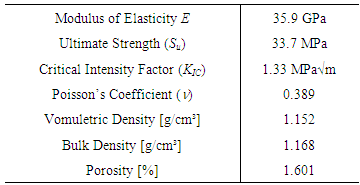
Table 1 presents the data obtained in the literature for the mechanical behavior of commercial epoxy resin. This raw material has long been used as matrix phase of particulate composites and, in particular, the laminated composites of glass fiber, aramid fiber and carbon fiber. The latter composite material has been extremely used in the aerospace industry due to its excellent relation between mechanical strength and its weight (density). However, due to the mechanical characteristics of the matrix and of disperse phase, this composite has a fragile mechanical behavior. Therefore, it is possible to apply the mechanical concepts of linear elastic fracture to then study the other damage numerical models available on finite element solver [10].
Table 1. Mechanical Properties of Epoxy Resin [11, 12]
     
ASTM E399 [13] prescribes experimental procedures to be adopted in the tests to validate Critical Stress Intensity Factor (KIC). A popular mechanical test of fracture is the mechanical fracture bending at three points or SE (B), for its ease of design and manufacture, mainly in materials with fragile behavior. Another factor that is related to the selection of the SE (B) test was the easy in the preparation of models and meshes for the numerical simulation developed in this work [14].
Figure 1 illustrates the geometry and dimensions in millimeters adopted for the specimen SE (B). In this figure, S is the length between the specimen supports, B is its width, W is its height and a is the crack size.
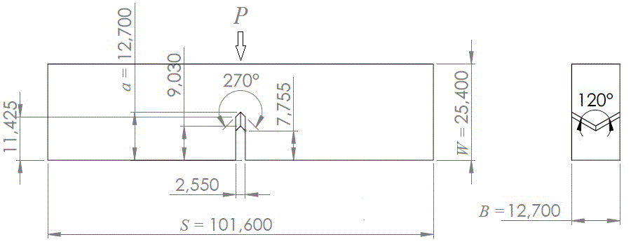
Figure 1. Illustration of the SE (B) specimen with dimensions in millimeters [13]

2.1. Linear Elastic Fracture Mechanics Model (LEFM)

As can be seen in Medeiros et. al. [3], the concept of linear elastic fracture mechanics prescribes, for the tests with SE (B) specimens, some relationships between the mechanical properties of the material and geometrical properties of the specimen. In addition, as a condition for validation of this test, there is the need to ensure the existence of a plane condition of deformations at the crack tip, and these conditions are evaluated by Equation 1 [1, 3]. In this numerical simulation, KQ value corresponds to the critical stress intensity fator KIC material [13, 15].
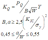
(1)
Thus, it was possible to find the value of external load P, applied in the middle of span (S) to reach the condition of crack growth, which could be stable (ductile material) or unstable (fragile material).
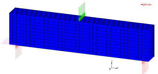
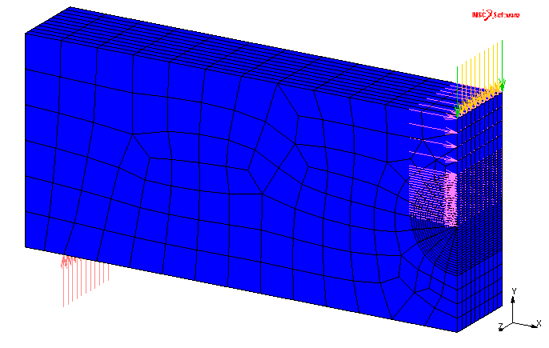
Figure 2. 3D mesh of numerical model of SE (B) specimen considering ½ symmetry. 3.550 solid elements (3D) with eight nodes were used
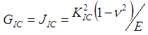
Figure 2 shows the mesh used in the three-dimensional model to represent the SE (B) specimen of bending test, considering the ½ of sample due to its symmetry. As Marc™ software [10] calculates the value of toughness fracture (GIC) in front of the crack through the integral J (JIC), it was necessary to determinate their experimental value from critical stress intensity factor (KIC) of the epoxy resin using the Equation (2). This expression is valid within the linear elastic fracture mechanics regime, and considering the plane strain conditions [1, 3, 13, 15]. In Figure 2, it is also shown the refinement shape of the mesh in front of the crack, ensuring the numerical singularity able to adequately represent the singularity of the stress field at the crack tip, in accordance with the analytical formulation of fracture mechanics [1].
(1)
In this study, SE (B) bending test, its numerical model and the critical intensification stress factor of the epoxy resin were used to verify the crack nucleation and growth through the other numerical models.

2.2. Cracking Strain Model

To incorporate the numerical simulation to some mechanisms to examine fracture process, initially, constitutive relationship based on classic models of continuum mechanics was used, Figure 3, which was also known as cracking strain model [16, 17]. This model assumes an elastic behavior to the breaking point of studied material or critical cracking stress (σcr). After reaching this limit, it is estimated that its damage is characterized by a cracking strain of the material in the normal direction to the maximum principal stress (Rankine theory) and the material is replaced by an orthotropic behavior (references). This model allows the incorporation of a reduction behavior in the strength of the structure after the formation of first crack, described by a parameter of tension-softening modulus (ES).
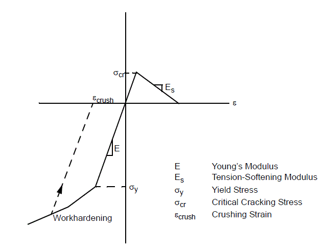
Figure 3. Uniaxial Stress-Strain Diagram for Cracking Strain Model [10]
This model of cracking strain presents good overall results when the crack area is restricted to small dimensions if it is compared to the structure size [15-17]. Some materials present mechanical behavior that resembles to this model of cracking strain, e.g., the epoxy resin. Recently, the evaluation of failures in laminated composites has also used similar models to this damage [7, 9].
The analysis used the same 3D mesh previously defined, including their simplifications and boundary conditions (Figure 1). However, the evolution of cracks in the structure of the model of cracking atrain results in a reduction of its load carrying capacity, and the field of internal stresses should be redistributed to regions where there are no failures. Making this numerical simulation a nonlinear analysis, this brings about the need of the interactions use to achieve the convergence of the numerical analysis. Therefore, it was used fifty increments in this numerical procedure. The parameter of tension-softening modulus (ES) of the epoxy resin was estimated at 1/10 of its modulus of elasticity or Young´s modulus (E), according to the literature [15, 17].

2.3. Virtual Crack Closure Technique Model (VCCT)

Another way to study the crack growth is the direct approach, or fracture mechanics approach. This approach directly utilizes fracture mechanics criteria in which the strain energy release rates (G`s) are computed and compared to the corresponding critical valor, for example, fracture toughness in mode I (GIC). Recently, the virtual crack closure technique is the most popular and powerful tool to approximately computes G`s values, specially, because VCCT is simple, efficient and robust in analyzing any crack growth problems [8]. Instead of the fact that these analyses almost have a very expensive computational cost.
Figure 4 shows the 3D mesh used in this analysis, which is able to represents the SE (B) specimen, whereas their dimensions were shown in Figure 1. Since this analysis was adopted a procedure of automatic generation of meshes during the simulation (automesh), it was opted a first rough mesh, with four hundred 3D solid elements of eight nodes. In addition, the specimen was modeled without taking advantage of its symmetry due to the use of automesh to refine the crack front. In order to a better numerical control during the processing [18], the external load was applied through a prescribed displacement applied in the middle of the span (y). The value of this prescribed displacement was obtained through the first model used here, i.e., through the simulation of fracture mechanics model. Finally, as the crack growth criterion, it was used the value of toughness fracture (GIC) for epoxy resin obtained through the Equation (2). It was used a hundred increments and no convergence difficult has been found during the crack growth analyses.
Figure 4. 3D mesh initially used in VCCT analysis for the numerical model for specimen SE (B) with 400 3D solid elements with 8 nodes

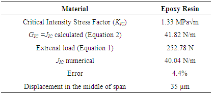
3. Results and Discussions

Table 2 shows the results obtained by numerical simulation using the mechanical model of linear elastic fracture showed in Figure 2. The external load applied in bending specimen SE (B) was P = 252.78 N.
Table 2. Numerical results from LEFM analysis for Epoxy Resin
     
This value was determined from the replacement of the mechanical properties showed in the Table 1 in Equation 1, considering the geometric dimensions of the specimen showed in Figure 1. Whereas in this analysis it was used ½ of the specimen SE(B) due its symmetry, the external load applied was P/2. The results showed that this simulation represented the behavior of the epoxy resin during the test with SE(B) specimen, because the difference between the numerical value of integral J with its experimental (JIC) was 4.4%. A major advantage of this method is its low computational cost associated with a rapid solution to be a linear elastic analysis of the material [3]. Nevertheless, its main limitations are due to the fact of having to include a crack in the model and the attention in the generation of numerical singularity at the tip (2D) or in front of the crack (3D). This difficulty has been the subject of many studies published in the literature [3, 19]. In a complex structural design is not always possible to identify crack location and its growth direction, as well as the facility to adequately model the singularity at the tip or in front of the crack. This difficult becomes almost insurmountable when it is studied the fracture mechanisms in laminated structural composites [9].
The second model tested was diffuse crack. Despite the use of the same mesh of the previous LEFM model, one of the advantages of this model is the no need of attention with the singularity at the tip or in front of the crack, as can be seen in some studies [15, 17]. After the parameter of tension- softening modulus (ES) has been estimated as 10% of the modulus of elasticity of the epoxy resin [15], i.e., ES = 3.59 GPa, and considering the critical cracking stress (σcr) as the ultimate strength (Su), i.e., σcr = 33.7 MPa (Table 1), it was simulated the test with specimen SE(B) incorporating the model of diffuse crack in this analysis. Since it also takes advantage of the geometry of the previous analysis with its simplification due to the symmetry of the problem, the external load applied was 126.39 N (P/2).
In Figure 5 were found cracking strain in front of the crack, indicating that this region is critical, whereas cracking strain value was greater than zero (εcr = 8.2x10⁻³). In other words, the maximum principal stress was higher than the value of ultimate strength (breaking point of the material or critical cracking stress), Figure 3, which starts a damage process of the crack front. Simulations with this model has presented a compatible result with the previous analysis and with a low computational cost; despite it is a non-linear mechanical behavior model which can present convergence problems if the simulation presents many damage areas.
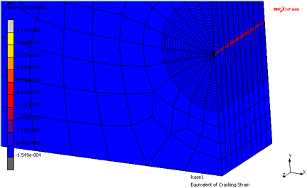
Figure 5. Numerical distribution of equivalent cracking strain in front of crack
This diffuse crack model has good overall results when the crack area is restricted to small dimensions comparing to the structure size [15-17]. Several literature reports show the convergence problems of this model in different studies about fracture mechanisms; since the structural problems studies [7, 14-15], and the studies about thin surface coating [17]. Other advantages of this model have been its use in failures of composites studies [4, 9] and the absence of the knowledge about the critical stress intensity factor (KIC) or toughness fracture (GIC) of the material to test it, i.e., only there is the need to know the breaking point. Last advantage is relevant because fracture mechanics experimental tests are more expensive and more complex if they are compared with tensile tests, especially when the focus is the study of laminated composites [20].
The third model tested was the VCCT (virtual crack closure technique) using automesh process to automatic generation of the mesh during the simulation. In this simulation was adopted the mesh defined in the Figure 4, without the use of simplification to take advantage of the problem symmetry. This coarse mesh would facilitate the first procedure of automesh of commercial program of finite elements [10]. That is, the initial mesh may be relatively coarse in order that the automatic generation processing of the mesh has the advantage to establish the necessary conditions for the representation of the singularity in front of the crack. However, this procedure has a high computational spent, which restrict its use, particularly when it is used in more complex geometries [6, 8, 10].
The external load was applied in the middle of the span through a prescribed displacement aiming to a better numerical control of the convergence during its processing [17-18]. The value of the displacement de y = 35 µm was obtained in the analysis of the LEFM (Linear Elastic Fracture Mechanics model), according to the results in Table 2. The failure criterion adopted was that of strain energy release rate, i.e., toughness fracture. The value of toughness fracture was GIC = 41.82 N/m, obtained by replacing the mechanical properties of epoxy resin of Table 1 in Equation 2.
Figure 6 shows the instant that precedes the first stable crack propagation, in accordance with VCCT model. Esta primeira propagação aconteceu com uma carga inferior ao obtida aplicando-se o máximo deslocamento transversal. At this time, the program refined the mesh, especially in the region of crack front, using a total of 7065 elements. This happened in the 78th increment and the numerical value found for the strain energy release rates (G) was 41.34 N/m. This value is 1.16% lower than the toughness fracture of the epoxy resin.
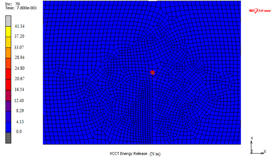
Figure 6. Zoom of the mesh in front of the crack for the VCCT model of the epoxy resin
Figure 7 shows the front of the crack image of the VCCT model in the end of the numerical simulation, i.e., in the hundredth interaction. The numerical value for the strain energy release rate in the end of the analysis (G) was 40.05 N/m, indicating that this specimen was in the imminence to reach its total collapse. This result also shows compatible with the previous analysis, whereas it shows that the crack front is a critical region and it illustrates the growth of this crack, which practically it has its total collapse when the external load reaches the value of maximum load, according to the linear elastic fracture mechanics, applied through a prescribed displacement.
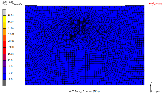
Figure 7. Zoom of the mesh in front of the crack for the VCCT model of the epoxy resin in the end of test
From the point of view of the crack growth analysis, this VCCT model showed an interesting behavior, because it visualize this growth and it was able to indicate a likely growth way of this crack.
These are the advantages of VCCT model in relation to the two models previously tested. In contrast, its computational spent was extremely high comparing to the two previous, which could become impracticable its use in the analysis of the more complex structural problems, e.g., in the aerospace structure study with composite materials [9, 20].
During these studies with these VCCT models there were several problems in the automatic generation of the mesh, especially in 3D models. In contrast, the models did not present difficulties in its convergence, because it was used a prescribed displacement to try to facilitate this convergence, instead of the external load in the middle of the span. Certainly the external load would hamper the convergence and automatic generation processes due to stress concentration in point or line of load applied. But, in structural problems, it is not always possible to apply the external load through a prescribed displacement. This was only possible in this study whereas it was determined the displacement in the LEFM simulation model.

4. Conclusions

A major advantage of the adoption of numerical analysis is in its low cost, but with great precision, speed and reliability, in addition to reduce the spent time in the experimental tests performance of the same style. However, these analyses require a high knowledge of the concepts related to the methods and analytical and numerical models [21]. Therefore, this research aimed to study the fracture processes in epoxy resin through its numerical simulation. In this study, three different numerical models were adopted to evaluate a fracture mechanics test defined by ASTM E399 standard [13]. The selected test was the bending at three points SE (B) due to its ease of numerical modeling and because it is widely used in the analysis of ceramic materials, polymers, and recently laminated composites.
The first simulated model was the linear elastic fracture mechanics, through the calculation of the Critical Stress Intensity factor (KIC) of the epoxy resin found in the literature (Table 1). In the numerical analysis, the integral J was used to evaluate the model, whereas it is the parameter adopted by the finite elements software [10]. The numerical model was able to represent the SE (B) test, as well as reproduce the singularity in the region in front of the crack. The difference between the numerical value of JIC and experimental was 4.4%. This analysis showed quickly, because the material presented a linear elastic behavior. However, its main limitations are due to the attention in the generation of the numerical singularity in front of the crack.
The second tested model was of cracking strain model. In the numerical simulation of SE (B) was possible to verify that this analysis represented the mechanical behavior of the experimental test, whereas the region in front of the crack reached the breaking point when they were given in the maximum load defined by the linear elastic fracture mechanics (Figure 4).
The last model tested was the VCCT with the utilization of the automesh process during the simulation. This model showed the crack growth with more precision, which may be used to simulate the nucleation process of this crack. The initial mesh can be relatively rough, considering that the numerical processing with automesh establishes the necessary conditions for the representation of the singularity in front of the crack. However, the high computational spent in this model makes its use somewhat restricted, if it is compared to previous models.
Finally, all analyzed models were able to represent the mechanical behavior of specimen in the bending test SE(B). Despite the specialized literature presents several studies using different models of finite element in numerical simulations [5], rarely is found a same work about the comparison of failure mechanisms studies. Comparing the three studied models in termos of difficulties in the mesh generation and computational costs, it can be concluded that the diffuse crack model was able to simulate the mechanical behavior of the test SE(B) and to capture the characteristics of the formation of cracks during these conventional tests of fracture mechanics. This model also presented a low computational cost when is compared with the powerful VCCT model. Therefore, it is recommended to adopt this model in bi modularity in the first step in the structural design process to identify areas prone to nucleation and growth of cracks. Then, an upgrade could occur in the simulation including the VCCT model, but restricting and directing in the critical areas defined in the simulation with the bi modularity model. The importance of the LEFM model would limit to validate the studies in the cases when there were difficulties in the obtaining mechanical properties derived from complex mechanical tests [20].

ACKNOWLEDGEMENTS

The authors recognize the National Council for Scientific and Technological Development (CNPq) for financial support through process 460943/2014-6. One of them also thanks for the CAPES (Higher Coordination for Scientific and Educational Training), through process BEX 6569-14.

References

[1]  Anderson T.L., Fracture Mechanics, Fundamentals and Applications, third edition, CRC Press, Inc., 688p (2004).
[2]  Cornetti, P., Pugno N., Carpinteri A., Taylor D.: Finite Fracture Mechanics: A Couple Stress and Energy Failure Criterion, Engineering Fracture Mechanics, 73, 2021-2033 (2006). <doi:10.1016/j.engfracmech.2006.03.010>
[3]  Medeiros E. E., Dias A. M. S., Christoforo A. L.: Numerical Simulation of Mechanical Fracture Testing, International Journal of Materials Engineering, 2 (5), 61-66 (2012). <doi:10.5923/j.ijme.20120205.01>
[4]  Vogler M., Rolfes R., Camanho P.P.: Modeling the Inelastic Deformation and Fracture of Polymer Composites – Part I: Plasticity Model, Mechanics of Materials, 59, 50-64 (2013). <http://dx.doi.org/10.1016/j.mechmat.2012.12.002>
[5]  Alfonso I., Rodríguez-Iglesias V., Figueroa I.A.: Computational Potentialities of the Finite Elements Method for the Modeling and Simulation of Composite Materials: A Review, Matéria, 20 (2), 293-303 (2015). <http://dx.doi.org/10.1590/S1517-707620150002.0030> [in Spanish]
[6]  Davila C.G., Camanho P.P., Rose C.A.: Failure Criteria for FRP Laminates, Journal of Composite Materials, 39, 323-345 (2005). <doi: 10.1177/0021998305046452>
[7]  Turon A., Camanho P.P., Costa J., Dávila G G.: A Damage Model for the Simulation of Delimitation in Advanced Composites under Variable-mode Loading, Mechanics of Materials, 38, 1072-1089 (2006). <doi:10.1016/j.mechmat.2005.10.003>
[8]  Xie D., Biggers Jr, S.B.: Progressive Crack Growth Analysis Using Interface Element Based on the Virtual Crack Closure Technique, Finite Elements in Analysis and Design, 42, 977-984 (2006). <doi:10.1016/j.finel.2006.03.007>
[9]  Camanho P.P., Erçin G.H., Catalanotti G., Mahdi S., Linde P.: A Finite Fracture Mechanics Model for the Prediction of the Open-hole Strength of Composite Laminates, Composites: Part A, 43, 1219-1225 (2012). <http://dx.doi.org/10.1016/j.compositesa.2012.03.004>
[10]  Msc. Marc, Volume A: Theory and User Information. Users Manual, MSC. Software Solutions Download Centre. In: http://www.mscsoftware.com (2015).
[11]  Callister Jr. W.D., Ciência e Engenharia de Materiais, 5a Ed., LTC (2002). [in Portuguese].
[12]  Matweb, In: http://www.matweb.com/search/MaterialGroupSearch.aspx (2015).
[13]  ASTM (American Society for Testing and Materials), E399 - Standard Test Method for Plane-Strain Fracture Toughness of Metallic Materials, 512-532 (1999).
[14]  Miranda J. S., Christoforo A. L., Dias A. M. S.: Determination of the Mechanical Behaviour of a Ceramic Glass Composite by Finite Element Method, International Journal of Researches and Reviews in Applied Science, 13 (2), 428-435 (2013). <www.arpapress.com/Volumes/Vol13Issue2/IJRRAS_13_2_06.pdf>
[15]  Chaves Filho, O. F., Gabriel S. Medeiros G.S., Pereira Segundo A.A., Dias A.M.S., Christoforo A.L.: Simulation of the Fracture Process Through a Damage Model in Different Materials, International Journal of Researches and Reviews in Applied Science, 23 (3), 233-240 (2015). <www.arpapress.com/Volumes/Vol23Issue3/IJRRAS_23_3_07.pdf>
[16]  Oller S., Fractura Mecánica: um enfoque global, CIMNE, Primera Edición, 286p (2001). [in Spanish].
[17]  Dias A.M.S., Sotani P.F.B., Godoy G.C.: Simulation of indentation testing in thin films using numerical cracking models, Matéria, 15 (3), 422-430 (2010). <http://dx.doi.org/10.1590/S1517-70762010000300005> [in Portuguese]
[18]  Dias, A. M. S., Modenesi, P. J., Godoy, C., Computer Simulation of Stress Distribution During Vickers Hardness Testing of WC-6Co, Materials Research, 9 (1), 73-76 (2006). <http://dx.doi.org/10.1590/S1516-14392006000100014>
[19]  R. D. Henshell, K. G. Shaw. Crack Tip Finite Element Are Unnecessary, International Journal for Numerical Methods in Engineering, 9, p495-507 (1975)
[20]  P. P. Camanho, G. Catalanotti. On the Relation between the Mode I Fracture Toughness of a Composite Laminate and that of a 0o Ply: Analytical Model and Experimental Validation, Engineering Fracture Mechanics 78, p2535-2546 (2011). <doi:10.1016/j.engfracmech.2011.06.013>
[21]  Camanho P.P., Turon A., Lopes C.S., Trias D., Technical Report: Best Practice Analysis Methods, European Space Agency, Jun 2010.