Ekerete Affiah , Cynthia Nwaeju, Eugene Nnuka
Materials and Metallurgical Engineering Department, Nnamdi Azikiwe University, Awka, Nigeria
Correspondence to: Ekerete Affiah , Materials and Metallurgical Engineering Department, Nnamdi Azikiwe University, Awka, Nigeria.
| Email: |  |
Copyright © 2016 Scientific & Academic Publishing. All Rights Reserved.
This work is licensed under the Creative Commons Attribution International License (CC BY).
http://creativecommons.org/licenses/by/4.0/

Abstract
Aluminium-4%wt copper alloy being a 2xxx series alloy, exhibits moderate strength as a result of needle-like structure of the intermetallic compound (Al2Cu(θ)) formed as non-coherent precipitates as the alloy cools slowly to ambient temperature. Hence, this paper focuses on addition of refractory oxides to melted Al-4%wtCu alloy, in order to refine the grain size and structure, thereby improving the mechanical properties of the alloy. The objective of this work is to study the extent to which each concentration of the oxides influenced the mechanical properties of Al-4%Cu alloy and the concentrations that gave an appreciable mechanical property suitable for engineering application. The experiment was carried out by adding refractory oxides in concentrations of 0.75%, 1%, 1.25%, 1.5%, 1.75%, 2% and 2.25% by weight to melted Al-4%Cu alloy, stirred and sand cast. Mechanical tests and micro-examination were carried out and the results established that the refractory oxides can be used to improve the microstructure and mechanical properties of Al-4%Cu alloy.
Keywords:
Refractory Oxide, Mechanical Properties, Al-4%Cu Alloy
Cite this paper: Ekerete Affiah , Cynthia Nwaeju, Eugene Nnuka , The Impact of Refractory Oxides on the Structure and Mechanical Properties of Al-4%Cu Alloy, International Journal of Materials Engineering , Vol. 6 No. 1, 2016, pp. 1-7. doi: 10.5923/j.ijme.20160601.01.
1. Introduction
Aluminium alloys have been utilized for more than a century [13]. The combination of strength, low density, formability, corrosion resistance, conductivity and abundance nature makes the material ideal for a number of applications [6] [14]. The alloys have high strength-to-weight ratio and durability which makes them useful for foil and conductor cables [5] [12]. Both the automotive and aerospace industries benefit greatly from the high strength-to-weight ratio of aluminium alloys [7] [11]. The heterogeneous nature of aluminium alloys is most evident in members of the high strength alloys of the 2xxx, 6xxx, 7xxx and 8xxx and most particularly the 2xxx series alloys where additives are required to obtain the high strength to weight ratio properties of these materials [1] [12]. Besides, aluminum on its own is a great thermal conductor, making it highly applicable for heat transfer systems, including heat exchangers and cooling ribbons [7]. It is the third most abundant element, it forms about 80% of the earth’s crust, exist in the form of aluminosilicate or aluminum oxide called bauxite as a result of its high affinity for oxygen and silicates [6]. Aluminum is ductile and malleable due to its polycrystalline structure [4] [8]. According to Cochran and Maphother, it is capable of being a superconductor with a superconducting critical temperature of 1.2 Kelvin and a critical magnetic field of about 100 gauss (10 milliteslas) [3]. Owing to its resistance to corrosion, aluminum is one of the few metals that retain silvery reflectance in finely powdered form, making it an important component of silver coloured paints [4]. Al-4%Cu alloy is distributed in form of individual isolated inclusions between the dendrite cell and grain boundary [10]. The increase in hardness and tensile strength is due to the interaction of the stress field around the particles with a moving dislocation and also due to physical obstruction by the hard particles to the moving dislocation [5] [6]. The extent to which strengthening is produced depends on the amount of the second phase particles, the characteristics and properties of the second phase, the particle size, shape and distribution [10] [2]. Aluminium-4%wt copper alloy being a 2xxx series alloy, exhibits moderate strength as a result of needle-like structure of the intermetallic compound (Al2Cu(θ)) formed as non-coherent precipitates as the alloy cools slowly to ambient temperature [9]. Hence, this paper focuses on addition of refractory oxides to melted Al-4%wtCu alloy, in order to refine the grain size and structure, thereby improving the mechanical properties of the alloy. To produce Al-4%wtCu alloy with improved mechanical properties, the concentration of the oxides was varied in the order of 0.75, 1.0, 1.25, 1.5, 1.75, 2.0 and 2.25%wt, in Al-4%Cu alloy. The extent to which each concentration influenced the mechanical properties of Al-4%Cu alloy was studied and the concentrations that gave an appreciable mechanical properties suitable for engineering application was established.
2. Main Body
2.1. Methods
The refractory oxides were added in concentrations of 0.75%, 1%, 1.25%, 1.5%, 1.75%, 2% and 2.25% by weight to melted Al-4%Cu alloy, stirred and sand cast. Subsequently, specimens obtained from the casting were subjected to machining and mechanical properties such as ultimate tensile strength, hardness, yield strength, ductility and impact strength were determined for each specimen using Mansanto tensometer, Rockwel hardness tester and universal impact testing machine, respectively. The microstructure of the samples was also studied using metallurgical microscope and PRO-X model SEM machine, with photographs taken.
2.2. Experimental Procedure
2.2.1. Charge Preparation
The materials to be charged into the furnace were prepared according to the following processes:357g of aluminium scrap taken as 96wt% and 14.892g of copper scrap taken as 4wt% were weighed using a portable electronic weighing balance. Similarly, for 0.75wt%, 1wt%, 1.25wt%, 1.5wt%, 1.75wt%, 2wt% and 2.25wt% of (CaO, MgO, SiO2 and Cr2O3, each), the equivalent in grams weighed, were 2.74g, 3.65g, 4.56g, 5.48g, 6.39g, 7.30g and 8.21g respectively.
2.2.2. Mould Preparation
The mould was wooden comprising of a cope and drag and the sand used was green sand, mixed with bentonite as the binder. With the aid of a cylindrical pattern, an impression was made on the sand which served as a cavity to contain the hot molten alloy to be poured for solidification. The sand was rammed, and the runners and the risers were equally made as well as vent. Eventually, the pattern was removed along with the wood used for making the risers and the mould preparation was completed.
2.2.3. Melting and Casting
The weighed scraps and oxide compositions were melted in a crucible furnace in the following order:357g of aluminium was first poured into a metallic crucible (cup), immersed in the furnace and heated in order to melt at 670°C. The melted aluminium was stirred during which 14.892g of copper was added and the copper melted at 1083°C. Digital multimeter was used for measuring the temperature during casting. Finally, 2.74g of CaO was added and further stirred for homogeneity of the mixture. As homogeneity was achieved, the cup was removed from the furnace and poured into the cylindrical cavity of a prepared green sand mould and was left there for 3 to 5 mins, for solidification to take place. Similarly, the casting process was repeated for 2.74g of (SiO2, MgO and Cr2O3), 3.65g of (CaO, SiO2, Cr2O3 and MgO), 4.56g of (CaO, SiO2, Cr2O3 and MgO), 5.48g of (CaO, SiO2, Cr2O3 and MgO), 6.39g of (CaO, SiO2, Cr2O3 and MgO), 7.30g of (CaO, SiO2, Cr2O3 and MgO) and 8.21g of (CaO, SiO2, Cr2O3 and MgO). A control sample, comprising only 357g of aluminium scrap and 14.892g of copper scrap was equally casted. Eventually, each casting was recovered from the mould after solidification, and was allowed to cool in air.
2.2.4. Machining
The machining operation was carried out using a three jaw chulk lathe machine. The samples to be machined were firmly clamped on the machine and facing, turning and shaping operation was done on the clamped samples with the aid of a cutting tool, mounted on the tool post of the lathe machine. Eventually, the required dimensions for impact, tensile and hardness tests as well as microstructural analysis, were obtained.
2.3. Mechanical Tests
2.3.1. Tensile Test
Standard tensile test specimens, having an original guage length of 28mm and diameter of 5mm were used for this test. The tensile test was therefore conducted using horizontal bench - top Mansanto tensometer and the test was carried out at room temperature. The specimens (three samples on each composition) were tested to determine their ultimate tensile strength, yield strength and ductility (%EL). These properties were determined and the average results were as tabulated in table 2.1a and table 2.1b.
2.3.2. Hardness Test
Hardness of the specimens was determined using TESTOR HT 1 Otto Wolpert-Werke Rockwell hardness testing machine. The hardness test was conducted with a 15kg indentation - 100kg scratching scale. Three readings were taken for each specimen at different locations to circumvent the possible effect of any alloying element segregation and the average value was recorded. With the aid of a standard conversion table, the Rockwell hardness test results were converted to Brinell hardness test values which were tabulated as shown in Table 2.1a and 2.1b.
2.3.3. Impact Test
Impact test was carried out with Samuel Denison - LS10 2DE impact testing machine and the test was done at standard organization of Nigeria (SON). The charpy impact test samples were machined to a dimension of (10Х10Х 55) mm with a v-notch of depth 2.5mm at its midpoint. The samples to be tested were placed at the machine’s sample post with the notch facing the hammer and the hammer was raised to an angle of 45° and released to swing through the positioned sample in order to break it. As the samples were broken by the swung hammer, the impact energy absorbed was read from the charpy impact energy scale, calibrated in Joules. Therefore, the impact energy of all the samples, as well as the control sample were captured and tabulated in table 2.1a and 2.1b.
2.4. Micro-Structural Examination
The following steps were taken for micro-structural examination of the as-cast specimens:
2.4.1. Cutting
The specimens were cut to mounting size with the aid of a hack saw.
2.4.2. Mounting
The cut specimens were mounted on a thermosetting material.
2.4.3. Grinding
The mounted specimens were ground using P220C, P320C, P600C, and P800C grades of water-proof Silicon carbide grinding paper (sequenced from coarse to fine).
2.4.4. Polishing
The ground specimens were polished using ECOMET II polisher, after pouring diamond paste on the rotating polishing surface of the ECOMET II polishing machine. This was done to remove the fine surface scratches on the specimens in order to have mirror-like finish.
2.4.5. Etching
The polished specimens were etched with Keller’s reagent to expose the specimens’ surface for micro-structural examination. It was further rinsed in water and dried with METASER specimen dryer.
2.4.6. Micro-Structural Examination
The etched and dried specimens were finally subjected to micro-structural examination using an optical microscope, after which the micrographs of (×100) magnification were obtained with the aid of a digital camera linked to a computer, for a visual display of the snapshots.
2.5. Results
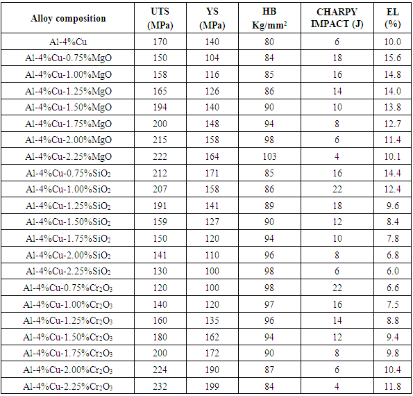
Result on the effect of dopants of 0.75%wt - 2.25%wt concentrations, on mechanical properties of Al-4%Cu alloy are shown in table 2.1a and table 2.1b.Table 2.1a. The Effect of Dopants on Mechanical Properties of Al-4%Cu Alloy
 |
| |
|
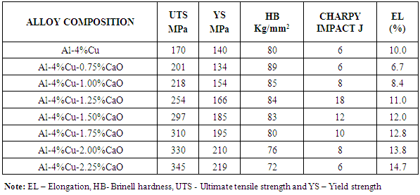
Table 2.1b. The Effect of Dopant (CaO) on Mechanical Properties of Al-4%Cu Alloy
 |
| |
|
2.6. Discussion of Results
From figure 2.1 it was observed that the percentage elongation of the control specimen was lower than that produced when it was doped with some of the concentration of the dopants. This was noticed with the addition of MgO, CaO, SiO2 and Cr2O3 from 0.75%-2.25%, 1.25%-2.25%, 0.75%-1% and 2%-2.25% concentrations, respectively. It was equally noted that magnesia with 0.75% had the highest percentage elongation among the dopants.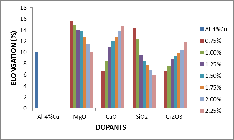 | Figure 2.1. The effect of Dopants on percentage elongation of Al-4%Cu alloy |
Figure 2.2 shows the effect of dopants on the hardness value of Al-4%wtCu. It was observed that the hardness value of Al-4%Cu alloy improved reasonably when the alloy was doped with magnesia (MgO), silica (SiO2), chromium trioxide (Cr2O3) and 0.75%-1.5%CaO. Hardness was seen to decrease with increased in concentration of CaO beyond 1.5%.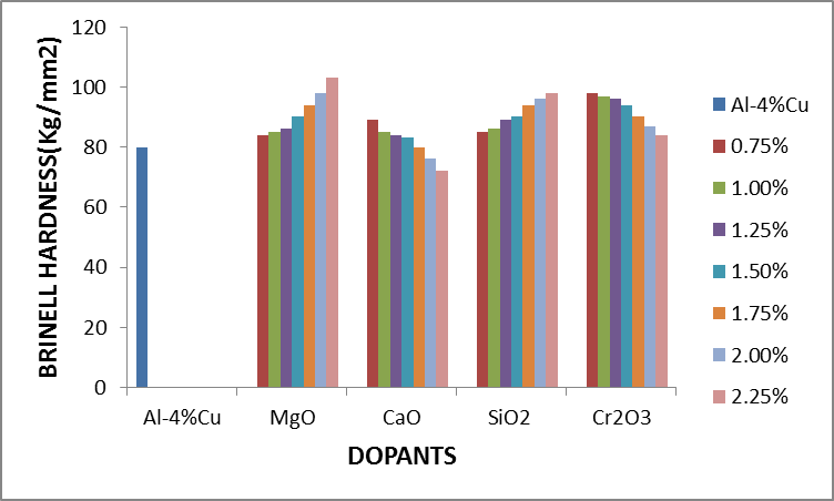 | Figure 2.2. The effect of Dopants on Hardness of Al-4%Cu alloy |
Figure 2.3 shows the effect of dopants on the ultimate tensile strength of Al-4%Cu alloy. From figure 2.3, addition of some of the concentration of the dopants improved the ultimate tensile strength of Al-4%Cu alloy. The dopants: magnesium oxide, calcium oxide and chromium trioxide were noticed to improve the ultimate tensile strength of Al-4%Cu alloy as their concentration increased from 1.5%-2.25%, 0.75%-2.25% and 1.5%-2.25% respectively. This was because of an opposition to the dislocation motion caused by either lattice distortion or the formation of an intermetallic compound. Calcium oxide dopant gave the most improved ultimate tensile strength than other dopants as its concentration increased. It was also noticed that the ultimate tensile strength was improved with 0.75% - 1.25% concentration of silicon dioxide.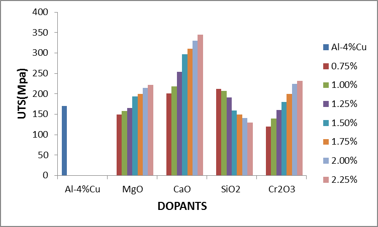 | Figure 2.3. The effect of Dopants on ultimate tensile strength (UTS) of Al-4%Cu alloy |
Figure 2.4 shows the effect of dopants on yield strength of Al-4%Cu alloy. Yield strength of Al-4%Cu alloy improved by the addition of some of the concentration of the dopants as shown in fig. 2.4. The addition of magnesium oxide(MgO), calcium oxide (CaO), silicon dioxide (SiO2) and chromium trioxide (Cr2O3) with concentrations 1.75%-2.25%, 1%-2.25%, 0.75%-1.25% and 1.5%-2.25% respectively, increased the yield strength of the Al-4%Cu alloy.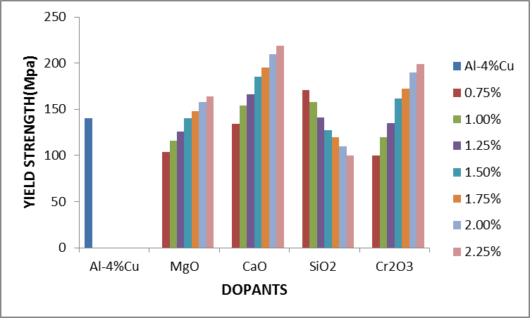 | Figure 2.4. The effect of dopants on yield strength of Al-4%Cu alloy |
Figure 2.5 shows the effect of the dopants on the impact energy of Al-4%Cu alloy. It was observed that MgO with concentrations 0.75% - 1.75%, CaO with 1% - 2% concentrations, SiO2 with 0.75% - 2% concentrations as well as Cr2O3 with 0.75% -1.75% concentrations improved the impact energy of the alloy. It was equally observed that acidic oxides with concentration 1%SiO2 and 0.75%Cr2O3 had the highest impact energy.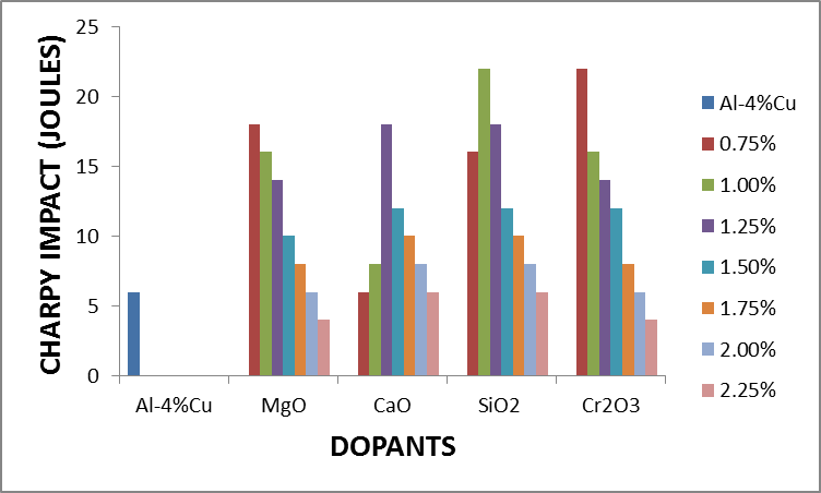 | Figure 2.5. The effect of dopants on impact energy of Al-4%Cu alloy |
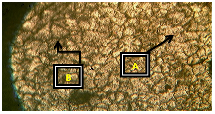
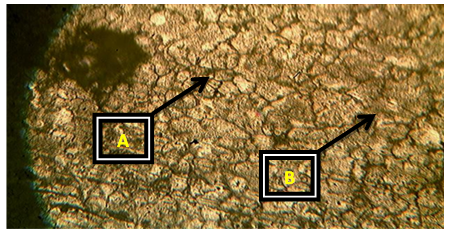
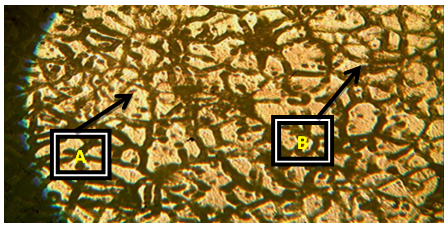
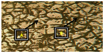
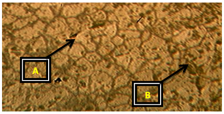
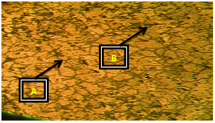
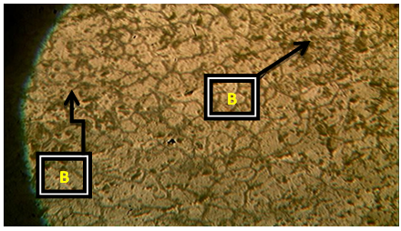
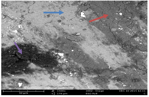
Plates 1-8 represent the micrographs of Al-4%Cu alloy and Al-4%Cu alloy doped with calcium oxide of 0.75%wt -2.25%wt concentrations.Where: A – α-solid solution, B – intermetallic compound.The micrograph and SEM photograph of the control specimen (Al-4%wtCu) shown in plate 1 and plate 9, reveals that the microstructure of the specimen comprised of the eutectic α-solid solution (the region where copper formed a solid solution with the aluminium matrix, which is the grey region in SEM photograph) and the intermetallic compound (Al2Cu precipitates, which is the dark region in SEM photograph). The intermetallic compound existed in the form of coarse need-like precipitate from the α-solid solution by the grain boundaries.Plates 2-8 show the micrographs of Al-4%wtCu doped with calcium oxide of concentrations 0.75%wtCaO to 2.25%wtCaO, while plate 10 shows SEM photograph for Al - 4%wtCu doped with 2.25%wtCaO. The plates show that there was a gradual increase in intermetallic compounds from the grain boundaries, as the concentration of calcium oxide increased. This revealed the possibility of lattice distortion in the alloy system. Hence, a stress field was set up in the alloy matrix and it interacted with the stress field caused by the moving dislocation, thereby giving rise to an increase in ultimate tensile strength and a decrease in hardness beyond 1.5%wt, as the concentration of CaO increased. The plates equally revealed relatively large grains in the matrix, which explains why ductility was improved beyond 1%wtCaO concentration. Plate 10 has three distinct microstructural regions which are: the blue arrow region signifying α-solid solution, followed by the brown arrow region signifying Al2Cu intermetallic phase, and finally, the purple arrow region signifying Al2Cu-CaO intermetallic phase. From plate 10, it could also be seen that the spread of intermetallic compounds in the alloy matrix was limited, which further explains how an increase in CaO concentration improved the ultimate tensile strength and ductility instead of the hardness of the Al-4%wtCu alloy.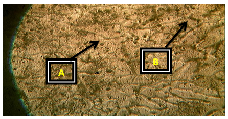 | Plate 1. Al - 4%wtCu (Х100) |
 | Plate 2. Al-4%Cu – 0.75%wtCaO (Х100) |
 | Plate 3. Al-4%Cu – 1%wtCaO (Х100) |
 | Plate 4. Al-4%Cu – 1.25%wtCaO (Х100) |
 | Plate 5. Al-4%Cu – 1.5%wtCaO (Х100) |
 | Plate 6. Al-4%Cu – 1.75%wtCaO (Х100) |
 | Plate 7. Al-4%Cu – 2%wtCaO (Х100) |
 | Plate 8. Al-4%Cu – 2.25%wtCaO (Х100) |
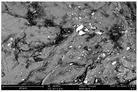 | Plate 9. SEM photograph for Al- 4%wtCu (Х4000) |
 | Plate 10. SEM photograph for Al-4%Cu – 2.25%wtCaO (Х1500) |
3. Conclusions
The results showed that the addition of the refractory oxides at certain concentrations, improved the mechanical properties of Al-4%Cu alloy. The mechanical properties were improved because the refractory oxides could not melt along with aluminium and copper, but remained as dissolved solid particles in the alloy (Al-4%Cu) and serves as nuclei on solidification, thereby refining the grains, modifying the microstructure of the alloy and also restricting the motion of dislocation in the alloy.
ACKNOWLEDGEMENTS
Our gratitude goes to CUTIX Cable Plc., Nnewi and JIMEX Industries Nigerian limited, Nnewi and St. Quality International Company, Onitsha for their assistance in provision of some of the materials used in this research work. Our special thanks go to Mr. Donatus Okele, Mr. Kalu King, Mr. Ifeanyi Kelechi and staff of standard organisation of Nigeria (SON), Enugu who assisted in sample design, melting, casting and mechanical testing of the samples.
References
| [1] | Birbilis N., and Bucheit R. G. (2005) Electrochemical characteristics of intermetallic phases in aluminium alloys, an experimental survey and discussion, Journal of the Electrochemical Society, 152(4):B140-B151. |
| [2] | Bourgeois L., Dwyer C. M., Weyland J. F., Nie and Muddle B. C. (2011) Structure and energetics of the coherent interface between θ’ precipitate phase and aluminium in Al-Cu Acta Mater., 59:7043-7050. |
| [3] | Cochran J. F., and Mapother D.E. (1958) Superconducting transition in aluminium, Physical Review, 111(1):132-142. |
| [4] | Hatch J. (1984) Aluminium Properties and Physical Metallurgy, Metals Park, OH: American Society for Metals, Vol 6, pp. 165-187. |
| [5] | Hirsch J., Skrotzki B., and Gottsein G. (2008) Aluminium alloys, their physical and mechanical properties, Wiley-VCH, Weinheeim, Germany, Vol.7, pp. 45-57. |
| [6] | Huttunen E. (2004) Alloys and compounds, Journal of Alloys and Compounds, London, Vol 363, pp. 150-174. |
| [7] | Kissel J. R. and Ferry R. L. (1995) Aluminium structure, a guide to their specifications and design, New York wiley, Vol. 6, pp. 124-134. |
| [8] | Madeva N, Bharath V, Auradi V (2013) Effect of Al2O3 Particles on Mechanical and Wear Properties of 6061Al Alloy Metal Matrix Composites. J Material Sci Eng 2:120. doi:10.4172/2169-0022.1000120. |
| [9] | Nnuka E. E. (1991) The effect of micro additives on the quality and distribution pattern of the secondary phase in aluminium-copper alloy system, The Nigerian Engineer. Vol.26, No3, pp 30-37. |
| [10] | Nnuka, E. E. (2002) Atomic sub-structure and mechanical properties of aluminium alloys with Zinc and copper, Global Journal of Mechanical Engineering Vol.3, No. 2., pp. 13-22. |
| [11] | Sajjadi SA, Ezatpour HR, Parizi MT (2012) Comparison of microstructure and mechanical properties of A356 aluminum alloy/Al2O3 composites fabricated by stir and compo-casting processes. Mater Design 34: 106-111. |
| [12] | T. Lipinski (2010) The structure and mechanical properties of Al-7%SiMg alloy treated with a homogeneous modifier. Solid State Phenomena 163, 183-186. |
| [13] | Wang S. Q., Schneider M., Ye H. Q., and Gottstein G. (2004) First principle study of the formation of Guinier-Preston Zones in Al-Cu alloys. Scripta Materialia, Vol. 51, pp. 665-669. |
| [14] | Winkelman, G. B., K. Raviprasad, et al. (2007). "Orientation relationships and lattice matching for the S-phase in Al-Cu-Mg alloys." Acta Materialia 55(9): 3213-3228. |

 Abstract
 Reference
 Full-Text PDF
 Full-text HTML