-
Paper Information
- Next Paper
- Paper Submission
-
Journal Information
- About This Journal
- Editorial Board
- Current Issue
- Archive
- Author Guidelines
- Contact Us
International Journal of Materials Engineering
p-ISSN: 2166-5389 e-ISSN: 2166-5400
2015; 5(5): 113-120
doi:10.5923/j.ijme.20150505.02
Effect of Fiber YAG Laser Parameters on the Microstructural and Mechanical Properties of High Strength Low Alloy Steel
 Abstract
 Reference
 Full-Text PDF
 Full-text HTML
Ali Algahtani1, Essam R. I. Mahmoud2
1Faculty of Engineering, King Khalid University, Abha, Kingdom of Saudi Arabia
2Central Metallurgical Research and Development Institute, Cairo, Egypt
Correspondence to: Ali Algahtani, Faculty of Engineering, King Khalid University, Abha, Kingdom of Saudi Arabia.
| Email: |  |
Copyright © 2015 Scientific & Academic Publishing. All Rights Reserved.
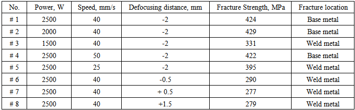
This article reports on an experimental investigation to weld high strength low alloy steel using YAG fiber laser at different processing conditions. Three level of the laser power were investigated: 2500 W, 2000 W and 1500 W, at fixed welding speed of 40 mm/s. Welding speeds of 50 mm/s, 40 mm/s and 25 mm/s were used at a fixed power of 2500 W. Moreover, the defocusing distance was changed from -2 mm to +1.5 mm at a fixed power of 2500 W and speed of 40 mm/s. Full penetration joints without any macro defects were produced by laser power more than 2000 W. While at 1500 W, partial penetration defect was occurred. The microstructure of the weld zone show acicular ferrite and bainite at higher power and martensite and some ferrite at lower power. When the laser speed was decreased to 25 mm/s, the width of the weld and heat affected zone became wide. Lack of penetration and other defects (porosity) with wide weld zone were appeared at defocusing distance more than -1 mm. The welded joints that welded with higher laser powers and negative defocusing distance gave fracture strength values very close to that of the base metal.
Keywords: HSLA steel, Laser welding, Laser power, Laser speed
Cite this paper: Ali Algahtani, Essam R. I. Mahmoud, Effect of Fiber YAG Laser Parameters on the Microstructural and Mechanical Properties of High Strength Low Alloy Steel, International Journal of Materials Engineering , Vol. 5 No. 5, 2015, pp. 113-120. doi: 10.5923/j.ijme.20150505.02.
Article Outline
1. Introduction
- In recent past, the demand of environment-friendly vehicles that have better fuel economy and lower CO2 emissions compels automakers to apply advanced technology and new materials in vehicle manufacturing [1–3]. Moreover, the increasing length of bridges, shipbuilding, and oil & gas transmission pipelines associated with their construction and operating costs has lead to the development of a new steel grades with light weight and higher performance [4-6]. To achieve these objectives, high strength low alloy (HSLA) steels can be used in all these applications. HSLA steels are high potential materials for light structures where considerable strength is required [7-8]. The combination of strength, toughness, formability and better performance both in high and low temperature enables construction engineers to use HSLA steel alloys with thinner thickness in many industrial applications [9]. During manufacturing of all these components, welding and joining are unavoidable. Many welding techniques such as metal inert gas/active gas (MIG/MAG) welding, tungsten inert gas (TIG) welding or other arc welding methods have been used for many years [10-11].The studies showed that these traditional methods have disadvantages of higher heat input generated which leads to problems such as as lager fusion and heat-affected zones, coarse grains, bigger deformations and more defects such as cracks and porosity in addition to low productivity [12-14].It is therefore advantageous to develop welding process that minimize heat input and maintain the fine grain structure that provides the strength and toughness. Low heat input welding operations also have the extra benefit of decreasing welding induced distortion [15-16]. Correcting distortion may require mechanical and/or thermal methods such as flame straightening operations which, if not carefully controlled, could also lead to grain growth and degradation of the mechanical properties. As such, laser welding has been given great expectations to solve these problems, as it has high welding speed, deep penetration, narrow bead width and low distortion [17]. A new generation of fiber lasers has been developed for industrial applications and has multiple advantages, including high power with small beam divergence, flexible beam delivery, low maintenance costs, high efficiency, compact size and ease of interface with robots [15-18]. Nd:YAG laser welding is becoming increasingly important and its share in the total laser industry is expected to grow substantially [19]. One of the reasons is that the high power density, lower maintenance costs, small beam divergence and focal spot diameter could lead to welds with a higher penetration and smaller width for a given welding speed [19]. During the process of laser beam welding, many factors, such as laser power, welding speed, focus position, work piece distortion and surface condition, influence the absorption rate of laser energy, and then the weld quality may be changed. In order to ensure good weld quality, the process control should be conducted during laser beam welding [20]. In laser welding, where energy density and cooling rates are very high, if compared to traditional arc one, and no filler material is used, the optimal source and the relating process parameters must be selected very carefully in order to achieve the optimum trade-off useful for obtaining a sound joint [21-22]. In this direction, this study aims to perform butt joint welding on high-strength low alloy steel materials with Fiber YAG laser, and to optimize the main processing parameters; laser power, welding speed and defocusing distance. Then, the tensile strength and the microhardness of the welds have been tested. Finally, the macro/ microstructure of the welds has been analyzed.
2. Experimental Work
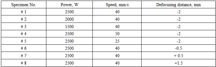
- The base material used in this study for welding was high strength low alloy steel sheets which were cut to size of 20 mm, 50 mm from 3 mm thick sheet. The chemical compositions and the mechanical properties of the base materials are provided in Tables 1 and 2, respectively. Prior to laser welding, the sample edges were ground to maintain positional accuracy and cleaned with fresh stainless wire brush followed by acetone swabbing, and then dried in the air. Welding was done as a butt joint perpendicular to the rolling direction of the sheets using a 3 kW YAG Fiber laser system. Welding was performed with a head angle of 00. Pure argon gas with a side nozzle at 15 L/min flow rate was used to protect the molten weld pool. To investigate the effect of the welding parameters on the macroscopic geometry, microstructure and mechanical properties of the joints, the welds were manufactured at various values of laser power, laser power, and defocusing distance. Three level of the laser power were investigated: 2500 W, 2000 W and 1500 W, at fixed welding speed of 40 mm/s and defocusing distance of -2 mm. Welding speeds of 50 mm/s, 40 mm/s and 25 mm/s were used at a fixed power of 2500 W and defocusing distance of -2 mm. Moreover, the defocusing distance was changed from -2 mm to +1.5 mm at a fixed power of 2500 W and welding speed of 40 mm/s. The welding conditions used for experimentation are summarized in Table 3.
|

|

|
3. Results and Discussions
3.1. Effect of Laser Welding Power
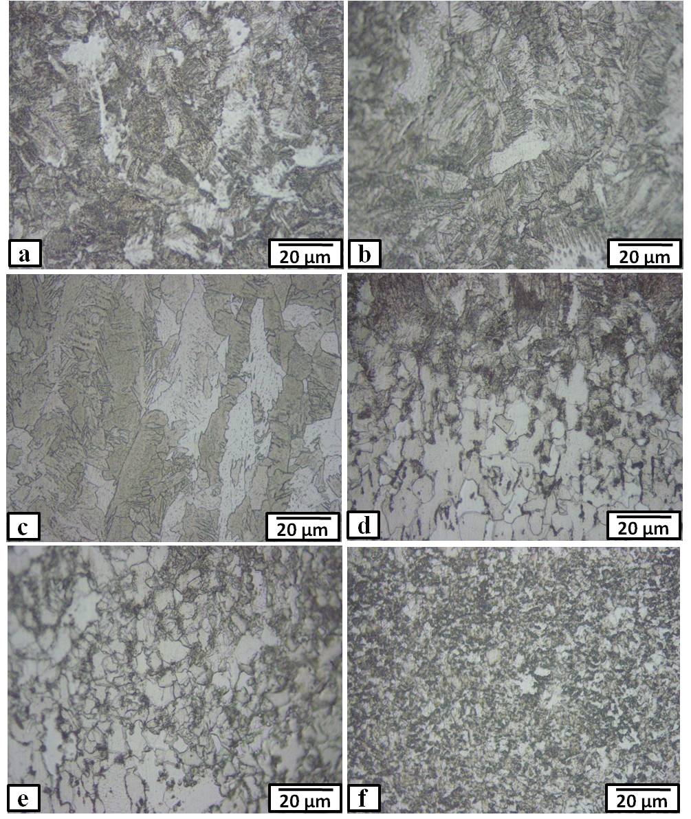
- The microstructures of the HSLA steel base metals used in this work are shown in Fig. 1. The structure was characterized mainly by fine-grained polygonal ferrite (light etching) interspersed with grains of pearlite (dark-etching) structure. The representative weld joint cross-sections macrographs of samples welded at different weld powers (2500 W, 2000 W, and 1500 W) at fixed welding speed of 40 mm/s and defocusing distance of -2 mm are shown in Fig. 2. As can be seen in all conditions, the laser weld joint had a typical “goblet” shape that had a relatively wide zone at the upper surface and narrow nether zone at the rest of the thickness. The width of weld joint was slightly decreased by decreasing the welding power. At power of 2500 W, the width was 0.59 mm, and that 2000 W was 0.45 mm. For the power of 1500 W, the width became 0.42 mm. These data were measured at almost the center of the weld thickness. At laser powers of 2500 W and 2000 W, full penetration joints were obtained without any macro- defects, such as pores and cracks. At lower laser power (1500 W); partial penetration was obtained (See Fig.2 (c)). The heat generated at this lower power was not enough to melt the full thickness of the sample. Microstructures of the weld and heat affected zone of the three joints are shown in Fig. 3. At laser power of 2500 W, as can be seen in Fig. 3 (a), the structure of the weld zone was consisting of acicular ferrite with interspersed bainite structure. This is due to the relatively slow cooling rate after melting by laser power of 2500 W. When the laser power was decreased to 2000 W (Fig. 3 (b)), the clear dendritic structure was appeared in the weld zone as a course columnar crystal that grew from the base metal interface towards the weld centreline (opposite to the direction of heat flow). This is due to the relatively fast cooling rate after lower heat input of 2000 W. The weld zone was consisted of predominately acicular ferrite with some bainite. At laser power of 1500 W, the structure of the weld zone was very fine due to the consequent high cooling rate (Fig. 3 (c)). The most probably structure of the weld zone after laser power of 1500 W was martensite and some ferrite as shown in a enlarged SEM micrograph in Fig. 4 (a). Regarding the heat affected zone as shown in Fig. 3 (d-f), the width of the HAZ remarkably decreased by decreasing the laser power. The HAZ is heated to a high temperature for a sufficient time and subjected to a complex thermal cycle (sudden heating followed by rapid cooling) over a wide temperature range. As a consequence, the HAZ consists of a variety of complex graded microstructures including all those phases existing in both the parent metal and the fusion zone. The transition of the microstructure from the weld zone to the base metal is illustrated in Fig. 3 (d-f). Their structures were consisted of ferrite, and partially decomposed pearlite observed at the grain boundary at welding power of 2500 W (see Fig. 3 (d). At lower power (1500 W), the HAZ structure was consisted of fine grains of acicular ferrite and bainite near the weld zone and the grains were gradually enlarged and changed to ferrite and partially decomposed pearlite by moving towards the base metal as shown in Figs. 3 (f) and 4 (b).
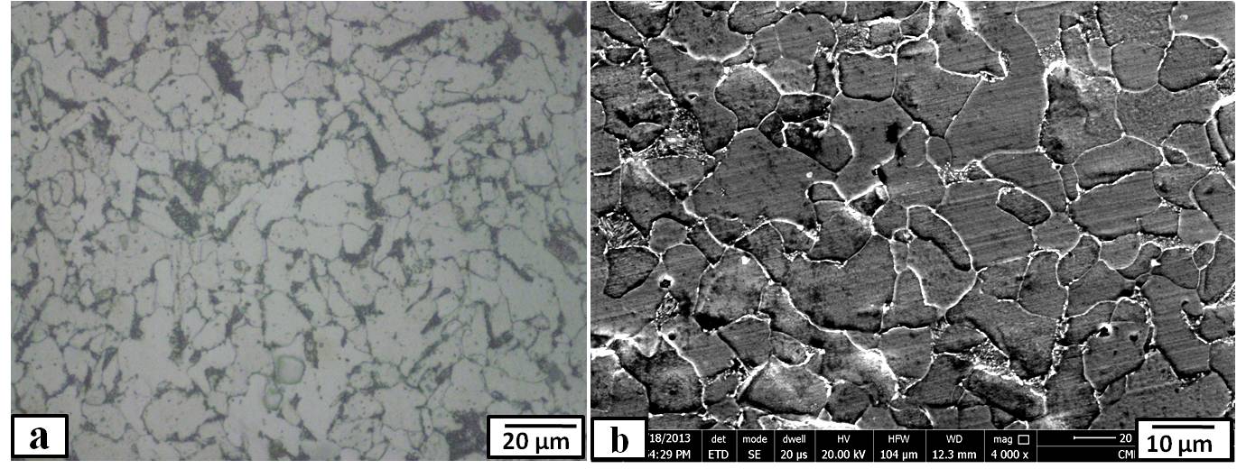 | Figure 1. Microstructure of the base metal |
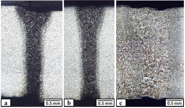
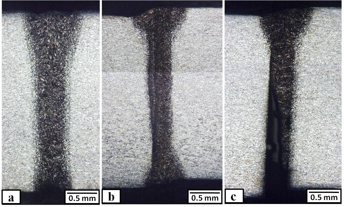 | Figure 2. Macrographs of the weld cross-sections at different laser power, where (a) 2500 W, (b) 2000 W, and (c) 1500 W |
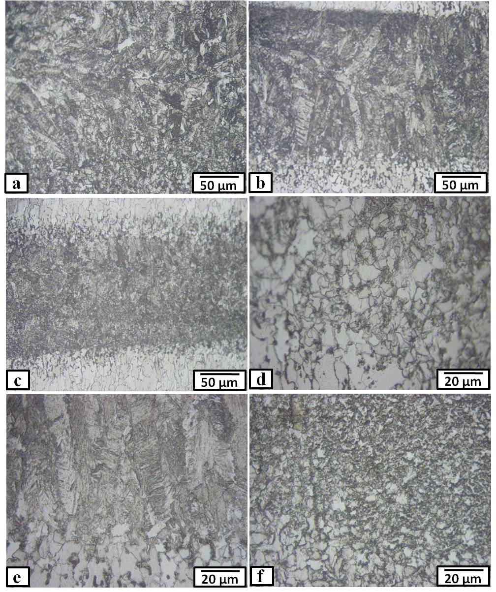 | Figure 3. Microstructure of the weld zone (a-c) and heat affected zone (d-f) at different laser power, where (a) & (d) 2500 W, (b) & (e) 2000 W, and (c) & (f) 1500 W |
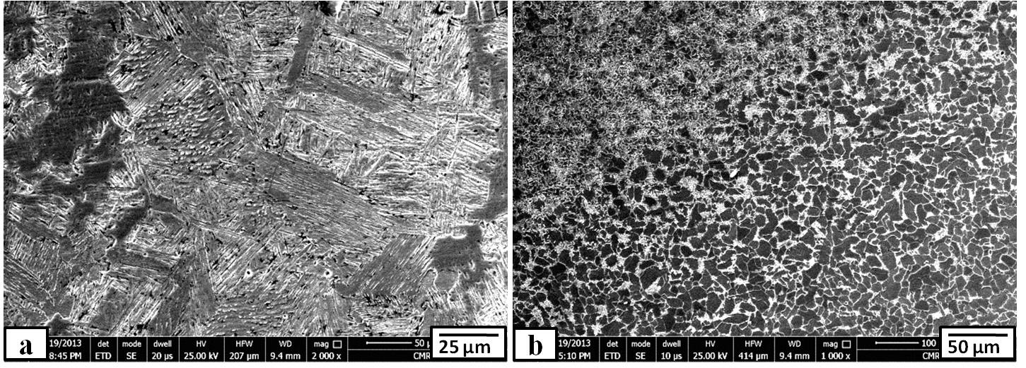 | Figure 4. SEM micrographs of the (a) weld zone and (b) heat affected zone welded with laser power of 1500 W |
|
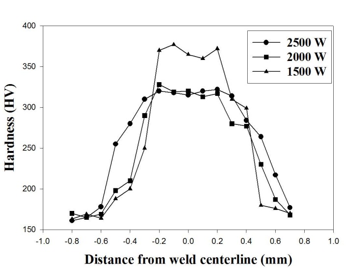 | Figure 5. Hardness distribution through the cross-section perpendicularly to the welding direction of the three joints welded with different laser powers |
3.2. Effect of Laser Welding Speed
- Optical macrographs of the different weld cross-sections welded at different weld speeds (50 mm/s, 40 mm/s, and 25 mm/s) at fixed welding power of 2500 W and defocusing distance of -2 mm are shown in Fig. 6. It is clear from these figures that full penetration joints were obtained at all conditions in this part. This is due to the higher laser power (2500 W) that used. It can be seen also that cracks and porosities cannot be found in all condition. However, the changes in the welding speed show a clear influence on the weld width and consequently on the microstructure formation within the weld zone and heat affected zone. The width of the weld zone (measured in the mid of the thickness) of sample welded with speed of 50 mm/s (0.42 mm) and 40 mm/s (0.59 mm) was closer with each other. For the weld zone welded with speed of 25 mm/s, the width was much larger than those of other conditions. It reached to 1.1 mm. The amount of energy that is delivered to the work piece plays major role in the weld size and the microstructure. The used low welding speed (high heat-input) causes to the fusion pool longer residence in high temperature zone and slower cooling rate. This leads to enlarge the size of the weld zone. Regarding the weld microstructure, at welding speed of 50 mm/s as shown in Fig. 7 (a), the structure was consisted of ferrite and bainite. When the welding speed was reduced to half (25 mm/s), the structure showed large grains of ferrite and bainite as shown in Fig. 7 (c). For the heat affected zone, its structure was very similar to that of the laser power. As the heat input increased (through decreasing the laser speed), the cooling rate is decreased. In consequently, the width of the HAZ is increased. Moreover, the microstructure of the HAZ changed from ferrite and partially decomposed pearlite (Fig. 7 (d)) at higher speed of 50 mm/s to equiaxed ferrite- pearlite structure (Fig. 7 (f)).
 | Figure 6. Macrographs of the weld cross-sections at different laser speed, where (a) 50 mm/s, (b) 40 mm/s, and (c) 25 mm/s |
 | Figure 7. Microstructure of the weld zone (a-c) and heat affected zone (d-f) at different laser speed, where (a) & (d) 50 mm/s, (b) & (e) 40 mm/s, and (c)& (f) 25 mm/s |
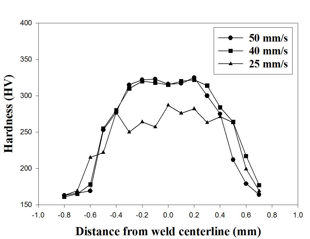 | Figure 8. Hardness distribution through the cross-section perpendicularly to the welding direction of the three joints welded with different laser speeds |
3.3. Effect of Defocusing Distance
- Firstly, it is important to define the defocusing distance of the laser beam. It is the relative position of the laser beam focus and the sample surface. A negative defocusing distance is defined as the sample surface is above the laser beam focus, while a positive defocusing distance is defined as the sample surface is under the laser beam focus. Fig. 9 shows the transverse welding cross-sections obtained at defocusing distance ranging from -2 mm to +1.5 mm at fixed laser power and speed of 2500W and 40 mm/s, respectively. It is clear from this figure that the width of the weld zone and HAZ increased with increasing defocusing distance. Moreover, the lack of penetration and other defects (porosity) were appeared at defocusing distance more than -1 mm, with the other process parameters held constant. This can be explained with concentration of the heat in each condition. At negative defocusing condition, the powder focus point and the powder concentration was below the molten pool; as a result, deeper materials will be melted. Similarly, when the defocusing distance is shifted to a more positive value, the laser focus point will be shifted to position above the molten pool. Based on this, more heat will be generated at the top surface, resulting in wide weld size in the top surface. This explanation was confirmed with the measured weld width as shown in Fig. 9. The weld width was 0.59 for defocusing distance of -2 mm. At defocusing distance of -0.5 mm, the width was 0.81 mm, and that + 0.5 mm was 0.89 mm. For the defocusing distance of +1.5 mm, the width became 0.99 mm. Moreover, there was inhomogenity in the microstructure of the weld and heat affected zones through the weld thickness at higher defocusing distance as shown in Fig. 10. Near the top surface, large grains were appeared due to lower cooling rate resulted from the more heat concentration in these areas. At the lower thickness portion, the weld zones were almost appeared as heat affected zone structure. The heat generated in these lower areas was not enough to melt of complete melt the faying edges of the two specimens.
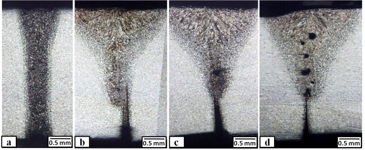 | Figure 9. Macrographs of the weld cross-sections at different defocusing distance, where (a) – 2 mm, (b) – 1 mm, (c) +0.5 mm and (d) +1.5 mm |
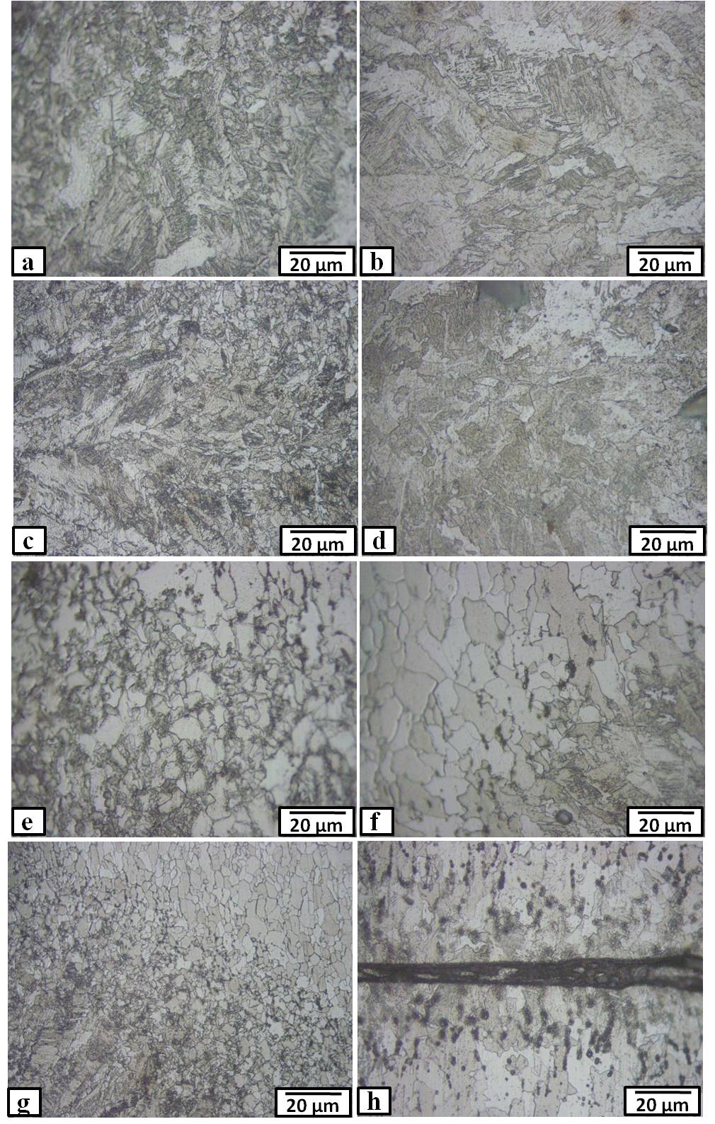 | Figure 10. Microstructure of the weld zone (a-d) and heat affected zone (e-h) at different defocusing distance, where (a) & (e) – 2 mm, (b)&(f) – 1 mm, (c)&(g) +0.5 mm and (d)&(h) +1.5 mm |
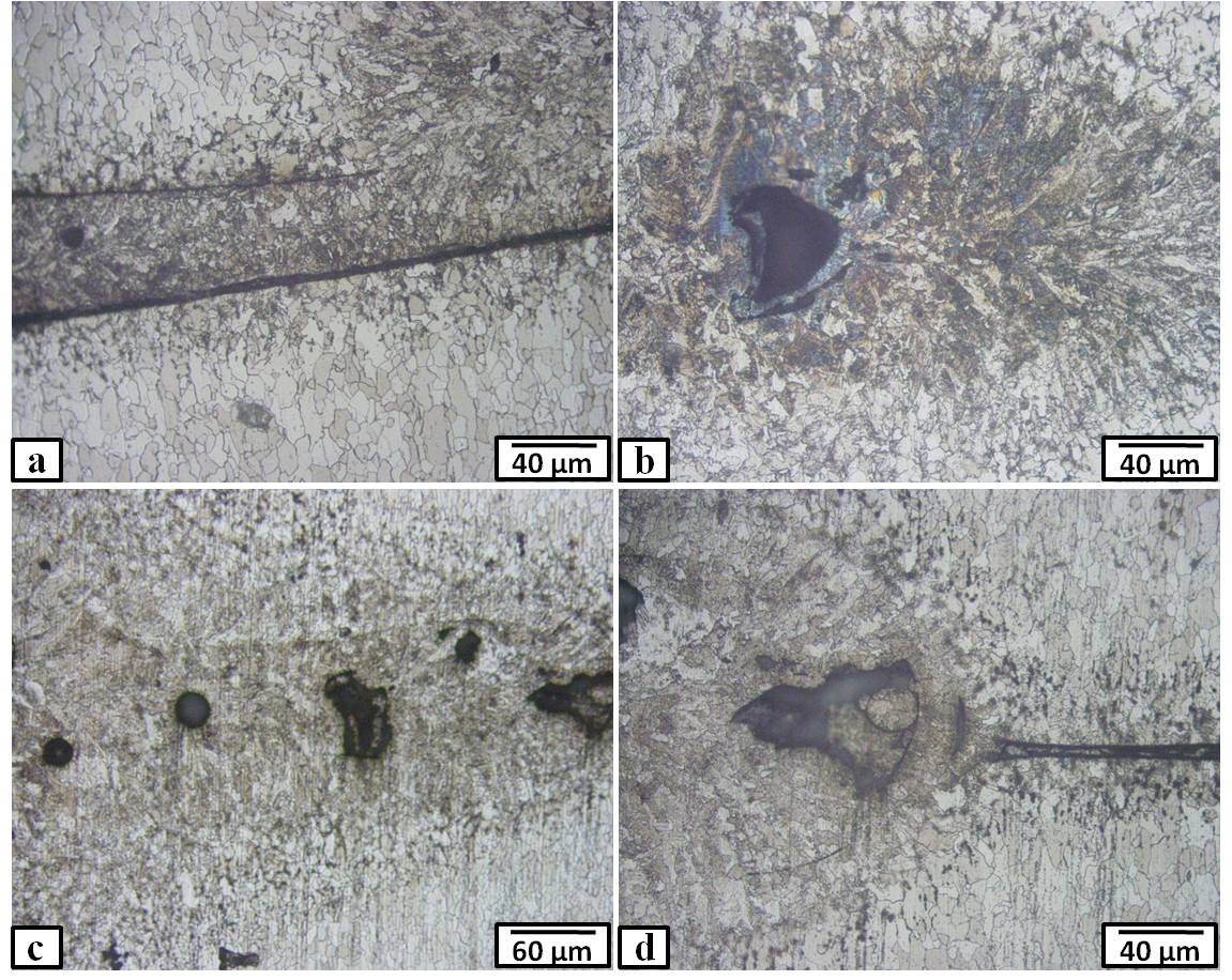 | Figure 11. Microstructure of some defected areas in the weld zone welded with different defocusing distance, where (a) – 1 mm, (b) +0.5 mm , and (c) & (d) +1.5 mm |
4. Conclusions
- In this work, high strength low alloy steel was welded using 3 kW YAG Fiber laser machine at different processing powers (2500, 2000, and 1500 W), laser speeds (50, 40 , and 25 mm/s), and defocusing distance (-2, -0.5, +0.5, and +1.5 mm). The macro/ microstructures of the weld and heat affected zones were investigated using optical and scanning electron microscopes. In addition, the fracture strength of the welded joints and hardness distribution through the cross-sections were evaluated. The results of this study led to the following conclusions:• Full penetration joints without any macro defects were produced by laser processing power more than 2000 W. While at laser processing of 1500 W, partial penetration defect was occurred. The width of weld and heat affected zones was narrow at all processing powers. This is at fixed speed and defocusing distance of 40 mm/s and -2 mm, respectively. • The laser speed has a remarkable effect on the width of weld and heat affected zones. As the welding speed decreases, their width is increased. The microstructure of the weld zone varies from acicular ferrite and bainite at lower speed to martensite and some ferrite at higher laser speed.• The joint penetration and the weld zone width depend on the laser beam defocusing distance. Lack of penetration and other defects (porosity) with wide weld zone were appeared at defocusing distance more than -1 mm, with the other process parameters held constant.• The fracture strength of the welded joints depends mainly of the welding power and defocusing distance. Close values to the base metal were achieved at higher laser powers and negative defocusing distance.