-
Paper Information
- Paper Submission
-
Journal Information
- About This Journal
- Editorial Board
- Current Issue
- Archive
- Author Guidelines
- Contact Us
International Journal of Materials Engineering
p-ISSN: 2166-5389 e-ISSN: 2166-5400
2015; 5(1): 10-16
doi:10.5923/j.ijme.20150501.03
Growth and Corrosion Behaviour of Amorphous Micrometre Scale Calcium Phosphate Coatings on Magnesium Substrates
 Abstract
 Reference
 Full-Text PDF
 Full-text HTML
Derek Fawcett, Sridevi Brundavanam, Gérrard Eddy Jai Poinern
Murdoch Applied Nanotechnology Research Group, Department of Physics, Energy Studies and Nanotechnology, School of Engineering and Energy, Murdoch University, Murdoch, Western Australia, Australia
Correspondence to: Gérrard Eddy Jai Poinern, Murdoch Applied Nanotechnology Research Group, Department of Physics, Energy Studies and Nanotechnology, School of Engineering and Energy, Murdoch University, Murdoch, Western Australia, Australia.
| Email: |  |
Copyright © 2015 Scientific & Academic Publishing. All Rights Reserved.
Amorphous calcium phosphate (ACP) coatings were formed on magnesium substrates via a straightforward electrochemical technique in order to improve the corrosion resistance of the substrates. X-ray diffraction spectroscopy and microscopy techniques were used to investigate the size, morphology, composition and structure of the ACP coatings. Analysis of the ACP coatings revealed the presence of micrometre scale fissures and tubular structures. Despite the presence of these features, the coatings were still capable of significantly reducing the corrosion rate in both PBS and Ringer’s solutions. Ringer’s solution was found to be the most aggressive towards Mg substrates with a corrosion rate of 3.828 mm/yr. However, after electrochemical treatment, the corrosion rate of substrates coated with ACP was reduced to 0.557 mm/yr. The significant improvement in corrosion resistance is a first step in controlling the corrosion rate of biodegradable Mg substrates for potential use in hard tissue applications.
Keywords: Biodegradability, Electrochemical synthesis, Magnesium, Calcium phosphates
Cite this paper: Derek Fawcett, Sridevi Brundavanam, Gérrard Eddy Jai Poinern, Growth and Corrosion Behaviour of Amorphous Micrometre Scale Calcium Phosphate Coatings on Magnesium Substrates, International Journal of Materials Engineering , Vol. 5 No. 1, 2015, pp. 10-16. doi: 10.5923/j.ijme.20150501.03.
Article Outline
1. Introduction
- Magnesium (Mg) is a silvery coloured metal that is currently being investigated as a potential biologically degradable implant material for bone tissue engineering. Mg is a lightweight metal with a high strength to weight ratio that also has a number of advantageous properties such as good biocompatibility and biodegradable in the aqueous physiological environment of the body [1]. In terms of mechanical properties, Mg is similar in nature to bone in terms of density and elastic modulus. The density of Mg is around 1.74 g/cm3 at 20 ºC, while bone tissue ranges from 1.8 to 2.1 g/cm3. In terms of elastic modulus, bone tissue varies from 40 to 57 GPa and pure Mg around 45 GPa [2, 3]. Interestingly, it is the close similarity between the elastic modules that makes Mg a potential biocompatible material suitable for reducing stress shielding and preventing bone resorption. Stress shielding and the resulting bone resorption are significant problems that can be encountered with conventional metallic implant materials [4]. In addition, unlike Mg, which has been shown to be physiologically beneficial in the body [5, 6], traditional metallic implants can release toxic metallic ions such as chromium, cobalt and nickel. The release of these toxic ions during biological corrosion and mechanical wear often leads to an unfavourable immune response that significantly reduces the biocompatibility of the implant and often leads to secondary revision surgery [7, 8]. However, before Mg can be used in the manufacture of biodegradable orthopaedic implants two fundamental problems need to be addressed and both stem from the metal’s rapid corrosion in chloride rich aqueous body fluids [9]. The first involves the rapid formation of hydrogen gas, which overwhelms surrounding tissues and results in the formation of subcutaneous bubbles [10, 11]. The second problem results from the rapid loss of mechanical strength and structural support between the Mg implant and the surrounding bone tissue that impedes the healing process. Therefore, effectively reducing the corrosion rate would significantly improve the mechanical and structural integrity of the implant for longer periods of time and also reduce the levels of subcutaneous gas formation. One interesting method of improving the corrosion resistance of a susceptible implant material is to coat it with a non-corrosive protective layer that is both biocompatible and bioactive. Bioactive coatings based on calcium phosphates have been successfully applied to coat variety of conventional metal implants in order to improve their biocompatibility and reduce the release of corrosion products into the human body [12].In this study an amorphous calcium phosphate (ACP) [Ca9 (PO4)6] coatings were formed on magnesium substrates during a straightforward electrochemical synthesis process. The electrochemical cell consisted of two electrodes. The first electrode was a platinum wire mesh (anode) and the second was an Mg substrate that acted as the cathode. Both electrodes were immersed in an electrolyte consisting of calcium nitrate and potassium di-hydrogen phosphate. ACP has a non-crystalline character that lacks long-range periodic uniformity normally associated with crystalline structures and readily precipitates from highly saturated aqueous solutions containing calcium and phosphate ions due to its lower surface energy [13, 14]. It has a spherical structural unit composed of randomly assembled clusters of ions approximately 9.5Å in diameter and also contained within the interstices is tightly bound water, which can be as much as 20% by weight of the particle [15]. It is the metastable properties of ACP in body fluids that makes it more osteoconductive than hydroxyapatite and also gives it superior biodegradability when compared to tri-calcium phosphate [16-18]. And because of its metastable properties, ACP will transform to a more thermodynamically stable crystalline calcium phosphate phase such as hydroxyapatite via a process of dissolution, nucleation, and crystal growth [19]. Advanced characterisation techniques such as X-ray diffraction (XRD) spectroscopy, Transmission electron microscopy (TEM), Scanning electron microscopy (SEM) and Energy Dispersive Spectroscopy (EDS) were used to determine size, morphology, crystalline structure and composition of the ACP coatings formed by the electrochemical process. The corrosion resistance of the coatings was then evaluated in phosphate buffer saline (PBS) solution and Ringer’s solution at body temperature (37ºC).
2. Materials and Methods
2.1. Materials
- All aqueous solutions were made using Milli-Q® water (18.3 MΩ cm-1) produced by an ultrapure water system (Barnstead Ultrapure Water System D11931; Thermo Scientific, Dubuque, IA). All chemicals and reagents used in this study were supplied by Chem-Supply (Australia).
2.2. Surface Pre-treatment of Mg Substrates
- High purity (99.9%) Mg foil 0.15 mm in thickness was cut into rectangular strips 40 mm in length and 3 mm in width. Silicon carbide (Si C) paper (1200 grit) was used to remove all surface oxides and contaminants. After initial surface cleaning, the strips were chemically cleaned in 5% wt. nitric acid (HNO3) solution followed by ultrasonically rinsing in acetone for 10 min. This was followed by rinsing with Milli-Q® water to remove acetone and then allowing the substrates to air dry. After drying the weight of each substrate was recorded using an Ohaus PA214C microbalance.
2.3. Electrochemical Synthesis of ACP Coatings
- The electrochemical cell was composed of two electrodes and an electrolyte. The electrolyte consisted of an aqueous solution containing 0.32 M of Ca (NO3)2.4H2O and 0.19 M of KH2PO4. The electrodes consisted of a platinum wire mesh (anode) and an Mg substrate, which was used as the cathode. A standard laboratory DC power supply [GW INSTEK GPS-2303] was used to supply the required voltage range with a maximum current density of 60mA/cm2 in the dynamic mode setting with a fixed voltage (6 V) and variable immersion times ranging from 30 s to 5 min.
2.4. Advanced Characterisation of Coatings
2.4.1. X-ray Diffraction (XRD) Spectroscopy
- XRD spectroscopy was used to identify the presence of any crystalline phases present in the surface coating formed during electrochemical synthesis. Spectroscopy data was recorded at room temperature, using a GBC® eMMA X-ray Powder Diffractometer [Cu Kα = 1.5406 Å radiation source] operating at 35 kV and 28 mA. The diffraction patterns were collected over a 2θ range of 20° to 60° with an incremental step size of 0.02° using flat plane geometry with 2 second acquisition time for each scan.
2.4.2. Transmission Electron Microscopy (TEM)
- The size and morphology of ACP particles formed during the synthesis process were investigated using TEM. Sample material taken from substrates was placed into small tubes containing Milli-Q® water, sealed and placed into an ultrasonic bath for 10 minutes. Suspensions were then filtered 2 times before a single drop from each sample was placed onto a carbon-coated copper TEM grid using a micropipette. After a 24-hour period drying period, samples were investigated using a Phillips CM-100 electron microscope (Phillips Corporation Eindhoven, The Netherlands) operating at 80kV.
2.4.3. Scanning Electron Microscopy (SEM) and Energy Dispersive Spectroscopy (EDS)
- The size and morphology of coating features formed on Mg substrates were examined using SEM, while the elemental composition of the coatings was investigated using EDS. All micrographs were taken using a JCM-6000, NeoScopeTM with attached energy dispersive X-ray spectroscopy. Samples were mounted on individual substrate holders using carbon adhesive tape before being sputter coated with a 2 nm layer of gold to prevent charge build up using a Cressington 208HR High Resolution Sputter coater.
2.5. Corrosion Resistance of ACP Coating
- The corrosion resistance of pure Mg substrates and ACP coating substrates was investigated using freshly prepared phosphate buffer saline (PBS) solution and Ringer’s solution. The composition of the PBS solution (in g/L) consisted of 8.006 NaCl, 0.201 KCl, 1.420 Na2HPO4 and 0.240 KH2PO4. The Ringer’s solution composition (in g/L) consisted of 8.6 NaCl, 0.6 KCl and 0.66 CaCl2.2H2O. The pH and temperature of both test solutions was maintained at 7.4 and 37ºC respectively so that body fluid pH and temperature could be replicated. An EG&G Princeton Potentiostat/galvanostat (Model 273A supplied EG&G Princeton applied research) using a three-electrode arrangement was used to generate polarization curves. The working electrode was a test substrate with a surface area of 1 cm2. The remaining two electrodes consisted of a saturated calomel electrode (SCE) that was used as the reference electrode, while the counter electrode was a platinum wire (Pt.). A Tafel test procedure was performed using a voltage range between -2.5 V and 1.0 V, with a step size of 10 mV and a 1s time interval for the 10 mV scan rate. From the resulting experimental polarization curves the corrosion rate (mm/yr.) was calculated.
3. Results and Discussions
3.1. XRD Spectroscopy and TEM Analysis
- The XRD technique was used to examine Mg substrates before and after the electrochemical process. Figure 1 presents a representative set of XRD patterns for untreated and treated substrates. Examination of the pattern for the untreated substrate reveals the presence of six peaks over the 2θ range from 20º to 60º. The pattern contains three major peaks [(002), (101) and (102)] and two minor peaks [(100) and (110)] that correlate to the crystalline structure of the Mg substrate. Also present in the pattern was a minor peak (101) that indicated the presence of Mg(OH)2 on the substrate surface. No other surface contaminants were found on the substrate. Subsequent electrochemical processing of substrates produced a thin white calcium phosphate coating over the surface. The coating was identified as amorphous calcium phosphate due to the presence of a very large broad and diffuse peak centred on the 2θ angle of 25°, characteristic of non-crystalline calcium phosphate materials [20]. However, three peaks could be seen in the XRD pattern [(002), (101) and (102)] and were identified as the underlining Mg substrate.The inserted TEM image presented in Figure 1 is a representative of the spherical morphology and highly agglomerated nature of the ACP particles that make up the surface coatings of the treated substrates. Particle size analysis revealed that the particles ranged in size from 60 nm up to 250 nm, with a mean particle size of 120 nm.
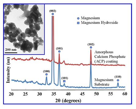 | Figure 1. XRD analysis of a representative Mg substrate and ACP coated substrate, with insert TEM image of synthesized ACP particles |
3.2. SEM and EDS Analysis of Coating Growth
- The SEM technique was used to study the growth of the ACP coating thickness during the electrochemical process. The technique was also used to investigate the surface features and structure of the coatings. Figures 2 (b), (c) and (d) present micrographs showing the growth and increasing coating thickness with treatment time. Figure 2 (a) graphically presents the growth in coating thickness and reveals that the growth rate varies during the treatment. At the end of the 5 minute treatment period, a typical coating reached on average a thickness of around 70 µm. Analysis of SEM micrographs of the coatings reveals there granular structure which can be seen throughout the cross-sections. In addition, with treatment time the coating tends to detach from the underlining substrate. Also noticeable were the very rough surfaces of the respective coatings that are exposed to the electrolyte and the presence of tubular surface features.
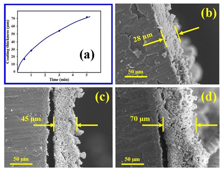 | Figure 2. (a) Growth of ACP coating layer; SEM micrographs of mean thickness measurements taken during growth of coating thickness with time at 6 V potential (b) 1 min; (c) 3 min, and (d) 70 min |
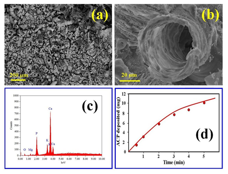 | Figure 3. (a) SEM micrograph of a typical coating surface landscape; (b) enlarged view of a surface tubular structure; (c) EDS elemental analysis, and (d) deposition rate of ACP coating with time |
3.3. Corrosion Resistance
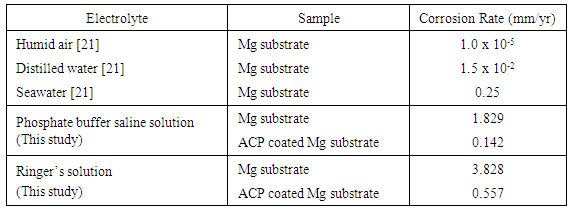
- The corrosion behaviour of pure Mg substrates and ACP coated Mg substrates were studied by immersing substrates into two types of aqueous mediums and then generate polarization curves using a three-electrode based a Potentiostat/galvanostat device. Both the PBS solution and the Ringers solution were maintained at 37 ºC and a pH of 7.4 during the test procedure. Representative polarization curves produced during the corrosion tests for pure Mg substrates and ACP coated substrates are presented in Figure 4. Inspection of the polarization curves of both PBS and Ringer solutions reveals that both solutions are highly corrosive to uncoated substrates. For example in seawater, the corrosion rate is typically around 0.25 mm/yr. [21], the PBS solution was calculated from the Potentiostat / galvanostat device to be 1.829 mm/yr. and Ringers solution was calculated to be 3.828 mm/yr. Clearly from these measurements it is clear that uncoated Mg substrates will rapidly corrode in these fluids without protection and explains why previous attempts of using Mg as an implant have failed to deliver satisfactory clinical outcomes. Ringer’s solution was found to be the most aggressive environment for Mg substrates and this was still the case for the ACP coated substrates. The ACP coating used in the corrosion studies was able to reduce the corrosion rate from 3.828 mm/yr. down to 0.557 mm/yr. A similar trend was also seen for the tests carried out in PBS solution. In this case the original corrosion rate of 1.829 mm/yr. was reduced to 0.142 mm/yr. as listed in Table 1.
|
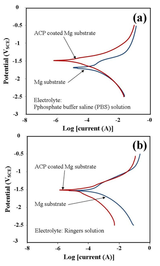 | Figure 4. Polarization curves generated during corrosion testing of ACP coated Mg substrates (70 µm coating thickness) in aqueous environments at 37 ºC and a pH of 7.4: (a) PBS solution and (b) Ringers solution |
4. Conclusions
- A straightforward electrochemical process was used to form ACP coatings on Mg substrates with the objective of improving the corrosion resistance of the substrate. XRD spectroscopy confirmed the formation ACP on the substrates while TEM image analysis revealed the characteristic spherical morphology normally associated with ACP particles. The image analysis also confirmed the highly agglomerative nature of the particles. SEM micrographs taken during the synthesis process reveal the formation and subsequent growth of micrometre scale tubular structures and surface fissures in the respective coatings. Despite the presence of both features, the coatings were still capable of significantly reducing the corrosion rate in both PBS and Ringer’s solutions. Ringer’s solution was found to be the most aggressive with a substrate corrosion rate of 3.828 mm/yr. However, the substrate corrosion rate was significantly reduced (0.557 mm/yr.) by the presence of a 70 µm ACP coating. The significant improvement in corrosion resistance of ACP coated substrates is an important result and the present study demonstrates the viability of using this electrochemical process to control the corrosion rate. Importantly, this improvement was achieved in spite of numerous tubular structures and surface fissures being produced during coating formation. The disadvantage of the ACP coating technique is unquestionably the presence of surface fissures and tubular structures. Conversely, the coatings advantages include biocompatibility, osteoconductivity, resorption potential and corrosion resistance. However, further studies are needed to build on these advantages and perhaps modifying the current electrochemical process to reduce the coating imperfections. Thus, being able to control the corrosion rate of ACP coated Mg substrates is an important first step in developing a programmable biodegradable Mg based implant for hard tissue applications.
ACKNOWLEDGEMENTS
- The authors would like to thank Mr Ken Seymour for his assistance with the XRD measurements and Associate Professor Gamini Senanayake for his assistance with the electrochemical measurements. Mrs Sridevi Brundavanam would like to acknowledge Murdoch University for providing a PhD Scholarship to undertake her PhD studies.