-
Paper Information
- Previous Paper
- Paper Submission
-
Journal Information
- About This Journal
- Editorial Board
- Current Issue
- Archive
- Author Guidelines
- Contact Us
International Journal of Materials Engineering
p-ISSN: 2166-5389 e-ISSN: 2166-5400
2014; 4(6): 196-202
doi:10.5923/j.ijme.20140406.03
Improvements in Bonding of Silicon Carbide Ceramic to Metals
 Abstract
 Reference
 Full-Text PDF
 Full-text HTML
D. Starikov1, R. Pillai1, T. Glenn2, J. Gandhi1, 3, A. Price1, R. Delaney1, A. Bensaoula1
1Integrated Micro Sensors Inc, Houston,
2Ultimate Composites Analysis, Piedmont
3Department of Physics, University of Houston, Houston
Correspondence to: D. Starikov, Integrated Micro Sensors Inc, Houston,.
| Email: |  |
Copyright © 2014 Scientific & Academic Publishing. All Rights Reserved.
Bonding of silicon carbide (SiC) based ceramic to other materials, such as metals, is of high importance for many advanced applications in fusion reactors, hot gas path turbine and rocket components, and chemical reactors. In this work, we demonstrate that the improvement of bond strength between SiC ceramic and metals is feasible by the employment of micro-column arrays (MCA). MCA were fabricated by pulsed laser ablation on the surfaces of the materials prior to bonding. Computer based simulation and experimental analysis for select materials explain the advantages of employing the MCA technology. The experimental results show that employment of MCA structured surfaces result in significant improvement of bond strength, with over 300% increase in bond strength forbond-in-tension (BiT) configuration, and over 100% increase in bond strength for the lap shear configuration. In addition, cracking of the SiC ceramic during bonding is attributed solely to the CTE mismatch between brazing alloys and SiC, and will be addressed in future work.
Keywords: Aerospace materials, Ceramics, Silicon Carbide, Bonding, Micro-column array, Laser surface modification
Cite this paper: D. Starikov, R. Pillai, T. Glenn, J. Gandhi, A. Price, R. Delaney, A. Bensaoula, Improvements in Bonding of Silicon Carbide Ceramic to Metals, International Journal of Materials Engineering , Vol. 4 No. 6, 2014, pp. 196-202. doi: 10.5923/j.ijme.20140406.03.
Article Outline
1. Introduction
- Silicon carbide (SiC) based ceramics are very important for advanced ultra-high temperature and extremely harsh environment applications in fusion [1-3], hot gas path components for turbines and aerospace systems [4, 5], as well as armor and semiconductor applications [6]. Due to extreme hardness and relatively low ductility, SiC ceramic parts cannot be machined and assembled into reliable structural components. Therefore, bonding of SiC ceramic parts to various metals is used to simplify their integration in various systems and structures. While the SiC ceramic/metal bonds are not necessarily exposed to ultra-high temperatures, strong acids, or bases, they are still subjected to considerable environmental impacts and mechanical and thermal loads and stresses. Brazing and adhesive bonding are the most common methods for joining of SiC based ceramic with metals. However, due to high chemical and thermal inertness of SiC and high differences in coefficients of thermal expansion (CTE) between SiC based ceramics and metals, the bonds are either not formed, or have a very low reliability.Efforts by several groups have been focused on the improvement of brazing of SiC based ceramic to various materials, including low thermal expansion glass [7], and metal alloys [8], however, employment of intermediate complex matrix nanocomposites of SiC with/and different fillers [9-11], is lately being intensively investigated for improvement of SiC ceramic bonding to various metals. We have previously reported substantial improvements in bonding of similar (Ti/Ti and CFRP/CFRP) and dissimilar (Si3N4based ceramic/Ti alloy and CFRP/metal) materials by employment of micro column arrays (MCA) formed by pulsed laser ablation on the surfaces of the materials prior to bonding [12-14]. Here, we present our results on the improvement of the bond strength between SiC ceramic and selected metals by applying of the MCA structures to surfaces of both materials prior to bonding. In the following section we present detailed description of stages that involved optimization and testing of the bond strength. These include (1) formation and optimization of the MCA fabrication on SiC ceramic and select metals, (2) modeling of the SiC ceramic/metal bonds, fabrication and bonding of MCA structured and unstructured SiC ceramic and metal coupons, (3) brazing and adhesive bonding of the SiC ceramic coupons to the metal coupons, and (4) testing of the bond strength of the coupon structures assembled in various configurations.
2. Experimental Work, Modeling, and Testing
- The SiC based ceramic selected for our experiments was Hexoloy® SA silicon carbide produced by pressure less sintering of submicron silicon carbide powder. This material can be formed into complex shapes with greater than 98% theoretical density, and reliably performs at temperatures in excess of 1900˚C in open air. Hexoloy® SA SiC is highly resistant to corrosion, erosion, sliding wear, high temperature, and thermal shock [15].The first metal selected for bonding to SiC based ceramic was Ti6Al4V titanium alloy, which exhibits high strength, low weight/volumeratio, outstanding corrosion resistance, good machinability, and excellent mechanical properties [16].The second metal selected for bonding with SiC ceramic was Kovar, an iron-nickel-cobalt alloy with a controlled coefficient of thermal expansion similar to that of hard glass and alumina ceramic. This makes it suitable for uses, which require a matched-expansion seal between metal and glass or ceramic parts [17].For brazing, we used Incusil ABA, a high-purity active braze alloy of silver, copper, indium, and titanium (59.0% Ag, 27.25% Cu, 12.50% In and 1.25% Ti), developed for direct application to ceramic surfaces. This brazing alloy wets and bonds to virtually any metallic surface, as well as to non-metallics, such as oxides, nitrides and carbides. It allows ceramic-to-ceramic and ceramic-to-metalsurfaces to be brazed without metallizing, firing, or electroplating, while cutting manufacturing time and costs of ceramic/metal assemblies, and produces strong, highly reliable and vacuumtightbrazed joints [18].
2.1. Formation and Optimization of MCA Structures
- A 100 W, ND: YAG marking laser with a wavelength at 1.06 µm was used for MCA processing of all samples in this study. The laser pulse parameters that were varied during the MCA optimization process were: laser current (A) proportional to the average laser power, pulsing frequency (kHz), and laser pulse duration (µs). The laser is equipped with galvoheads that allow for computer programmable laser beam scanning in two orthogonal directions with a predefined speed. All SiC ceramic samples were processed in argon atmosphere conditions provided by using a small chamber equipped with valves for argon purging. We applied 36 sets of pulsed laser ablation parameters for SiC ceramic MCA processing. Only three of them resulted in applicable MCAs and only one has been selected for processing of all SiC ceramic coupons used in this work. This selection was based on absence of micro cracks observed on SEM images taken from samples processed by using the other two recipes. This selected recipe is based on setting the following laser system parameters: 15.5 A laser current, 176 mm focal length, 4 mm/s scan speed, 1.6 μs pulse width, 25 μm hatch gap, and 5 kHz frequency The SEM images of the corresponding processed sample surface are shown in Figure 1a. Figure 1b represents SEM images of the MCA processed Ti alloy coupons and Figure 1c shows optical images of the laser processed Kovar coupons.The processing of the Ti alloy was optimized in a similar manner. Over 37 recipes were tested by varying power, pulse width, scan speed, and hatch spacing. Unlike SiC, the Ti alloy samples were processed in ambient air, which proved effective, more convenient, and cost effective. Two optimized recipes resulted in the most regular MCA structures with drastically increased specific surface area. The first recipe had the following set of parameters: laser current of 16.3 A, focal distance of 177.5 mm, 25 μm hatch gap, 1μs pulse width, 4 mm/s scan speed, and 5 kHz frequency. Figure 1b shows SEM images of the Ti alloy sample processed by using this recipe. The second recipe had a slightly higher current of 16.4 A. This recipe was selected based on the better ordering of the MCA structure and the health of the individual columns.
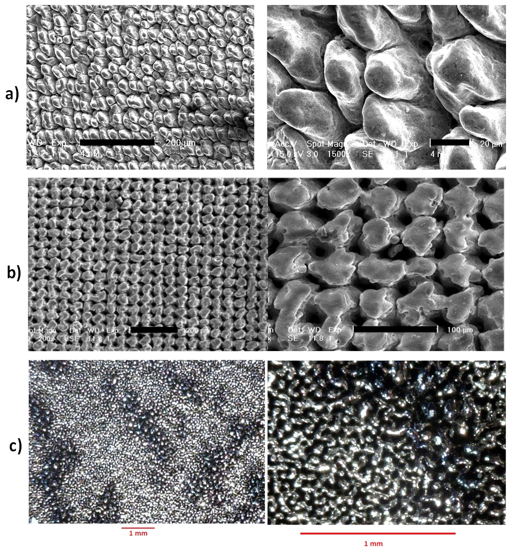 | Figure 1. MCA processed surfaces: a) SEM images of: (left) SiC samples processed under argon ambient, with a laser frequency of 5 kHz, 15.5 A current, scan speed of 4 mm/s, pw 1.6 μs, 176 mm focal length and 25 μm hatch spacing; (right) magnified image of MCA; b) SEM images of different magnification showing Ti alloy samples processed under ambient air, with a laser frequency of 5 kHz, 16.4 A current, scan speed of 4 mm/s, pw 1 μs, 177.5 mm focal length and 25 μm hatch spacing; c) Optical images at low (left) and high (right) magnifications of the MCA processed Kovar coupon surface |
2.2. Simulation of Materials/Structures Performance
- Prior to fabricating samples for testing, we performed modeling of the bond between metal and ceramic surfaces with and without the MCA structures in order to understand the potential failure mechanisms. We used ANSYS Structural finite element analysis application (Figure 2), that represents a best in class engineering analysis software, providing linear and nonlinear solution capabilities by incorporating, nonlinear temperature-dependent material properties into a nonlinear structural analysis. Rectangular shape coupons were defined and modeled using ANSYS Structural software. First, non-structured material assemblies were modeled. Figure 2a shows the structural model with constraints along the Uy and Uz direction, allowing the structure to move along the x direction. The bottom metal material is Kovar and the ceramic material is SiC. A theoretical load of 250 lb, which corresponds to a shear stress of 5000 lb/in2 at the bond interface, is applied along the x-direction on the Kovar side of the bonded coupons. Of the materials that we investigated, Kovar, and SiC ceramic have the closest CTEs. Incusil ABA was used due to its high bond strength and relatively low temperature of brazing. The model shown in Figure 2b includes an interface that is representative of a thin layer of Incusil. The stress under load is shown in Figures2c and 2d. A stress concentration in the middle of the SiC coupon of 93450 Psi is shown in Figure 2e Figure 2f shows the SiC ceramic/Incusil centerline bond stress along the z axis (peel stress). The resulting maximum stress is 47401 Psi. Similarly, a model was built to study the improvement of the SiC/Ti alloy bond by employing MCA structures on the bonded surfaces of the two material coupons. Figure 2g shows the micro columns with 30 μm base diameter and 30 μm height uniformly distributed with 200 μm spacing on the surface of the material bond area. Figure 2g also shows the maximum stress along the x direction of 126237 Psi. Figure 2h shows the SiCceramic/ Incusil centerline bond strength with a maximum stress of 57114 Psi along the z direction.
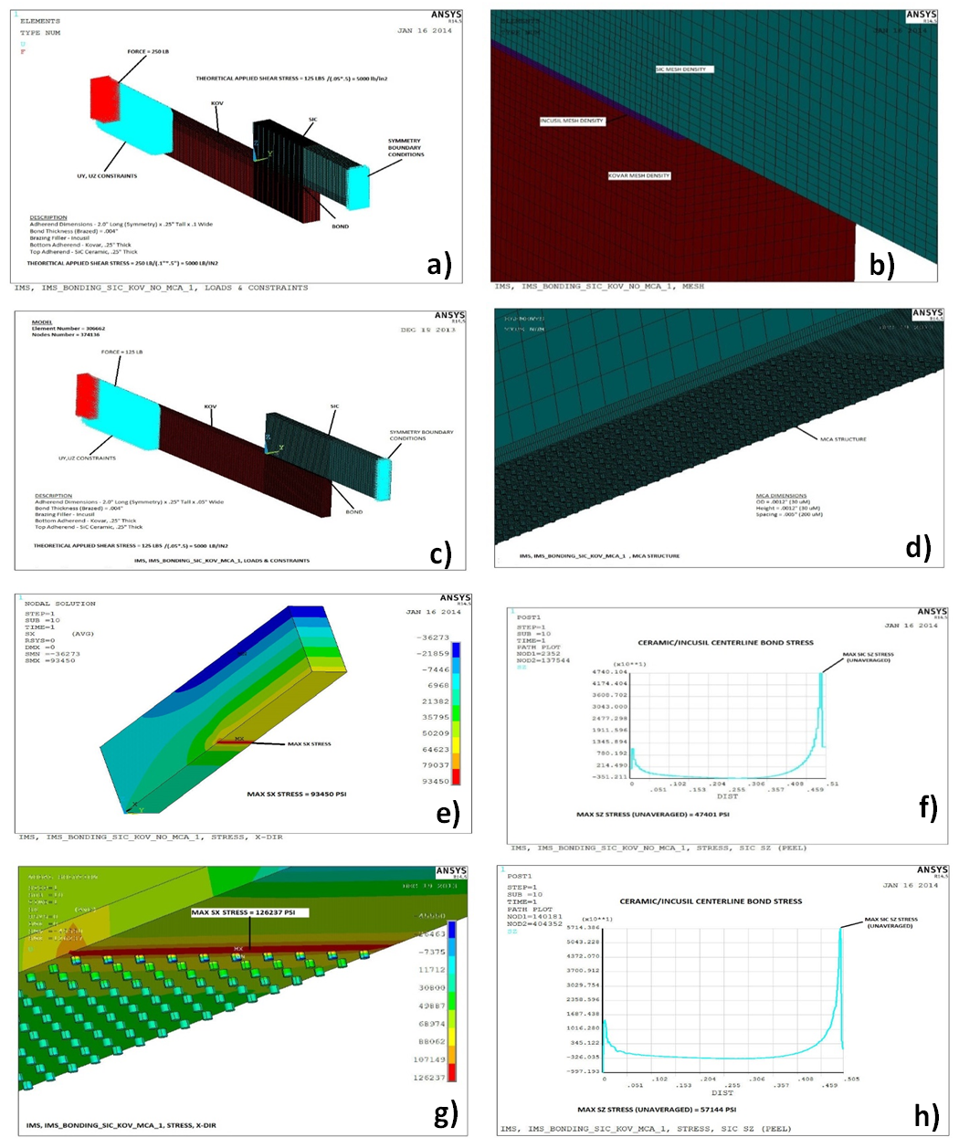 | Figure 2. ANSYS Structural finite element analysis: a) Model showing the applied stress and constraints between a Kovar and SiCceramic coupon;b) Model showing the Incusil at the interface between the two materials; c) Model built to study the bond improvement by employing of MCA processing; d)Micro columns with 30 μm base diameter and 30 μm height uniformly distributed with 200 μm spacing on the surface of the material bond area; e) Stress distribution under load along x axis. Stress concentration in the middle of the SiC coupon is 93450 Psi; f) Ceramic/Incusil centerline bond stress along the z axis. Maximum stress in SIC coupon is 47401 Psi; g) Maximum stress along the x direction of 126237 Psi; h)Ceramic/Incusil centerline bond stress along the z axis. Maximum stress in SIC coupon is 57144 Psi |
2.3. Bonding of SiC Ceramic to Kovar and Ti6Al4V Titanium Alloy
- The bonding of SiC ceramic and metal coupons was performed in two configurations: lap shear pulling tests, and bond-in-tension (BiT) or tensile pulling tests.Brazing was performed in a 4-zone high temperature quartz tube furnace with capabilities of reaching temperatures in excess of 1000℃. The quartz tube was purged with argon gas and the samples were loaded and held together in accommodating fixtures during the brazing process, which occurred in an argon atmosphere. The assemblies containing the fixtures and coupons were positioned in the center of the furnace for maximum temperature uniformity. The brazing material used for these experiments was an 85 μm thick Incusil ABA foil. The foil was placed in the bond area prior to loading into the holding fixtures. First, we bonded unprocessed (no-MCA) SiC ceramic coupons to unprocessed (no-MCA) Ti alloy and Kovarcoupons. Ti alloy and Kovar coupons were sandblasted prior to bonding with the SiC ceramic coupons. The brazing was performed by heating in two stages: first keeping them at 500℃ for 20 min, and then at 730-744.5℃ for 15 min, before gradually cooling down the furnace. Once the Ti alloy/SiC ceramic/Ti alloy coupons were taken out of the furnace, we noticed that SiC ceramic coupons were already cracked near the bond areas and had separated from the Ti alloy coupons even before further handling.In order to find out if the bonding will benefit from employment of the MCA structuring of the surface, we bonded two unprocessed (no-MCA) Ti coupons with a partially processed SiC coupon. This means one side of the SiC was processed and had MCA structures on it, while the other was unprocessed (with no MCAs on it). We followed similar brazing regimes as in the case of the previous samples. When the samples were pulled out of the furnace tube the only coupon that was intact with the Ti alloy coupon was one with the MCA processed surface. There was a hairline crack on the SiC ceramic coupon several millimeters away from the bonding interface, but it was still in one piece. On the other side of the assembly, with no MCAs, the SiC ceramic had cracked completely and detached from the Ti alloy coupon. Unfortunately, applying a small torque by hand on the side of the SiC ceramic coupon with MCAs was enough to break the SiC ceramic coupon along the crack line, while the several millimeter thick bonded part of the SIC ceramic coupon stayed firmly in place. In order to study the nature of the effect of the brazing alloy on SiC coupon, we placed a small piece of Incusil foil on a slab of SiC and followed normal brazing annealing procedures described above. After the brazing, we observed that the Incusil foil by itself was sufficient to create enough residual stress on the SiC coupon to initiate a crack. A portion of the SiC coupon came off with the Incusil foil when it was pulled apart by hand. Brazing of MCA processed SiC ceramic to MCA processed Kovar by using Incusil ABA was performed in a way similar to SiC ceramic/Ti alloy brazing. While brazed assemblies survived handling, cracking of the SiC coupons several millimeters from the bond interface occurred during loading into the stress test equipment. The fracture most likely resulted from very insignificant misalignment of the gripping fixtures in the load frame that created enough torque to break the thermally pre-stressed SiC ceramic coupons.Based on the technical data and specifications supplied by materials manufacturers, Kovar has a CTE that is closer in value to SiC ceramic than that of the Ti alloy employed in our previous tests. In addition, we have already shown above that MCA processing of SiC coupons, besides improvement of wettability, allows for the relaxation of the residual stress in an at least several millimeters thick SiC ceramic layer within the bonding interface. Thus, the cracks in SiC developed during brazing to the Ti alloy and Kovar coupons are primarily due to the difference in CTE between SiC ceramic and Incusil brazing alloy. The broken parts of the samples, each with a thin piece of SiC ceramic still bonded to the metal surface by the brazing material were preserved for testing in a shifting configuration, where the maximum force was applied in a direction parallel to the bonding interface and as close as possible to the bond line. Compared to pulling,this method allowed for minimal cracking of SiC coupons during shear stress testing.Several coupons were also fabricated for the BiT testing. The 0.0625” thick 0.75x0.75” square SiC ceramic coupons were MCA processed on both sides using the optimized recipe, and Kovar and Titanium alloys coupons were processed to form MCA structures on the surface designated for bonding. The Ti alloy/SiC ceramic/Ti alloy and Kovar/SiC ceramic/Kovar assemblies with MCA processed and unprocessed surfaces were then brazed in the tube furnace by using Incusil ABA as a brazing alloy.In order to study potential advantages that can be introduced by the MCA technology for adhesive bonding, we used a high strength high temperature (over 150°C) carbon nanotube reinforced Epovex® epoxy from Zyvex Technologies [19] to bond SiC ceramic/Kovar and SiC ceramic /Ti alloy assemblies. The epoxy has a high strength of 4,500 Psi, and is cured at a low temperature of 80 oC in a conventional laboratory oven. We bonded a non-processed (no MCA) SiC ceramic coupon to a non- processed (no MCA) Kovar coupon to be used as the reference sample for both Kovar and Ti alloy coupons bonded to SiC ceramic, assuming there is no chemical reactions between the adhesive and both metals. We also bonded MCA structured SiC ceramic and Kovar coupons and MCA structured SiC and Titanium alloy coupons. All samples were bonded in the same batch.
2.4. Testing the Bond Strength of the Assembled Coupon Structures
- By using the shifting technique we were able to test the bond strength of the broken SiC ceramic/Kovar coupons. On average the MCA processed surfaces had higher shear bond strength than the non-MCA ones. The stress testing results are illustrated in Figure 3. Bonding of Ti alloy to SiC ceramic indicated almost 100% increase in bond strength from 1000 Psi to over 2000 Psi as shown in Figure 3a. The results of shear stress testing (Figure 3b) of the adhesively bonded samples indicate 30% and 12% increase of the bond strength for Kovar/SiC ceramic and Ti alloy/SiC ceramic, respectively, by employment of MCA processing.
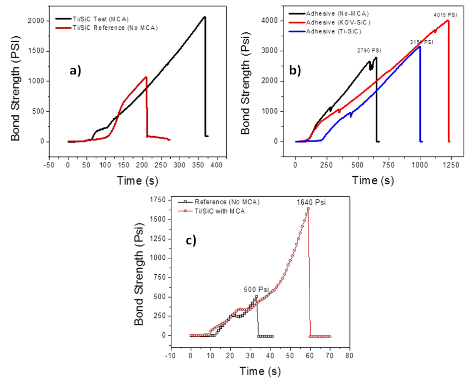 | Figure 3. Stress testing results: a) Bond strengths for brazed MCA processed and unprocessed Ti alloy/SiC ceramic samples; b) Improved adhesive shear bond strength of MCA structured coupons over unstructured coupons; c) Tensile bond strength of the adhesively bonded MCA structured and unstructured assemblies |
3. Conclusions
- The results on Ti alloy/SiC ceramic structures brazed by using Incusil brazing alloy show an increase of over 100% in bond strength from 1,000 Psi to over 2,000 Psi by using MCA technology on the pre-bonded surfaces. However, we believe the bond could be stronger, if the built in stress was better managed by applying a longer cool down process and a brazing alloy with a better matching CTE. A high strength high temperature epoxy was used for adhesive bonding to demonstrate bonding improvement provided by the MCA surface modification.In the shear test configuration, the MCA structured coupons showed a higher bond strength than the unstructured coupons, with over 30% increase in the bond strength of Kovar/SiC ceramic coupons and a 12% increase for the Ti alloy/SiC ceramic coupons. Moreover, the bond strengths are much higher for the epoxy bonded coupons (e.g. 4,000 Psi for Kovar/SiC ceramic) than for the brazed coupons (e.g. 2,000 Psi for Kovar/SiC ceramic). This highly suggests that existence of a residual stress is a determinant factor for the bond failure in the brazed coupons. We observed that the brazed structures indicated as high as 100% improvement in bond strength, proving that MCA structuring reduces the built in stress, due to the inherent elasticity of the micro columns. Bond-in-tension (tensile) test using adhesive bonding shows over 300% improvement in bond strength for MCA structured coupons. It was evident that MCA structuring improved adhesion of the epoxy with the coupon surfaces, while the epoxy easily delaminated from non-structured surfaces.
ACKNOWLEDGEMENTS
- We would like to acknowledge funds from the DOE SBIR Phase I award to Integrated Micro Sensors Inc, and Department of Civil Engineering of the University of Houston for providing the testing facilities and guidance. We would like to thank Prof. Mina Dawood and Dr. El-Tahan, Mossab for their assistance and guidance in setting up the experiments.