Bello Sefiu Adekunle1, Adewuyi Benjami Omotayo2, Adeyemo Raphael Gboyega1, Olaniyan Tirimisiyu Abiola1, Momoh Itopa Monday2, Shogbamu Emmanuel Adebayo2
1Department of Metallurgical and Materials Engineering, University of Lagos, Akoka, Yaba Lagos Nigeria
2Department of Metallurgical and Materials Engineering, Federal University of Technology, Akure, Ondo State Nigeria
Correspondence to: Bello Sefiu Adekunle, Department of Metallurgical and Materials Engineering, University of Lagos, Akoka, Yaba Lagos Nigeria.
| Email: |  |
Copyright © 2014 Scientific & Academic Publishing. All Rights Reserved.
Abstract
A rapid cooling casting machine was designed, fabricated and tested. The possibility of the amorphous aluminium ball production through water and brine atomisation was investigated. The ball was produced from the off cut aluminium waste at different falling speeds and cooling rates. The morphology and hardness values of the produced balls were examined. The scanning electron micrographs revealed that the network of second phase particles increased with increased falling speeds and higher cooling rate. The hardness value determination showed that there was 68.42% increase in hardness values of the water atomisation amorphous aluminium ball and 70% in hardness values of the 0.1 molar brine atomisation amorphous aluminium balls as the falling speed increased from 40 to 67ms-1. In addition, diameter of the amorphous aluminium balls increased as the falling speed increased and the cooling rate decreased. The produced amorphous aluminium balls can be used as grinding media for soft material such as discarded polymeric materials for recycling processes.
Keywords:
Design, Amorphous aluminium balls, Casting speed, Cooling rate, Microstructure
Cite this paper: Bello Sefiu Adekunle, Adewuyi Benjami Omotayo, Adeyemo Raphael Gboyega, Olaniyan Tirimisiyu Abiola, Momoh Itopa Monday, Shogbamu Emmanuel Adebayo, Design, Fabrication and Testing of Rapid Cooling Casting Machine: Production of Amorphous Alloy Balls, International Journal of Materials Engineering , Vol. 4 No. 4, 2014, pp. 123-128. doi: 10.5923/j.ijme.20140404.01.
1. Introduction
A rapid solidification is a process employed for the production of amorphous/glassy metallic alloy. It involves cooling of molten metal at a rate as high as 106 to 108℃ per second whereby the molten metal will not have sufficient time to crystallize [1]. In order to obtain a rapid solidification, a relatively thin molten layer must be brought into good thermal contact with a powerful heat sink [2]. Apart from single splat process and continuous process, atomization is one of the important manufacturing techniques where rapid solidification is employed [3]. Atomization is the breaking up of liquid into droplets which cool rapidly into particles. The atomization is the preferred method for producing rapidly solidified metal and alloy balls/powders. These balls/powders may not be obtained easily by conventional processing routes. The benefits of this process are the high cooling rate, reduced segregation, increased solid solubility, elimination of segregation phases, finer microstructure, consolidated products and high production rates [4]. Different manufacturing processes such as continuous casting have been used in the production of metal/alloy balls which are either used as rollers in ball bearing, grinding media in planetary mills or fine metallic particles in sand blasting. Particle breakage is an inevitable branch in mineral beneficiation and in other sectors [5]. The essence is to reduce the mineral particle size to the much smaller ones for further processing. The types of alloy used in the ball production depends on its application such as tungsten carbides and steels balls used as grinding media and rolling balls in crushing/planetary mill and ball bearing [6].Manufacturing a new product to answer a specific environmental need begins with design which is a production guide. Design is the creation of a product which satisfies a certain need. A good design should result in a product that performs its function efficiently and economically within the imposed constraints. Cost, reliability, safety, level of performance, pollution and energy consumption are among the major constraints [7]. It is done on three different levels which are: development of existing products or designs through introducing minor modification in size, shape or materials to overcome difficulties in production or performance; adaptation of existing products to work in new environment or to perform different functions and creation of a total new design that has no precedent [8, 9]. An experimental set up for centrifugal casting of ceramic slurry using the motor of a laboratory centrifuge, a suitable rotor head capable of holding tightly the casting mould while rotating in the motor axis and alumina tube were designed and fabricated [10]. A centrifugal casting machine was successfully designed and fabricated. The operation of the machine was based on the principle of centrifugal force. The machine was tested through the casting of aluminium alloy. The result revealed that it was able to cast a 60kg aluminium alloy successfully [11]. The jominy end quench machine was designed, manufactured and tested. The manganese steel was developed and water quenched, the hardenability values of the manganese steels were examined with the machine. Results revealed that the Jominy end quenched machine worked effectively with short cycle time and improved water management system [12]. In this present work, amorphous aluminium balls were produced with the aids of atomization process. In order to produce the amorphous balls, a rapid cooling machine was designed, fabricated and tested. The aim of this work was to produce amorphous aluminium balls for use as media for grinding soft materials such as discarded polymeric materials for recycling processes. Also, this work was aimed at studying the effects of falling speeds and cooling rate on microstructure and hardness of the produced amorphous aluminium balls.
2. Design Theory and Calculation
• Design of cooling medium and motor StandThis is the rectangular box of dimensions 53cm×37cm×35cm and 0.3cm thick, two holes having composite shape were drilled in the middle of two opposite sides of the box. These holes are for proper position of the chill and its driving support in the middle of the interior part of the box. The electric motor stand consists of two pairs of equal angle bars. A pair has dimension of 20cm×4cm×4cm and second pair is of dimension 16cm×4cm×4cm, four holes were drilled on the stand, two on each opposite side, these form the path through which electric motor was screwed to the stand as shown in Figures 1-2. • Design of movable tundish and its moving pathTundish is a cylinder of height 4cm and 0.5cm thick. 0.5 cm orifice was drilled through the base center of tundish which was modified to a valve for opening and closing of the orifice through which the molten metal leaves the tundish. The tundish was lined inside with refractory material to maintain the heat around the melt. The lining was preheated before pouring of aluminium melt to ensure high melt fluidity, the tundish was connected to two vertical supporting pipes, each of length 5cm and diameter 4cm through two horizontal pipes, each of length 13.5cm and 1.5cm diameter. Path for suspending the tundish at different positions consists of two vertical pipes, each is 104cm long and 3cm wide. Three holes were drilled on each pipe, one at the top; other two are at 85cm and 50cm from the bottom as shown in Figures 1-2.• Design of rotating chillThis consists of smooth surface cylinder closed at both ends having length of 16cm and diameter 18cm, a shaft of length 56cm and diameter 3cm was passed across the center of the cylinder, two bearing of diameter 6cm which moves the shaft when the needed torque is supplied from electric motor through a polymeric belt. The bearing was housed by a cylindrical case of diameter 8cm with thickness of 0.5 cm which was mounted on an angle bar of dimensions 8cm×3cm×3cm (see Figures 1-2).• Bolt and nut selectionBolts and nuts were selected to fasten the following components: (i) bearing house and the driving support of the chill (ii) pulley and shaft (iii) the electric motor and stand as shown in Table 1.| Table 1. Bolt and nut selection |
| | Bolts and nuts | Length(cm) | Diameter(cm) | Quantity | | i | 6.5 | 1.7 | 4 | | ii | 6.5 | 0.9 | 1 | | iii | 6.5 | 1.7 | 4 |
|
|
• Electric motor specificationThis device is one of the prime movers used for driving some components or auxiliaries by supplying the needed torque required to provide the necessary centripetal force that will cause the body to move round a circular path. In this work, electric motor was chosen to drive pulley that supplies energy to the shaft that rotates the chill. The electric motor with the following specification was used: i. power rating 3Hpii. Speed of revolution 1420rev/miniii. Capacitor of 16μf.• Bearing specificationi. Bore diameter (D) 60mmii. Ball diameter (d) 7mm• Torque calculationPower input was calculated using the formula | (1) |
Where N = frequency (rev/second)Where p = power input = 3Hp = 3x750WTorque, M =
 = 15.13Nm.• Belt SelectionBelt was used to connect the electric motor to pulley which transmits energy from electric motor to the shaft which in turn rotates the cooling chill. The size of the belt used is 45cm.• Material selectionIn this design, low carbon steel was selected for use for the fabrication of all components of the machine, because of its low cost and its ability to meet up with the required mechanical properties in services.
3. Testing of Rapid Cooling Machine
In testing the spin casting machine, it was used for production of small diameter balls through atomization process. • Production of amorphous aluminium balls• Raw materialRaw material for the production of amorphous aluminium balls is the off cut aluminium scrap obtained from aluminium profile for fabricating frames for sliding windows and doors. The chemical composition of aluminium profile used was determined with the aids of Hilger Analytical Direct Optical light Emission Polyvac Spectrometer E980C.• Cooling mediaWater and 0.1 molar brine were used as cooling media.• MethodologyThe aluminium scrap was heated in a moffle furnace until it became molten at 670℃. Aluminium melt was poured into the preheated tundish positioned at 100cm mark on the tundish path. The cooling can was filled water and machine was switched on after which the tundish orifice was opened. Aluminium droplets broke up into smaller particles on touching the rotating chill and finally fell into the cooling medium. The machine was switched off and the solidified amorphous aluminium balls were packed and labelled. The process was repeated with the tundish positioned at 85 and 50cm marks. The solidified balls produced in each case were packed and labelled. Then whole processes were repeated with brine as cooling medium and solidified balls in each case were packed and also labelled. The time taken by aluminium droplets to fall from the tundish orifice to the chill surface was noted and recorded in each case. The falling speed was calculated with the aids of the equation 2. | (2) |
Where h = height through which the aluminium droplets fellt = time taken by the droplet to fall through height, h. The hardness of the produced amorphous aluminium balls was determined based on the American Society for Testing and Materials (ASTM E10). Brinell Hardness Tester (Dynamic Hardness Tester by Fasne Test Equipment), Model: DHT-6 was used. The test was carried out at a point on the surface of the samples. The phase identification and microstructures of the produced amorphous aluminium balls were examined with the aids of scanning electron microscope (ASPEX 3020), model SIRIUS50/3.8 at beam energy of 15kV and pressure 6.25x10⁻⁵torr and x ray diffractometer.
4. Results and Discussion
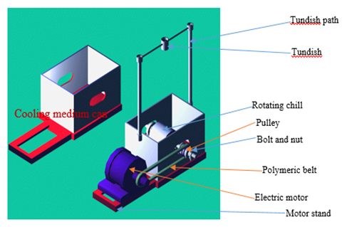
The third angle projection and geometric model of the rapid cooling machine are presented in Figures 1-2 while the fabricated rapid cooling machine is shown in Figure 3.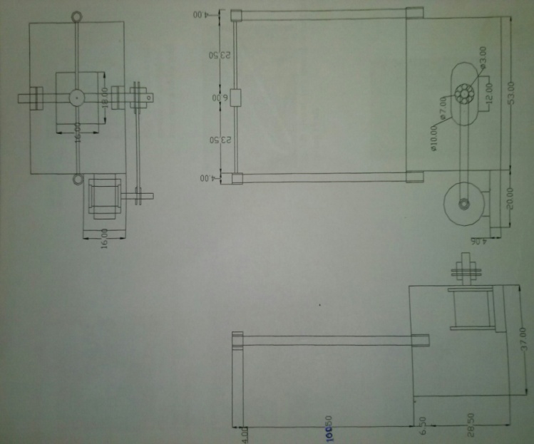 | Figure 1. Third angle projection of the rapid cooling machine |
 | Figure 2. Geometric model of rapid cooling machine |
 | Figure 3. Fabricated rapid cooling machine |
• Chemical composition of the aluminium scrapThe elemental composition of the aluminium scrap used for the production of amorphous aluminium balls is shown in Table 2.| Table 2. Elemental composition of aluminium scrap |
| | Element | % composition | | Mg | 0.018 | | Si | 0.4614 | | Mn | 0.2504 | | Be | 0.134 | | Fe | 0.00002 | | Cu | 0.014 | | Al | 99.12218 |
|
|
• XRD graphFigure 4 shows the diffraction pattern of spots or reflection reported on a screen of a laser pointer when the amorphous aluminium ball produced at 67cms-1 and rapidly cooled in water was examined with the aids of X-ray diffractometer. The chemical formulae and the angular peak or count score of the present phases were presented in Table 3. Presence of beryllium and manganese oxides is attributed to chemical reaction of beryllium and manganese with atmospheric oxygen during falling of aluminium melt droplets in air. Also, the maximum count score observed with aluminium confirmed its dominance in the ball matrix.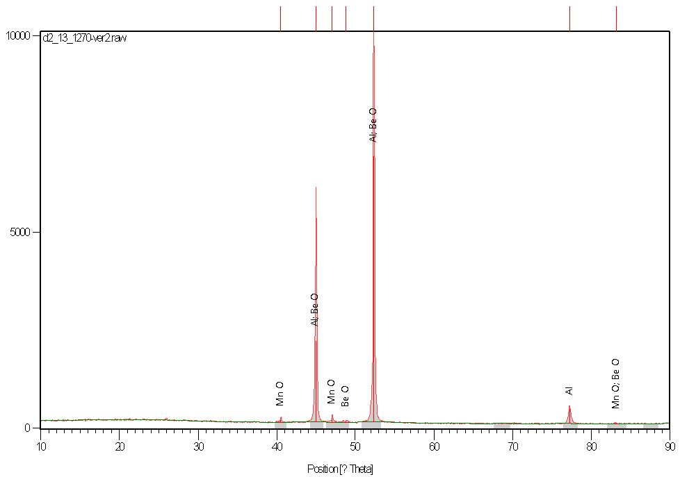 | Figure 4. XRD profile of amorphous aluminium balls produced at 67cms-1 and rapidly cooled in water |
| Table 3. Present phases in the matrix of amorphous aluminium balls produced at 67cms-1 cooled in water |
| | Score | Compound name | Chemical formula | | 62 | Aluminium | Al | | 22 | Manganosite syn | MnO | | 16 | Bromellite syn | BeO |
|
|
• Scanning electron micrographs (SEMs)Figures 5a-d show the scanning electron micrographs (SEMs) of amorphous aluminium balls. They are homogenous. Second phase particles distribute evenly within the aluminium matrix. Figures 5a-d revealed that the network of second phase particles within the aluminium matrix increased from Figures 5a-d. Also, the micrographs are very undulating and the grains are not perfectly crystalline. The degree of undulation and non-perfect crystallization of the grains increased from Figures 5a-d. This is not only attributable to very rapid solidification of aluminium melt droplets in water and brine but also the degree of solidification of each cooling medium.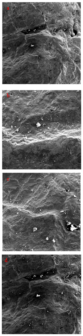 | Figure 5. SEMs of amorphous aluminium balls produced at: (a-b) 100 and 50cm mark and cooled in water; (c-d) 100 and 50cm mark and cooled in brine |
• Hardness valuesFigure 6 shows the relationship between the hardness values of the amorphous aluminium balls and the falling speeds. Figure 6 revealed that as the falling speeds of aluminium droplets incresed, the hardness values of the amorphous aluminium balls increased. Also, the hardness of brine atomisation ball is greater than that of the water atomisation ball samples. This may be attributable to increased network of second phase particles within the aluminium matrix since dislocation impingement increased as the network of the second phase particles increased.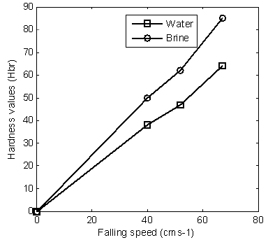 | Figure 6. Hardness values with falling speed |
• Amorphous aluminium ballsFigures 7-9 present the amorphous aluminium balls. Figures 7-9 revealed that the sizes of the balls increased as the falling speeds of the aluminium melt droplet increased. Also, the sizes of the brine atomization balls is smaller than that of water atomization balls.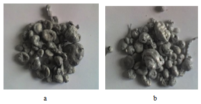 | Figure 7. Amorphous aluminium balls produced at 67cms-1 cooled in (a) water (b) brine |
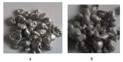 | Figure 8. Amorphous aluminium balls produced at 52cms-1 cooled in (a) water (b) brine |
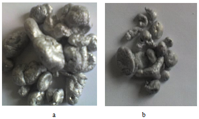 | Figure 9. Amorphous aluminium balls produced at 40cms-1 cooled in (a) water (b) brine |
5. Conclusions
From the results and discussion of this work, the following conclusions can be drawn:• The higher the falling speeds the higher the hardness of the balls.• The more severe the cooling medium is, the higher the hardness of the amorphous aluminium balls.• The brine / water atomisation is effective process in the production of aluminium balls• The research involves the conversion of off cut aluminium scrap (waste) into useful engineering materials.• These balls can used as grinding media in a mill for crushing soft polymeric materials for recycling purposes.• The recycling of waste which is the best option of solid waste management was adopted in this work.
ACKNOWLEDGEMENTS
The authors wish to acknowledge Mr Rasheed Abiodun Jimoh of department of Material Science and Engineering, Malete Kwara state, Nigeria for his support in carrying out microstructural analysis with aids of the scanning electron microscope in Material Laboratory of the university. Also appreciated is the valuable support given by the head of department of Metallurgical and Materials Engineering, Federal University of Technology Akure Ondo State Nigeria.
References
| [1] | Serope Kalpajian (1987), “Manufacturing Engineering and Technology” Addison Wesley Publishing Company, New York, 3rd edition, pp 133-150. |
| [2] | Sudarsham S. and Strivation T. S. (1990), “Rapid Solidification an Engineering Guide”www.searchdoppler.com, pp 305-330. |
| [3] | Benjamin W. N., Alan B. D. and Richard A. W. (1985), “Modern Manufacturing Process Engineering” MC Graw Hill Book Company, New York, International edition, pp 282-300. |
| [4] | Dunkley J. J. and Norval D. (2004), “Atomisation of Ferroalloys” Tenth International Ferroalloy Congress (Transformation through Technology), ISBN 0-9584663-5-1. |
| [5] | Cleary P. W. (1998), “Predicting Charge Motion, Power Draw, Segregation and Wear in Ball Mills using Discrete Element Methods” Mineral Engineering, Vol. 11, No. 11, pp 1061-1080. |
| [6] | Vladimir M., Blagoy S. and Stefan S. (2012), “Grinding in Ball Mills: Modelling and Process Control” Cybernetics and Information Technologies, Vol 12 No. 2, pp 51-68. |
| [7] | Chris M. M. and Jimmie B. (1987), “Principle, Practice and Manufacturing Management” Addison Wesley Longman Ltd, London, pp 7-9. |
| [8] | Mikell P. G. and Emery W. Z. (1987), “Computer Aided Design/Computer Aided Manufacturing” Addison Wesley Longman Ltd England, pp1-12. |
| [9] | Milner D. A. and Versaliou V. C. (1987), “Computer Aided Engineering for Manufacturing”, Kogan Page Ltd, London, pp 16-20. |
| [10] | Abhay K. (2013): “Design of Centrifugal Casting Experimental Set up for Fabrication of Alumina Tube”, Department of Ceramic Engineering, National Institute of Technology, Roukela Odisa, pp 1-36. |
| [11] | Adedipe O. and Abolarin M. S. (2011): “Design and fabrication of a Centrifugal Casting Machine”, International Journal of Engineering Science and Technology, ISSN 0975-5462, Vol. 3, No. 11, pp 8204-8210. |
| [12] | Yekinni A. A., Agunsoye J. O., Bello S. A. Awe I. O. and Talabi S. I. (2014): “Fabrication of End Quenched Machine: Hardenability Evaluation”, Journal of Minerals and Materials Characterisation and Engineering, Vol. 2, pp 107-113. |
 Abstract
 Reference
 Full-Text PDF
 Full-text HTML