Abdelmadjid Selmouni, Redouane Benzeguir, Tewfik Tamine, T. Mouhoub
Université des Sciences & de la Technologie d’Oran (USTO MB), Faculté de Génie Mécanique, B.P 1505 El-Menouar, 31000 Oran, Algerie
Correspondence to: Abdelmadjid Selmouni, Université des Sciences & de la Technologie d’Oran (USTO MB), Faculté de Génie Mécanique, B.P 1505 El-Menouar, 31000 Oran, Algerie.
| Email: |  |
Copyright © 2014 Scientific & Academic Publishing. All Rights Reserved.
Abstract
The problem of materials fatigue failure requires predictions in terms of lifespan, in order to avoid accidents of parts or structures requested in fatigue. This study aims the characterization of steel with both high and low carbon percentage in terms of thermo mechanical fatigue. After appropriate heat treatment, we proceed with rotary bending fatigue tests on smooth and with V notch samples under different temperatures for XC18 steel and X100Cr12 steel. The fatigue curves for temperatures ranging between ambient (20°C) and 350°C are presented as endurance function versus temperature function. We carried out at room temperature and 350°C.
Keywords:
Rotating bending, Fatigue, Damage, Temperature, Endurance
Cite this paper: Abdelmadjid Selmouni, Redouane Benzeguir, Tewfik Tamine, T. Mouhoub, Temperature Effect on Endurance Limit of XC18 and X100Cr12 Steel in a Rotary Bending Tests, International Journal of Materials Engineering , Vol. 4 No. 2, 2014, pp. 61-69. doi: 10.5923/j.ijme.20140402.03.
1. Introduction
As the majority of the mechanical tests are subjected to thermo mechanical loadings, it is useful to develop the predictions to make safe their operation, an effective engineering solution for the improvement of in service performance.Within this framework, various works was presented; Fedyunin and Kolomiets [1] determined the endurance limits at room temperature of St.3 steel and AMg6 samples in rotary bending.Accelerated ageing tests were carried out by Boitsov and Obolenskii [2] to quickly estimate the endurance limit. The influence of stress concentration on the endurance limit was studied by Fomichev [3]. This work takes into account the stress distribution in the defect area during the cyclic change as well as the size and the crack propagation.Shevchkov et al [4] evaluated the fatigue strength of 1424T1 alloy plates with various thicknesses used in aeronautics. Tests on samples plates containing a central hole showed that the thickness effect is weak when the stress level σmax> 170 MPa. Tests with lower maximum stress on 1.6 mm thickness plates showed an endurance limit more raised than those of 4 and 8mm thickness.Experimental methods were carried out by Maillot et al [5] to study the rupture parameters by thermal fatigue and its stabilization for AISI 304L steel. Conditions related to LMFBR method generate quickly a very dense crack network. The speed of crack initiation depends mainly on the temperature Tmax which represents the most important interval. For PWR method, the stabilization of the crack network on surface in terms of length and density appears after 400000 cycles for T=150°C.Zhu et al [6] studied the microstructure influence and the temperature effect in fatigue behavior of Al-If-Cu magnesium alloy, used in the fabrication of some car engines components. This study was used to determine the lifespan of this material for cycles close 109 by using fatigue ultrasonic measuring instruments operating at 20 kHz frequency. In this study, it was noticed that the microstructure influence on the cyclic properties is more important than the temperature effect.Tae Savoir et al [7] studied the thermal fatigue influence at high temperatures on 409 L stainless steels, 436L and 429EMSTS for temperatures ranging between 600° and 800°C. the samples thickness effect on the fatigue lifespan of these parts were taken into account.Yang et al [8] undertaken a study related to the process of crack initiation mechanism in an AZ31 alloy in fatigue mode for a very high cycle around 109. The fatigue failure appears on the surface or in the surface vicinity when the S-N curves show a decreasing and continuous tendency.Sakai et al [9] studied the temperature and moisture effects on the fatigue strength distribution of ordinary steel by carrying out statistical fatigue tests in rotary bending. The temperature was a prevalent factor in the determination of the fatigue strength distribution even if its variation were light, as envisaged in a standard atmosphere inside, whereas moisture did not have any significant effect on the fatigue strength distribution. The temperature dependence on fatigue strength distribution was quantitatively given by means of a distribution of Weibull modified by a saturated probability.Abdel-Aziz et al [10] studied the fatigue behavior of an aluminum alloy and a stainless steel in plane bending with at room and elevated temperatures. The temperature on the fatigue strength proved to be considerable parameter and in all the tests with high temperatures, the cyclic bending moment decreased.In a study carried out by Ha et al. [11], a bending fatigue strength evaluation method at high temperatures was established and SN curves for the ferritic stainless steels, such as 409L, 436L and 429EM STS, were evaluated at temperatures of 600℃ and 800℃, which is the typical temperatures of a vehicle exhaust. The endurance limit of 429EM proved to be higher than the two other stainless steels and was appreciably reduced with the increase in temperature, from 150 MPa at 600℃ to 65 MPa at 800℃.Vincent et al [12] carried out a considerable study of an uniaxial cyclic behavior of a austenitic stainless steel AISI 304L in high cycle mode at room temperature and constant amplitude loadings. In particular, the effect on the material behavior and lifespan of an average axial stress are evaluated by imposing a stress or deformation amplitude.In this paper the characterization of steel with both high and low carbon percentage in terms of thermo mechanical fatigue is investigate. After appropriate heat treatment, we proceed with rotary bending fatigue tests on smooth and with V notch samples under different temperatures for XC18 steel and X100Cr12 steel.
2. Materials and Experimental Procedures
2.1. Material
a- The XC18 steel chemical composition (wt %) used in the provided tests contains the main elements whose contents are as follows:| Table 1. Chemical composition of steel XC18 |
| | grade | C | Si | Mn | P | S | | XC18 | 0,16 à 0,22 | 0,15 à 0,35 | 0,40 à 0,70 | ≤ 0,035 | ≤ 0,035 |
|
|
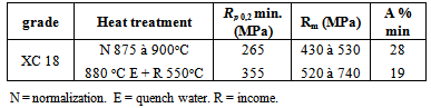
b- Mechanical properties:To carry out the rotary bending tests, we conducted pure tensile tests in order to determine the mechanical properties of used material, the mechanical properties after heat treatment were measured by tensile test on a 12mm diameter specimen. The tests were conducted on a 100T machine (figure 1). The steel test results gives:Table 2. Mechanical characteristics of steel XC18
 |
| |
|
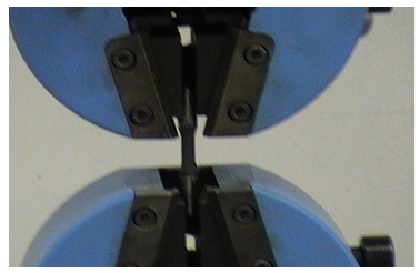 | Figure 1. Tensile test |
For X100 Cr12C steel, the chemical composition (masse %) is given in table 3, and the main mechanical properties in table 4: | Table 3. Chemical composition of steel X100Cr12 |
| | Nuance | C | Mn | Si | S | P | Ni | Cr | | X100Cr12 | 0,95 à 1,0 | ≤ 1 | ≤ 1 | ≤ 0,030 | ≤ 0,035 | ≤ 0,75 | 11 à 13 |
|
|
| Table 4. Mechanical of steel X100Cr12 |
| | grade | Rm (N/mm2) | | X100Cr12 | 1427 |
|
|
2.2. Heat Treatment
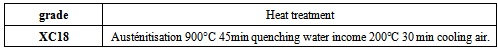
After heat treatments for both XC18 and X100 Cr12Table 5. Heat treatment of steel xc18
 |
| |
|
Table 6. Heat treatment of steel X100Cr12
 |
| |
|
The results give the following constraints of static fracture: For the application of stairs method, simples were divided into 8 lots of twelve specimens.
2.3. Specimen
The specimen shape must primarily satisfy the geometrical conditions required for fatigue test. Moreover, it should not comprise singularities leading to damage localization. The majority of fatigue failure start on the surface, the fatigue strength can be strongly influenced by the surface quality.Two kinds of rotary bending test specimens are used: a smooth cylindrical shaped (fig.2), and cylindrical shaped with a U notch (fig.3). Machining includes the turning of the useful part and a heat treatment. The purpose of this preparation is to reduce further parasitic crack priming in scratches.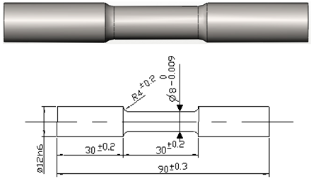 | Figure 2. Smooth cylindrical specimen |
 | Figure 3. Cylindrical specimen with U notch |
2.4. Experimental Procedure
2.4.1. Principle Testing Rotary Bending
A cylindrical-shaped specimen is installed embedded at the end. The stress is obtained by exerting a bending load of fixed direction and constant amplitude. Fatigue is generated by the part rotation and preserving fixed the bending direction. Thus, all the fibers except neutral ones are successively tended then compressed. The stresses acting on each fiber vary thus according with time following a sinusoidal law with a null medium value. Each revolution corresponds to one period or a fatigue cycle. The effort being applied in a point, the bending moment varies linearly along the specimen and is constant for a given section (Fig. 4). | Figure 4. Example of a rotary bending and distribution constraints in the relevant section of the specimen |
On the rotary bending machine, the mode of stress consists in exerting on a circular cross-section specimen in uniform rotation around its axis a bending load in amplitude and direction.The specimens and the loading arm are aligned with the rotation axis in order to eliminate the stresses due to the eccentric gyration.We put a comparator on the full part A, and then we eliminate the vibrations until the specimen turns in a concentric way. We move the comparator toward the other end of the specimen at the point B to check concentricity then we slip the loading arm on the specimen and we withdraw the comparator. The last stage consists in the installation of the weights corresponding to the fixed stress level, these weights are laid out on one hangs. The cycle counter being put at zero and for a chosen frequency, the bending test can then begin. All the tests were carried out in rotary bending under the same conditions i-e a frequency F = 50Hz and a rotational speed ω = 1300t/min. The tests were carried out on a SHIMADZU rotary bending machine, equipped with a heating furnace and an electronic programming system (Fig. 5).For different tests, the limiting lifespan was fixed by our care at 106 cycles. | Figure 5. Rotary bending machine H7 (SHIMADZU) |
2.5. Choice Test Method
There exist several more or less rigorous statistical methods, more or less long and expensive to accurately locate the endurance limit.To implement the DIXON and MOOD staircase method, it is necessary to choose stress levels regularly spaced in the vicinity of the assumed endurance limit. If the first tested specimen breaks, the following specimen is tested at the immediately lower level; in the contrary case it is tested at the immediately higher level. This process is then continued for all the specimens (60 in our case).
2.6. The Endurance Limit Assessment
The estimate of σD is given by the following formula: With +1/2 if the piece i is not broken.-1/2 if it is brokenThe standard deviation is given by:
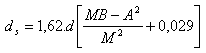
 According to Mood and other Dison, ds can be calculated if:
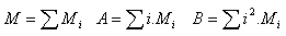
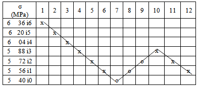
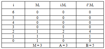
 Test results are represented in the following table 7:Note: x: broken samples, o: no broken samples s.We do the same for 8 lots.The most common phenomenon is non rupture, thus table 8 which includes the values to calculate parameters M, A and B.O: not broken samples = 3i0; σ0 = 540 MPa.i0: numbering levels.d = 16 MPa.
Table 7. Tensile test results
 |
| |
|
Table 8. Calculation of parameters M, A and B
 |
| |
|
From here you have: M = 3; A = 3, B = 5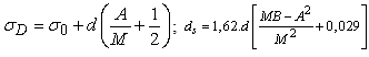
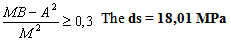 It appears according to the obtained graphs that no specimen breaks under a loading level of 556 MPa for XC18 steel. This value can be regarded as the endurance limit with approximately 4% accuracy. The figure 6 represents the lifespan curves of smooth XC18 steel specimens. A light difference is noted on the points in tests for the various temperatures, nevertheless the tendency is convergent for high cycle’s number. For the figure 7, the same remarks can be made for the notched XC18 steel samples.It is noted from figure 8, that increase in the temperature, induced a weak reduction in the endurance limit for smooth X100Cr12 steel specimens. From figure 9, it is clearly noted that the endurance limit of X100Cr12 steel notched specimens increase with the increase in the temperature. The results show that the endurance limit of X100Cr12 steel samples is higher than for steel XC18 and this for smooth and notched specimens.
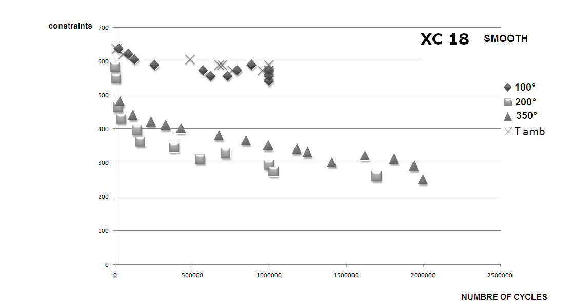 | Figure 6. Endurance limit of smooth XC18 steel specimens |
 | Figure 7. Endurance limit of cylindrical notch V XC18 steel specimens |
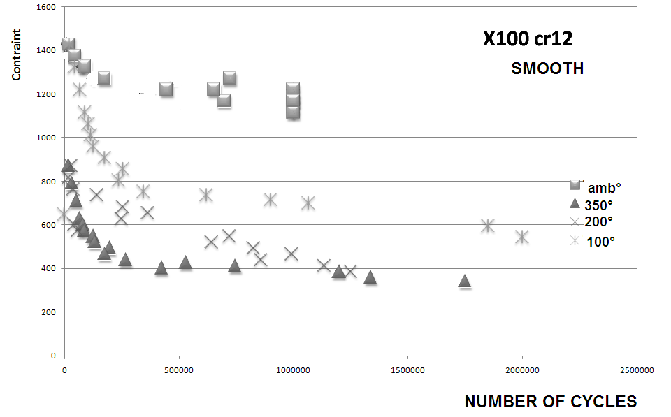 | Figure 8. Endurance limit of smooth cylindrical X100Cr12 steel specimens |
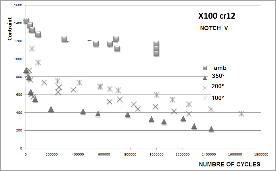 | Figure 9. Endurance limit of cylindrical notch V X100Cr12 steel specimens |
2.7. Influence of Microstructure on the Fatigue
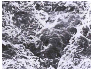
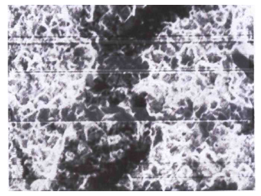
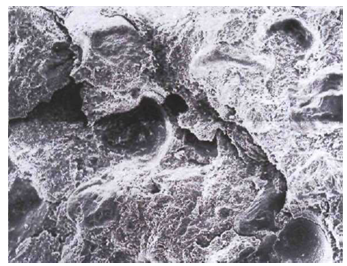
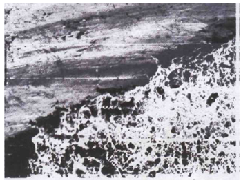
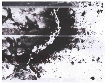
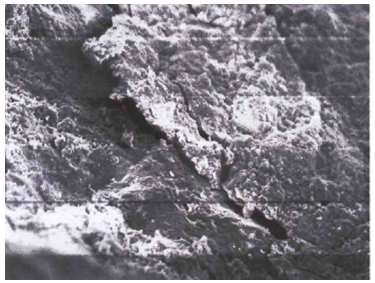
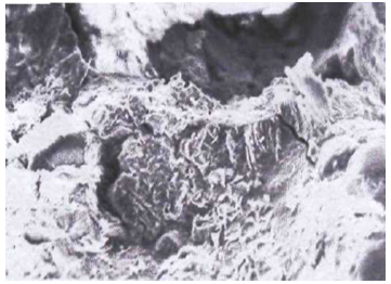
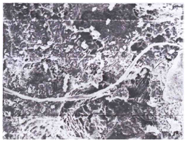
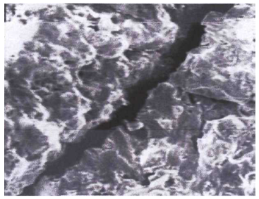
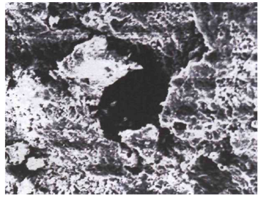
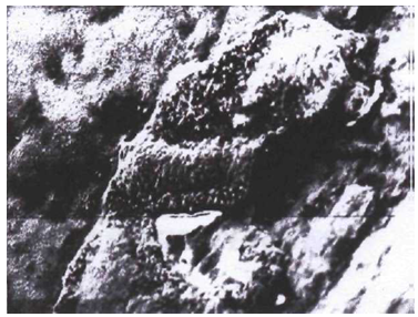
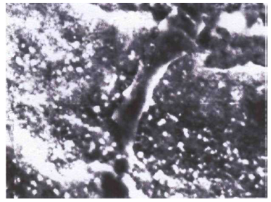
Performance of XC18 and X100Cr12High fatigue performance of XC18 and X100Cr12 is an important parameter.One way to obtain high fatigue performance is to increase the density. Also the microstructure is important for high performance XC18 and X100Cr12. An optimized process for a specific application is a combination of density and choice of microstructure.According to the breaks appearance, we can affirm that in fact fibrous breaks (V.9 stereotype) show a ductile rupture.The fracture topographies were studied thanks to the samplings subjected to chemical attacks in Nital with various contents prepared by our care at the Metallurgy laboratory. A presentation of the fracture topographies is given in the shape of stereotypes (V. 1 in V.7) for the X100Crl2 nuance and of the V.8 to the V.14 stereotype for steel XC18.While referring to V.1-V.7 stereotypes (X100Crl2, steel with high carbon content) we notice that once appeared, crack progresses and becomes unstable when the stress exceeds a critical value. In this case, the stresses at the crack edge are largely sufficient to break inter atomic connections. The plastic area is small at the crack tip, but for this fragile rupture, the crack propagation is very fast, it is catastrophic (V.7). In these stereotypes, we have a brittle fracture without plastic deformation considering high soaked carbon and undergoing an income.With SEM (the electron microscope (x2000)) study reveals that a brittle fracture according to the gaskets of the grains appears in the form of smooth surfaces which often comprises some precipitates number (stereotype V.5).The stereotypes V.8 to V.14 (XC18, slightly allied steel), are characterized by the width from the plastic area to the crack front, it moves by preceding the crack in progression, we have a low crack propagation velocity, therefore a great work volume absorbed by the crack propagation.It is noted from figure 8, that increase in the temperature, induced a weak reduction in the endurance limit for smooth X100Cr12 steel specimens. From figure 9, it is clearly noted that the endurance limit of X100Cr12 steel notched specimens increase with the increase in the temperature. The results show that the endurance limit of X100Cr12 steel samples is higher than for steel XC18 and this for smooth and notched specimens.According to the breaks appearance, we can affirm that in fact fibrous breaks (V.9 stereotype) show a ductile rupture.For all these stereotypes we have crystalline ruptures, i.e. the rupture penetrates the grain body.For V notches, the real stress at the front of the notch in the field of endurance remains lower than the elastic limit. In the presence of severe notches, the stress at the bottom of the notch exceeds the elastic limit, there are plastic deformation and work hardening of the material (front elevation in its elastic limit), stress relaxation and deformation of the profile which reduces the notch acuity and decreases the actual Kf coefficient value. There is adaptation.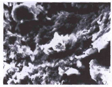 | Cliché V.l. X100Cr12 steel smooth specimen, at room temperature, N= 126300 cycles |
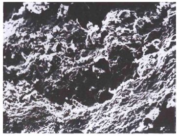 | Cliché V.2. X100Crl2 steel V notched specimen at room temperature, N= 569428 cycles |
 | Cliché V.3. X100Crl2 steel V notched specimen, at room temperature, N =67300 cycles |
 | Cliché V.4. X100Crl2 steel V notched specimen, at room temperature, N= 850000 cycles |
 | Cliché V.5. X100Crl2 steel smooth specimen at T= 200°C, N= 745651 cycles |
 | Cliché V.6. X100Crl2 steel smooth specimen, at T= 200°C, N =300600 cycles |
 | Cliché V.7. X100Cr steel V notched specimen at T= 200°C, N=971000 cycles |
 | Cliché V.8. XC18 steel smooth specimen at room temperature N = 40600 cycles |
 | Cliché V.9. XC18 steel smooth specimen, at room temperature N= 719300 cycles |
 | Cliché V.10. XC 18 steel, V notched specimen, At room temperature N= 42000 cycles |
 | Cliché V.11. XC18 steel smooth specimen at T= 200°C, N= 995000 cycles |
 | Cliché V.12. XC18 steel V notched at T= 200°C, N = 32000 cycles |
 | Cliché V.13. XC18 steel V notched specimen, at T= 200°C N=56000 cycles |
 | Cliché V.14. XC18 steel V notched specimen, at room temperature, N = 762000 cycles |
3. Conclusions
This work related to an experimental study on the fatigue behavior in rotary bending for two steels XC18 and X100Cr12. thanks to tests on a certain number of identical specimens and for various loads and temperatures, we could as much as possible characterize the fatigue behavior of these steels, by the knowledge of their endurance limit and the representing lifespan curve (Wohler curve). The staircase method was adopted for lifespan determination.The results which we found on the fatigue tests show that the presence of notch generates a stress concentration i.e. for an abrupt change in the geometry, stresses are larger and that involves that the specimen lifespan is considerably reduced. The microstructure composition has strong influence on the fatigue performance of XC18 and X100Cr12.
References
| [1] | V.N. FEDYUNIN, N.G. KOLOMIETS.-Rapid determination of endurance limit- translated from Problemy Prochnosty, N°4, pp.17-20, April, 1975. |
| [2] | B.V. BOITSOV, E.P. OBOLENSKII. – Accelerated tests of determining the endurance limit as an efficient method evaluation the accepted design and technological solutions –Institute of Engineering, Moscow. Translated from Problemy Prochnosty, N°10, pp.23-28, October, 1983. |
| [3] | P.A. FOMICHEV. – Method of calculating the endurance limit of specimens with a stress concentrator.- Kharkov.K.E. Zhukov Aviation Institute. Translated from Problemy Prochnosty, N°11, pp. 84-86, November, 1989. |
| [4] | E.I. SHEVCHKOV, T.D. ROSTOVA, V.V. ZAKHAROV and A.V. DEMIDENKOV.- Cyclic endurance of sheets from alloy 1424 with different thicknesses – Metal science and heat treatment, Vol.43, Nos.3-4, 2001. |
| [5] | V. MAILLOT, A. FISSOLO, G. DEGALLAIX.- Thermal fatigue crack networks parameters and stability an experimental Study- International Journal of Solids and Structures 42 (2005) 759-769, August 11, 2004. |
| [6] | X.ZHU, A.SHYAM, J.W. JONES, H.MAYER, J.V. LASECKI, J.E.ALLISON Effects of microstructure and temperature on fatigue behavior of E319-T7 cast aluminum alloy in very long life cycles – International Journal of Fatigue 28 (2006) 1566-1571, April 4, 2006. |
| [7] | TAE KNOW HA; HYO TAE JEONG, HWAN JIN SUNG.- High temperature bending fatigue behavior of stainless steels for automotive exhaust.- Journal of Materials Processing 187-188 (2007) 555-558. |
| [8] | F.YANG, S.M. YIN, Z.X. LI, Z.F. ZHANG.- Crack initiation mechanism of extruded AZ31 magnesium alloy in very high cycle fatigue regime.- Materials Science and Engineering A, FEBRUARY 2008. “PDCA12-70 data sheet,” Opto Speed SA, Mezzovico, Switzerland. |
| [9] | T. Sakai, M. Ramulu, M. Suzuki “Temperature and humidity effects on fatigue life distribution of carbon steel” Volume 13, Issue 2, March 1991, Pages 117–125,J. Padhye, V. Firoiu, and D. Towsley, “A stochastic model of TCP Reno congestion avoidance and control,” Univ. of Massachusetts, Amherst, MA, CMPSCI Tech. Rep. 99-02, 1999. |
| [10] | H.A. Abdel-Aziz, J.H. Lamble, W. Johnson «Low-endurance fatigue of an aluminum alloy and a stainless steel in plane bending at ambient and elevated temperatures». |
| [11] | Ludovic Vincent, Jean-Christophe Le Roux, Said Taheri “On the high cycle fatigue behavior of a type 304L stainless steel at room temperature” International Journal of Fatigue 38 (2012) 84–91. |
 Abstract
 Reference
 Full-Text PDF
 Full-text HTML