Hicham Lotfi, Ali Moudden, Bouazza Faiz
Laboratory of Metrology and Information Processing, Ibn Zohr University, Faculty of Sciences, B. P. 8106, Agadir, Morocco
Correspondence to: Hicham Lotfi, Laboratory of Metrology and Information Processing, Ibn Zohr University, Faculty of Sciences, B. P. 8106, Agadir, Morocco.
| Email: |  |
Copyright © 2012 Scientific & Academic Publishing. All Rights Reserved.
Abstract
The work presented in this paper treat the durability of reinforced concrete structures, the experiments performed in the laboratory are carried to determine the depth and the diameter of rod coated by concrete. To study these structures we have developed a non-destructive technique based on ultrasonic signals backscattered from the samples analyzed. The experimental protocol of this technique is adapted to evaluate the parameters measured. The determination of the group velocity of the wave backscattered by circumferential of cylindrical rods in iron coated with concrete, allows detecting the diameter and depth of these rods in the building structure.
Keywords:
Group Velocity, Rod in Iron, Reinforced Concrete, Depth
Cite this paper: Hicham Lotfi, Ali Moudden, Bouazza Faiz, Ultrasonic Evaluation of the Depth and the Diameter of the Rods of Reinforced Concrete, International Journal of Materials Engineering, Vol. 3 No. 2, 2013, pp. 17-27. doi: 10.5923/j.ijme.20130302.02.
1. Introduction
Control tests of reinforcement structures are different, we find the measurement of electrode potential for the reinforcement corrosion rate, the measurement of the speed of corrosion to evaluate the loss of a section of the steel according to the time, the electrical capacitance to measure humidity and locate the wet surface. The properties of the concrete are evaluated by measuring the compressive strength and bending machines presses. Try these methods and are partially or totally destructive, because they leave impacts and holes in the structure and the information obtained is not local.The use of Non-Destructive Testing (NDT) techniques, for emission of ultrasonic waves, has opened new opportunities on the side of quality control and the study of the mechanical properties of materials. The study of propagation of elastic wave in solids is a possible way to examine some physical properties of cementitious materials. Aggelis et al.[1] characterized with two non-destructive methods the surface of the concrete, the first method is to control the thermal variation of the temperature, and the second is the use of the propagation of ultrasound to estimate the depth of defects in the concrete. Ismail et al.[2] Have studied the degradation of concrete resulted by to long-term actions by measuring the compressive strength by non-destructive and destructive tests. Malagavelli [3] studied the strength and workability of concrete by using different super plasticizers constituents.To improve the control of civil engineering works, we develop a non-destructive investigation technique (NDT) based on the analysis of the backscattered signal by cylindrical rods of iron used in the reinforcement structures. This paper discusses two main objectives. The first objective is to assess accurately the ultrasonic response of cylindrical rods of different diameters by determining the group velocity of surface waves backscattered along the circumference of the rods. The second is to improve the knowledge on the influence of diameters and depths of these rods in the coating structure on the ultrasonic propagation.
2. Samples Preparation
The samples are prepared in wooden molds parallelepiped with dimension  . In these molds, we place an iron rod at a given depth, then we coat with concrete. After a week of hydration we proceed to release these molds to obtain samples of reinforced concrete with a single frame. These samples are then emerged in a tank filled with water and excited with a transducer of central frequency is 0,5MHz. This transducer is put a distance equal to 2cm of the sample. The duration of the emission of waves should be sufficient to avoid undesired echoes of experimental equipment. The experimental tank is filled with water of the density
 , and the velocity of the ultrasonic wave in water is
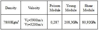
  .Iron frames used in the cementitious materials as form of high-strength. Rods are completely surrounded along its length by ribs forming almost spirals in its surface. Theses rods are the main materials used in the formwork. In table 1, we present the mechanical characteristics of cylinders iron (rods) used in this study. In figure 1, we represent the geometry of the reinforced concrete.
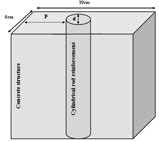 | Figure 1. Geometry of the sample |
Table 1. Mechanical properties of iron
 |
| |
|
3. Principle of the Experiment
3.1. Experimental Setup
Figure 2 shows the experimental setup used for the experiments. This setup consists of an ultrasonic transducer of 0,5 MHz, which function as the transmitter and receiver. This transducer is emerged in a cubic tank filled with water where the sample was placed at 2cm from the transducer. The ultrasonic transducer is connected to a pulse generator type (Model 5073 Sofranel PR, Sofranel Instruments) which sends the electric signal to the digital oscilloscope (Hewlett Packard HP). The digital oscilloscope is connected to a microcomputer by a GPIB cable in order to processes the signal not available on the oscilloscope and analyzes the variables determined.The control begin with the acquisition of signals represented on the screen of the oscilloscope and backscattered by different structures (reinforced concrete) by using application made by the graphical programming language LabVIEW. The samples prepared are structures of mortar (concrete) reinforced by cylindrical rods of iron. The circumference of the rods is of the order of the wavelength 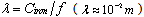 .
.
3.2. Technique of Control
The experimental study of geometric waves, backscattered by solid cylinders, was studied by M.de Billy[4], and has been continued to this day by different researchers work. These studies showed the validity of the theory of geometrical optics. Especially the prediction of the echoes observed during the diffusion of a cylinder full who their elastic properties and geometric are known. Experiences of non-destructive testing realized by ultrasound are performed by the technique of reflection of ultrasonic waves[5]. The measurements were performed on samples with mass ratios water / cement  and cement / sand
  . These samples were prepared with Portland Cement CPJ 45 produced by Agadir factory. The iron rods coated with mortar (concrete) are those sold by vendors of building products.Thanks to this technique, we study the ultrasonic response of the cylindrical rod of diameter equal 6mm according to their depths (d = 2, 4 and 6 cm) in the concrete layer. Rods with diameters 8 and 10mm are not studied resulted by their complicated geometric. They are completely surrounded along its length by ribs forming almost a spiral. Figure 4 shows the type of temporal signals obtained by the oscilloscope in the case of normal incidence 0°. In figure 3 we schematize the path of the backscattered wave surface along the circumference of a solid cylinder (rod).The series of echoes
  and
and  observed in figure 4 is corresponding to successive roundtrip of the wave surface along the circumference of the rod. The echo
  is the reflection in the perimeter of the cylindrical rod and water [6]. This signal is obtained in the backscatter geometry, where the ultrasonic transducer functions as transmitter and receiver of ultrasonic signal. The time between two successive echoes may be related to the radius
  of the cylindrical rod and the group velocity
  of the surface wave by the following equation:
  | (1) |
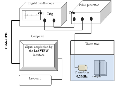 | Figure 2. Experimental setup |
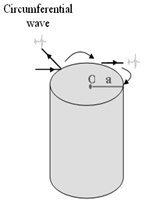 | Figure 3. Circumferential (surface) wave on a solid cylinder |
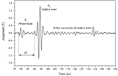 | Figure 4. Type of signals backscattered by a cylindrical rod, d=6mm |
4. Study of the Ultrasonic Response of the Rods Immersed in Water
4.1. Temporal signal
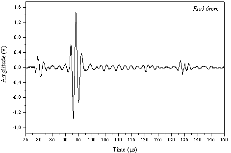
Diffusion of a plane wave by cylindrical and spherical diffusers has been presented several times in the literature. The most studied is the one presented by Faran[7] for the case of the cylinder and sphere. Long expressions in the case of the cylinder were reformulated in matrix form by Doolittle and Überall [8]. Then, the applications were done by Maze et al.[9] and Ripoche et al.[10] on the diffusion of ultrasound plane waves by a solid cylinder that excited normally on its axis, they showed that these waves are strictly influenced by the propagation of surface waves. Later on, Maze et al.[11] have shown that the velocity of these waves is dependent of the frequency of wave and the radius of the target. In figure 5 we represent the temporal signal backscattered by the iron rod of diameter equal 6mm, we remark that the first two echoes diffused by the rod are clearly.
4.2. Spectral Amplitude Backscatterted
The theoretical results obtained by Überall et al.[12], and Ugincius and Überall[13] show that the complex structure of the obtained wave is related to the circumferential wave propagation (Rayleigh wave) which form standing waves on the circumference of the target (cylinder, sphere ...). To obtain the spectral amplitude and phases of the echo we apply the Fast Fourier Transform (FFT) to the temporal signals. The rods studied are excited normally to their axis by means of a transducer of central frequency 0,5 MHz and bandwidth from 0,2 to 0,8 MHz. The spectrum backscattered by the rod of diameter equal 6mm is shown in figures 6.
4.3. Group Velocity 
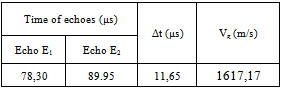
The velocity of the propagation of ultrasonic waves in solids is an important property that is used, for example, in non-destructive evaluation to calculate the rigidity of materials. Conventional techniques used to perform velocity measurements in material need to know the thickness of the material studied and the time of the reflected echoes between two interfaces limiting the material. In table 2 we represent the group velocity calculated by the equation (1) for the rod of diameter equal 6mm. The time between two echoes, due to reflection of the surface wave, is determined.Table 2. Group velocity Vg of circumferential wave diffused
 |
| |
|
 | Figure 5. Temporal signal backscattered by the rod, d=6mm |
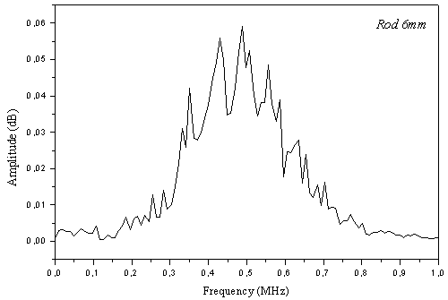 | Figure 6. Spectral amplitude backscattered by the rod,d= 6 mm |
5. Application to the Reinforced Concrete
Reinforced concrete occupies a large part of their mechanical properties and their frames. The first network reinforcement is located a few centimeters deep below the surface (between 2 and 6 cm). This concrete layer, called concrete cover, is contact directly with the external environment and submitted of damages. The main role of this layer is to protect these frames against aggressive agents from the environment surrounding the structure (air, water, ions ...)[14]. It is therefore important to determine the characteristics of this layer of concrete (ultrasonic velocity, depth...).The methods using the non-destructive mechanical wave propagation in concrete can be used to obtain information on different scales (millimeter, centimeter…) depending on the wavelength used. The acoustic waves can also be used to detect cracks, voids, or measure thicknesses. The information provided by these methods is important.
5.1. Ultrasonic Velocity of Concrete
5.1.1. Geometry of the Problem
The concrete structure is prepared in molds thickness of 6cm. The description of the preparation of these samples is described in paragraph 2. The schema in figure 7 shows the path of different signals backscattered by the concrete. These samples are located at a distance of 2 cm with the transducer.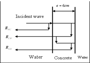 | Figure 7. Signal path in the concrete layer |
Figure 8 shows a type of ultrasonic signals backscattered by a concrete structure of rectangular geometry and thickness equal 6cm (Figure 7). This signal comprises a main echo  corresponding to reflection of the incident wave on the interface between water and the first plane of the concrete. Then secondary echoes,
  which is the reflection of the wave incident on the interface between the second plane of the concrete and water and the echo
  corresponds to a roundtrip of the wave in the thickness of the concrete.
5.1.2. Calculate of Ultrasonic Velocity of Concrete
Control by measuring the velocity of the ultrasonic wave is one of nondestructive testing commonly used to evaluate building materials. Chekroun et al.[15] measured ultrasonic velocity and attenuation to determine the quality and rigidity of the concrete. Then they evaluated the sensitivity of these parameters with the mechanical properties of concrete. Evaluation of concrete, based in aggregate crushed, with ultrasonic velocity was studied by Carcaño and Moreno[16].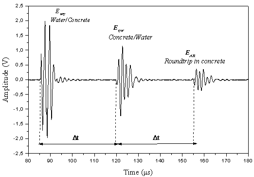 | Figure 8. Types of signals backscattered by a concrete structure |
Thanks to the piezoelectric transducer the electrical energy emitted is converted into mechanical energy. The ultrasonic transducer detects the time of each echo in each interface of concrete and water, knowing the thickness e of the concrete, it is possible to determine the group velocity of wave in concrete, and it is expressed by the formula (2): | (2) |
 is the variation time between echoes
 and
and  , and e is the thickness of the concrete
  . Therefore the ultrasonic velocity in concrete is
  .
. | Figure 9. Types of signals backscattered by a reinforced concrete, p = 2cm (6mm) |
5.2. Echoes of Signal Backscattered by the Concrete
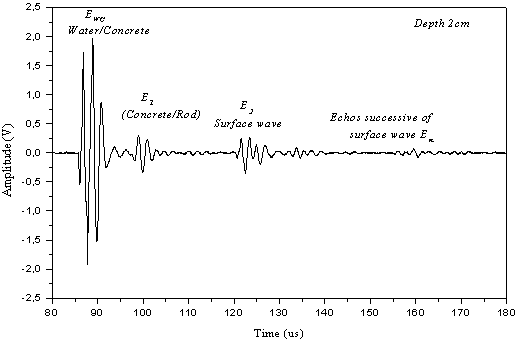
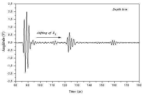
Figure 9 represents a type of the signals obtained for the rod coated by concrete. The length of reinforced concrete equals a 10 cm. This signal comprises a main echo  about 8.25 μs, which corresponds to the reflection of the incident wave on the interface between water and the first plane of the concrete. Echo
  , which corresponds to the reflection between the concrete and a point on the perimeter of the rod. Echo
  , which is appropriate to a roundtrip of the surface wave around the circumference of the rod. Finally the echoes
  corresponding to successive reflections of the surface wave by the circumference of rod. Comparing the position of the echo
  in figures 9, 10 and 11, we remark that the echo
  moves to the position of echo
  , when we varying the depth of rod into the concrete layer.
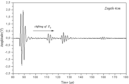 | Figure 10. Signal backscattered by the reinforced concrete, p = 4cm (6mm) |
 | Figure 11. Signal backscattered by the reinforced concrete, p=6cm (6mm) |
 | Figure 12. Comparison of measured and selected depth |
5.3. Depth of Rod in Concrete
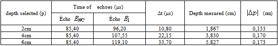
The iron frames used in civil engineering as frames of building whereby we obtained the reinforced concrete. They are introduced into the concrete to improve the resistance of slabs, beams and structures of buildings. The diameter and depth of frames in concrete can ensure the rigidity and quality of the coating structures in terms of the nature of the iron used. The use of ultrasound appears as a solution for determining the depth of the rods in the concrete and to evaluate their diameters. The use of ultrasonic waves can also locate the rods iron, identify damaged areas or cracks near the surface of the concrete and evaluating the thickness of a concrete structure.Knowing the ultrasonic velocity in concrete (paragraph 5.1.2), and from the temporal signal backscattered by the concrete, we determine the time between two echoes, respectively due to reflection at the interface water / concrete and concrete / rod. Accordingly, the depth of the rod in the structure is determined by the following relation:  | (3) |
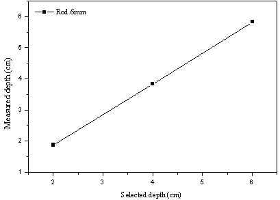
Table 3 shows the results obtained for the different structures of the diameter 6mm and depth chosen. The difference  is the variation between the selected depth and measured depth. In average value, the difference is about 0,158 cm for the rod of diameter 6mm.For all samples made the thickness of the layer of concrete cover is fixed and invariable equal a 10cm. The acquisitions made with a transducer to assess the variation depth of rod coated. The figure 12 shows a comparison between the chosen depth and measured depth. We note that this curve is linear. Therefore the group velocity of ultrasonic wave is a very important for determining the depth of the rod in concrete layers.
 Table 3. The depth determined of the rod in concrete cover
 |
| |
|
5.4. Spectral Amplitude of the Echo 
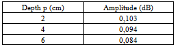
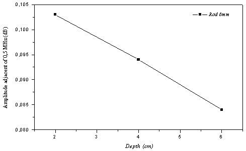
In this paragraph, we will represent the spectral amplitude obtained from filtering the echo  that reflected on the circumference of the cylinder coated with concrete. For this we isolate the echo in its time domain, and we determine the backscattered spectrum. The figure 13 illustrates the variation of the spectral amplitude in function of frequency. The interpretation of these curves allows observing the influence of the depth of the rod in structure of concrete. We also remark that the spectral amplitude is reduced with increasing of depth of the cylindrical rods, and these spectral amplitudes are almost the same bandwidth and their maximum correspond to the value of 0,5 MHz, who is exactly the central frequency of transducer used, which indicates that there is no dispersion. In table 4 we represent the values of the maximum of spectral amplitude for each signal backscattered in each depth. The figure 14 shows the variations of the spectral amplitude in function of the depth of rod 6mm in concrete.
Table 4. Maximum of spectral amplitude adjacent of 0,5 MHz, rod 6mm
 |
| |
|
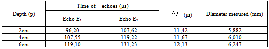
5.5. Diameter of the Rod Coated
Table 5 shows the variations of time  between echoes
  and
and . The diameter of the rod is determined from the relation (4)
  | (4) |
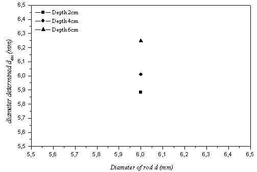
In figure 15 we represent the diameter determined in function of diameter of rod 6mm. We remark that the diameters determined are near to the diameter of the rod 6mm. Therefore, this result allows us to do reverse resolution in order to determine the diameter of the rod coated with concrete. It is therefore clear that we could easily distinguish between the rods used in construction building based on the measurement of group velocity of circumferential waves backscattered by the rods coated. Comparing the diameters determined for the two cases (coated or insulated rods) shows that the concrete cover does not have a great influence on the circumferential waves backscattered by rods coated.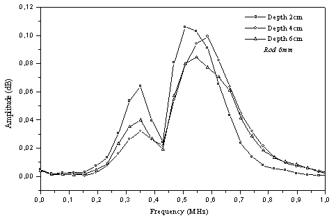 | Figure 13. Backscattered spectrum, rod 6 mm coated with concrete |
 | Figure 14. Variation of the spectral amplitude in function of the depth of |
 | Figure 15. Diameter determined  in function of diameter of rod d in function of diameter of rod d |
Table 5. Diameters determined when the rods are coated
 |
| |
|
6. Conclusions
For an analysis of reinforced concrete, we have developed a technique of non-destructive investigation to study the signals backscattered by cement structures reinforced by iron rods. This method is based on the analysis of temporal signal backscattered by various structures of reinforced concrete. Measuring the group velocity of surface waves backscattered by the circumference of the rod allows determining its diameter and the depth in the layer of concrete.The results show that the use of ultrasonic waves can evaluate the concrete cover and locate rods in concrete, by determining their diameters (thicknesses) and depth in the concrete.
References
| [1] | D.G. Aggelis,E.Z. Kordatos, M. Strantza, D.V. Soulioti, et T.E. Matikas. “ NDT approach for characterization of subsurface cracks in concrete”. Construction and Building Materials, Volume 25, Issue 7, Pages 3089–3097, 2011. |
| [2] | M.Ismail, B.Muhammad, E.Ismail.” Compressive strength loss and reinforcement degradations of reinforced concrete structure due to long-term exposure”. Construction and Building Materials, Volume 24, Issue 6, 898–902 , 2010. |
| [3] | Venu Malagavelli and Neelakanteswara Rao Paturu "Strength and Workability Characteristics of Concrete by Using Different Super Plasticizers". International Journal of Materials Engineering (SAP) 2012; 2(1): 7-11. |
| [4] | G.Quentin, M. de Billy, A.Hayman. “Comparison of backscattering of short pulse solid spheres and cylinders at large ka”. J.Acoust.Sco.Am, 70, 870-878. 1981. |
| [5] | Faiz. B, Maze.G, Decultot. D, Aassif. E and Ezzaidi. M. “Ultrasonic characterization of the quality of an epoxy resin polymerization”. IEEE Trans. Ultrasonics, Ferroelectrics ,and frequency control, vol. 46, 188-196. 1999. |
| [6] | Pascal Rembert,” Etude des résonances acoustiques par des méthodes quasi harmoniques et impulsionnelles phase spéculaire ". Doctorat thesis, University of Le Havre, Page 207. 1991. |
| [7] | J.J. Faran.” Sound scattering by solid cylinders and spheres”. J. Acoust. Soc. Am. , 23(4) 405–418, 1951. |
| [8] | R.D. Doolittle and H. Uberall.” Sound scattering by elastic cylindrical shells”. J. Acoust. Soc. Am, 39(2). 272–275, 1966 |
| [9] | Maze.G, Marical.S and Lecroq.F. “Diffusion d'une Onde Acoustique Plane Par Des Sphéroïdes”, J. Phys. Colloques 51, C2-419-C2-422. 1990. |
| [10] | Ripoche. J, Maze.G, and Izbicki J.L. “A new acoustic spectroscopy: Resonance spectroscopy by the MIIR”. J. Non destructive Evaluation, vol. 5, no. 2, pp. 69-79. 1985. |
| [11] | Maze G, Ripoche J, Derem A and Rousselot J L. “ Diffusion d'une onde ultrasonore par des tubes remplis d'air immergés dans l'eau”. Acustica, pp 55- 69. 1984. |
| [12] | Überall, H., Dragonette, L. R., Flax, L., J. Acoust.Soc. Amer. 61 711. 1977. |
| [13] | Ugincius and H. Uberall. “Creeping-Wave Analysis of Acoustic Scattering by Elastic Cylindrical Shells”. J. Acoust. Soc. Am., Vol. 43. page 1025. 1968. |
| [14] | P.E. Grattan-Bellew.” Microstructural investigation of deteriorated Portland cement concretes”. Construction and Building Materials, 10(1):3–16, 1996. |
| [15] | M. Chekroun, L. Le Marrec, O. Abraham, O. Durand, and G. Villain.” Analysis of coherent wave dispersion and damping for non-destructive testing of concrete”. Ultrasonics, Volume 49, Issue 8, pages 743–751. 2009. |
| [16] | Rómel Solís-Carcaño et Eric I. Moreno. “ Evaluation of concrete made with crushed limestone aggregate based on ultrasonic pulse velocity”. Construction and Building Materials, Volume 22, Issue 6, Pages 1225–1231. 2008. |
 Abstract
 Reference
 Full-Text PDF
 Full-text HTML