-
Paper Information
- Next Paper
- Previous Paper
- Paper Submission
-
Journal Information
- About This Journal
- Editorial Board
- Current Issue
- Archive
- Author Guidelines
- Contact Us
International Journal of Materials Engineering
p-ISSN: 2166-5389 e-ISSN: 2166-5400
2012; 2(6): 90-104
doi: 10.5923/j.ijme.20120206.04
Fracture Behavior of the Cement Mantle of Reconstructed Acetabulum in the Presence of a Microcrack Emanating from a Microvoid
 Abstract
 Reference
 Full-Text PDF
 Full-Text HTML
D. Ouinas1, A. Flliti1, M. Sahnoun1, S. Benbarek2, N. Taghezout3
1Laboratoire de modélisation numérique et expérimentale des phénomènes mécaniques, Department of Mechanical Engineering, University Abdelhamid Ibn Badis, Mostaganem, 27000, Algeria
2LECM, Department of Mechanics, Faculty of Engineering, University of Sidi-BelAbbes, 22000, Algeria
3Department of Computer Science, University of Es-Senia Oran, BP 1524, El-M' Naouer, 31000, Oran, Algeria
Correspondence to: D. Ouinas, Laboratoire de modélisation numérique et expérimentale des phénomènes mécaniques, Department of Mechanical Engineering, University Abdelhamid Ibn Badis, Mostaganem, 27000, Algeria.
| Email: |  |
Copyright © 2012 Scientific & Academic Publishing. All Rights Reserved.
In this work, the finite element method is used to analyze the behavior of the crack emanating from a microvoid in acetabular cement mantle by computing the stress intensity factor. A simple 2D multilayer model developed by Benbarek et al.[1] to reproduce the stress distributions in the cement mantle has been used. To provide the place of birth of the crack, the stress distribution around the microvoid is determined in several positions for three different loads. The effect of axial and radial displacement of the microvoid in the cement is highlighted. The results indicate that the stress distribution 
 and
and  induced in the cement around the microvoid are not homogeneous and this, whatever its position. In addition, there is a large birth risk of cracks in several radial directions depending on the position of the microvoid in the cement mantle. The crack can be triggered in several directions in mode I or mode II, while the mixed mode is dominant. The KI and KII SIF varies according to the position of the microcrack and the microvoid in the cement. They increase proportionally with the increase of the weight of the patient. It should be noted that the KI SIF are two times higher than the SIF KII. The maxima of the KI SIF are obtained for the position of the microvoid α = 100° and θ = 45° of the microcrack and the risk of the propagation of the microcrack is very important for this orientation.
Keywords: Bone cement, Acetabulum, Microvoid, Microcracks, Stress Intensity Factors, Finite Element Analysis
Cite this paper: D. Ouinas, A. Flliti, M. Sahnoun, S. Benbarek, N. Taghezout, "Fracture Behavior of the Cement Mantle of Reconstructed Acetabulum in the Presence of a Microcrack Emanating from a Microvoid", International Journal of Materials Engineering, Vol. 2 No. 6, 2012, pp. 90-104. doi: 10.5923/j.ijme.20120206.04.
Article Outline
1. Introduction
- Although the Polymethylmethacrylate has long been known as a fixative in orthopedics dental prostheses, its first use in hip arthroplasty in 1962[2]. Despite the various disadvantages of PMMA, improved techniques of preparation and implementation of cement and implementation methods contributes to the survival of cemented arthroplasties. In addition, the function of fixing the implant, the bone cement is responsible for transferring the loads of the joint to the bone. Face loads transmitted, which can reach in some circumstances eight times the weight of the patient[3,4], bio-competence cement must be good[5].Thus, the mechanical and physical properties of cement are determining in the service life of the implant[6,7]. These properties are strongly affected by the size and number of pores in cement[8]. Indeed, the porosity can cause crack initiation by fatigue, by creating irregular areas[9,10]. Thus, surgeons tend to reduce the porosity to ensure greater resistance to fatigue.Gold, that this trend is directly related to the chosen method of mixing during the preparation of cement[11]. For example, the conventional method of mixing leads to a porosity ranging from 5 to 16% depending on the type of cement, while the method of "vacuum mixing" generates a porosity of 0.1 to 1%[12,13]. Some authors assume that the latter method, increases the mechanical properties largely due to the decrease in micropores and macropores[14, 15], thus improving the life of the cement[16,17].The effect of the position and orientation of a crack in the cement in three loads using the finite element method has been studied by Serier et al.[18] and Bachir Bouiadjra et al.[19]. They indicate that, for the third case load, the risk of crack propagation is higher when the crack is in the horizontal position for both failure modes. Achour et al.[20] presented a study on the mechanical behavior of the damage (failure) of the interface between the cement / bone and cement / stem in total hip prosthesis. They conclude that interfacial crack (cement / bone) in the distal region can spread by opening and shear; it can cause a risk of brutal fracture if the crack length exceeds 0.6 mm.The objective of this study are expected to shed light on the influence of the presence of microvoid and a crack emanating from the microvoid on the fracture behavior of bone cement, by using finite element method. The effect of the position of the microvoid in cement and effect of the size of the microcrack on the fracture behavior are highlighted. The stress intensity factor to the microcrack-tip is used like criterion of rupture. The analysis of the distribution of the Von Mises stresses in the various components of the acetabular part and the implant is made to a zero angle between the necks of the implant relative to the axis of the cup. We are required to develop a finite element model to analyze the presence of a microvoid on the behavior and strength of bone cement
2. Geometrical Model
- The geometrical model is generated from a roentgenogram of a 4mm slice normal to the acetabulum through the pubic and ilium. The cup has an outer diameter of 54 mm and an inner diameter of 28 mm. It is sealed with the bone cement mantle to uniform thickness of 2 mm[23]. The inside diameter of the UHMWPE cup is 54 mm. The interfaces between the cup-cement and cement-subchondral bone are assumed to be fully bonded. In this work two cases were analyzed: the first is to take the presence of a microvoid in different positions in cement. The stress concentrations are determined. In the second case we assume initially the propagation of a microcrack emanating from the microvoid in the determined position and characterized by a high stress concentration gradient; and another time it is assumed that the microcrack emanating from the microvoid in different positions. The stress intensity factors are evaluated. The model was divided in seven different regions (Figure 1) according to the different elastic constants with isotropic properties considered in each region. The main areas are: cortical bone, subchondral bone and spongious bone [24-28]. The femoral head was modeled as a spherical surface that was attached to the spherical acetabular cavity. The acetabular cavity is located on the outside of the hip bone at the junction of its three components (Figure 1): ilium, ischium and pubic bone. Table 1 summarizes the material properties of cement mantle, cup and all sub-regions of acetabulum bone.
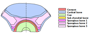 | Figure 1. Composition of the acetabulum[24] |
3. Finite Element Modelling
- The acetabulum was modeled using the finite element code Abaqus 6.11.1[30]. To simplify the study, the 2D model of the acetabulum was considered. This representation was used to be representative of a section taken through the transverse plane of the acetabulum. Bergmann[25] found that the variation of the resultant forces acting on the acetabulum is larger in the transverse plane. A very fine discretization was used to represent all possible, and to be closer to reality, and special mesh type ¼ was used near a microcrack tip. Figure 2 shows the mesh of the geometrical model. The geometrical model consists of 20611 elements in total, 13564 quadratic elements of type CPS4R and 7047 triangular elements of type CPS3. We opted for an orientation defined by an angle of 0° between the implant neck and the axis of the cup. The latter reflects a posture of the human body.
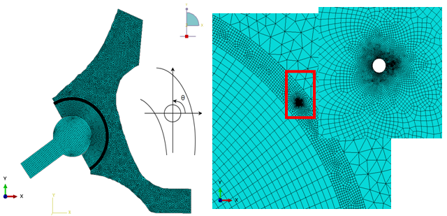 | Figure 2. Geometrical model Mesh |
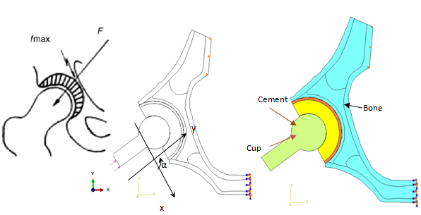 | Figure 3. Load model |
- A limited amount of research has been done on the distribution of the loads acting on the acetabulum caused by the transfer of the force inducted by the femoral head. In a study Bergmann et al.[31] have measured maximum values of the resultant of the forces applied to the hip of 584% of the body weight for jogging at 7 km/h for a man of 82 years (height: 1.68 m, weight 650 N) and 870% of body weight for stumbling a woman of 69 years (height 1.60 m, 470 N). For reasons to be in the worst case, we chose a zero inclination angle between the neck of the implant and the axis of the cup (see Fig. 3) which was used by Benbarek et al.[1] whose they indicate that they present more stress concentration. The considered Body weight is 70, 140 and 210 kg. The sacroiliac joint was completely stationary while the pubic joint was free in the sagittal plane. The boundary conditions considered are shown in the configuration of Figure 3, pubic nodes are blocked in all directions, on the wing of the ilium the nodes are blocked along the x axis and a uniformly distributed load applied on the implant. The contact between the bone and cement and between the cement and the cup was taken as fully bound, and between femoral head and the cup was assumed to be without friction under small slip.
4. Results and Analysis
4.1. Variation of Von Mises
- Before analyzing the stress intensity factor at the microcrack tip, it is necessary to analyze the stress distribution around the microvoid to predict the microcrack initiation. In Figures 4-1, 4-27, we plotted the variation of Von Mises stresses as a function of the standardized size of the contour of the microvoid located in different positions in the bone cement. The positions of the angle
 are taken at 0°, 20°, 40°, 70°, 90°, 100°, 120°, 150° and 170°. For each angle
  of the microvoid nine axial positions are taken from the cup-cement interface head to the cement-bone interface-subchondral bone (compact bone beneath the cartilage resistant). The Von Mises stresses are plotted for three load cases, a weight of 70kg, 140kg and 210kg. The normal weight of the patient can be multiplied according to these activities, in walk state, rising and descending stairs.In Figures 4.1-4.3 we see that the maximum Von Mises stresses are obtained in the middle positions of the cavity. They are becoming increasingly important with the importance of patient weight.It is clear that the stress distribution is not uniform around the microvoid. We note several peaks in each radial position of the microvoid. All these stresses are due to the compression effect produced by the weight of the patient. At the radial position corresponds to
  the maximum stress at the interface is cup-cement of the order of 20MPa and the bone-cement interface subchondral is of the order of 35MPa. The first interface to the second interface stress changes from single to double, this shows that when the microvoid is close to the bone-cement interface subchondral interaction effect is much larger than when it is close to the interface head cup-cement. The maximum stresses in the microvoid near the interface cement / bone sub-chonral into position
  are of the order of 35MPa, 70MPa and 140MPa, respectively for the weight of 70kg, 140kg and 210kg. This shows the effect of the interaction between the microvoid and the interface. In these three cases the maximum stress exceeds the tensile failure, which shows the severity of the defect position in the cement. In addition, depending on the axial position of the microvoid, the constraints become important. From the position P1 where the cavity is close to the cup-cement interface, the maximum stress increases progressively to approach the interface cement-subchondral bone. This finding is significant regardless of the radial position of the microvoid. The stress levels at the radial position of microvoid
  are respectively 7, 3, 5.2, 1.75, 3, 9, 30 times higher than the radial positions
  and
and respectively. This shows that if the microvoid is in positions
  it presents a high risk compared to other radial positionsExcept for the radial position at
  , the curves show four zones of stress concentration. The areas characterized by the highest concentrations are obtained at positions
  and
and  , that is to say the bottom of the microvoid. The other two zones are at positions
  and
and  . It should be noted that when the microvoid is in radial positions at
  , the Von Mises stresses are very low compared to other positions. At the radial position
  the maximum stresses are very important and this is the fact that the microvoid is located between the cup and the cortical bone.
4.2. Stress Variation  on the Contour of the Microvoid
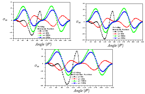
- In addition, it is necessary to analyze numerically by the finite element method the levels and distribution of the main constraints on the contour of the microvoid. Figures 5.1-5.3 show the intensity and the stress distribution around this defect for several positions in the cement and a position of the implant. It should be noted that in the positions 0° and 180°, the stresses
 are null whatever the applied load (70kg, 140kg and 210kg). The curves are antisymmetric with respect to the x axis of the cavity that is to say with respect 180 °. The maximum stresses are obtained for the position of the cavity at 100°. At 120°, the stresses are similar to those marked 100°. The two peaks maximum stress positive are at 60 ° and 240 ° and the two peaks of the compressive stress are in 120 ° and 300 °.The maximum compression stresses are important for the position of the microvoid null, this is due to the edge effect. Such a position of the microvoid in cement, fact of increasing strongly the risk of damage. Thus, when the patient's weight exceeds 100kg, any position of the microvoid can lead to rupture of the cement in the first cycles of activity and therefore to the destruction of the hip prosthesis.
4.3. Stress Variation  on the Contour of the Microvoid
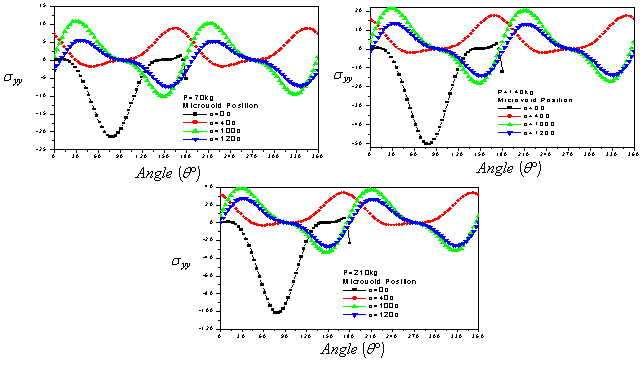
- In Figures 6.1-6.3, we show the evolution of the stress
 on the contour of the microvoid for different positions in cement. It is clear that gaits are antisymmetric with respect to 180°. For all cases, the tensile stresses in the near vicinity of the microvoid are small compared with the compressive stresses at the position
  When the weight P=70 kg, the maximum compressive stress
  is about four times lower of the compression fracture limit, while the traction is three times lower, which shows that they are relatively low. By against, a weight of 140kg and the position of the microvoid to 100°, the constraints tend to the tensile strength limit to angles 30° and 210°. The stress
  greatly exceeds the strength in tension and compression. In this case, the cement is almost fragmented in tension or compression depending on the position of the microvoid in the binder.
4.4. Stress Variation  on the Contour of the Microvoid
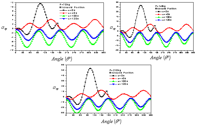
- Figures 7.1-7.3 show the variation of the shear stress on the contour of the microvoid for different positions in the cement. We note that the positions of the cavity to 100 ° and 120 ° have four peaks of compression. The positions 0 ° and 40 ° have four peaks of tension. However, the highest compression stresses are obtained for the position of the cavity to 100 ° and are of the order of 8 MPa, 15 MPa and 30 MPa, respectively for the applied loads 70kg, 140kg and 210kg. The tangential stresses are increasingly important with the importance of the applied load. The positive shear stresses are maximum for the position of the cavity at 0°; they reach 12 MPa. In this case, the risk of birth of microcrack in mode II can occur in one area, whereas the position of the cavity at 100 ° can be in four positions if the load is large, which increases the likelihood of damage to the cement. The lower stresses are obtained for the positions 40 ° and 120°. In comparison with the stresses
 and
and  the tangential stresses are low to create a microcrack mode II.
4.5. Stress Variation in the Contour of the Cement
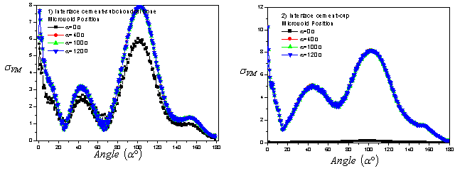
- In Figures 8.1 and 8.2 we plot the variation of stresses in the interfaces cement/bone subchondral and cement-cup in the presence of a microvoid of 0.02mm diameter in the radial positions at 0°, 40°, 100° and 120° and in middle of the cement. The applied load is of the order of 70 kg. It should be noted that the presence of the cavity has an effect on the change in the stress at the two interfaces. By against, the Von Mises stress is greatest in areas well clear in contours interfacials. The areas most stressed are in the position
 and in the interval varying from 90° to 120° in both interfaces.The first peak is obtained at 0° and the second at 100° for the two interfaces of the cement. In this case, the Von Mises stresses are almost three times less to tensile strength stress. It should be noted that if a microvoid is in these two areas of peak stress, the defect will quadruplicate the stress and therefore present a high risk of microcrack initiation, and the likelihood of its spread is high. The Von Mises stresses are higher in the cup/cement interface that in the cement interface-subchondral bone and it explains that the cement is a stress absorber. If a cavity is close to the interface, the stresses in the interface and the cavity will be increased as a result of interaction and therefore the risk of damage is major. This behavior shows that the existence of the microvoid is a source of increasing stress concentrations and consequently the risk of loosening of the prosthesis
5. Variation of SIF of Microcrack Emanating from the Microvoid
- In this section we have studied the evolution of the stress intensity factor KI and KII as a function of the length of the microcrack emanating from the microvoid located in the bone cement. This latter is taken in the most unfavorable radial positions previously established. Three patient's weight loads are considered, 70kg, 210kg and 140kg. In addition, we chose the radial positions with the concentrations of Von Mises stresses are maximum for angles
 and
and  The positions of the maximum stresses on the contour of the microvoid whose a microcrack is susceptible to propagate are the angles
  and
and  respectively
  and
and  According to figures 9.1-9.6, we find that the stress intensity factors KI and KII will vary as a function of the increase in the length of the microcrack emanating from the microvoid. This variation is more marked with increasing of patient weight. The stress intensity factors KI for the positions of the microvoid 40° are positive and for positions 0° are negative. While KII SIF are negatives whatever the microvoid position. We note that the SIF KI and KII obtained for the position
  of the microvoid are much larger in absolute value compared to other positions, showing that the birth of a microcrack emanating from a cavity at an angle
  constitute a high risk of rupture compared with other positions. This is due to the edge effect. The KII SIF is almost ten times smaller than the KI except for the case of load 70kg, where it is almost negligible for large microcracks. In position
  , the KI SIF shows significant positive values that can cause rupture of the cement easily. This microvoid position affects significantly the bone-cement fracture toughness, which controls the failure process at the interfaces.In Figure 10 we present the Von Mises stress levels for four different orientations
  and
and  the microvoid in cement. It shows the mapping stress of the microcrack tip emanating from the microvoid located in the bone cement. It is clear that stresses vary depending on the microvoid position. In Figures 11.1-11.6 we plotted the variation of KI and KII SIF as a function of the microcrack length in the second position containing the maximum stresses on the Von Mises contour of the microvoid to the angles
  and
and  respectively
  and
and  It is clear that the SIF of oriented microcrack in the second position are low compared to the first position. In this case the KII SIF changes sign, it is positive for
6. Influence of the Orientation of the Microcracks from the Microvoid on the SIF
- In Figures 12.1-12.6, we have shown the variation of the stress intensity factor KI and KII as a function of the microcrack orientation emanating from a microvoid located in the cement. The microvoid takes several critical positions, 0°, 40°, 100° and 120° for three different loads of the patient. The SIF KI and KII vary as function of the microcrack and the microvoid positions in the cement. They increaseproportionally with the increase of the weight of the patient. It should be noted that the SIF KI are two times higher than the SIF KII. The maximum values of KI FIC are obtained for the position of the microvoid α = 100° and of the microcrack θ = 45°.The risk of propagation of the microcrack is very important for this orientation. The minimum values are respectively θ = 135 ° and θ = 310°. The maximum values for SIF KII are obtained for the position of the microvoid α = 100° and θ = 90°, θ = 290° respectively of the microcrack. The minimum value is at θ = 160°. It should be noted that there is a position for which the SIF KI and KII are null, this corresponds to the interval
 . The same behavior has been marked when the microvoid is at the position α = 120°. If the microvoid is at the position α = 40°, the microcrack is susceptible to propagate in pure mode I at θ = 135° or at θ = 335° or pure mode II at θ = 20° or θ = 170°. And if it is at 0°, the SIF KI reaches its maximum negative at 0 ° and 335 ° for the SIF KII.
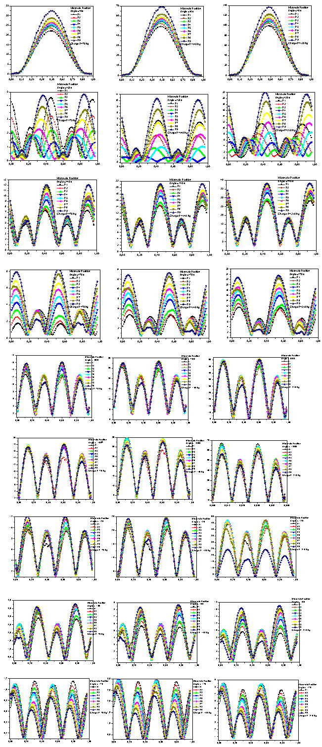 | Figure 4. Variation of Von Mises stress on the microvoid contour located in the bone cement in different positions and different loads. |
 | Figure 5. Variation in the  stress on the microvoid contour stress on the microvoid contour |
 | Figure 6. Variation in the  stress on the microvoid contour stress on the microvoid contour |
 | Figure 7. Variation in the  stress on the microvoid contour stress on the microvoid contour |
 | Figure 8. Variation of Von Mises stress contours on the bone cement |
 | Figure 9. Variation of KI and KII SIF vs. microcrack length emanating from the microcavity in the bone cement (position 1) |
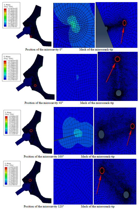 | Figure 10. Variation of stress levels at the microcrack-tip and the microcavity located in the bone cement |
 | Figure 11. Variation of KI and KII SIF vs. microcrack length emanating from the microcavity in the bone cement (position 2) |
 | Figure 12. Variation of SIF of microcrack emanating from a microcavity according to the angle |
7. Conclusions
- This study was conducted to analyze the fracture behavior of bone cement in the presence of a microvoid and a microcrack emanating from the microvoid. Results emerge the following findings:→The distribution induced by stresses
 ,
,  and
and  in the cement around the microvoid are not homogeneous and this whatever of its position. The maximum stresses
  are obtained respectively for the positions of the cavity at 100° and 120°.→The stresses are null at positions 0° and 180°. Two peaks of maximum stress are positives at 60° and 240° and two peaks of the compressive stress are at 120° to 300°. The
  stresses are antisymmetric with respect to 180 °. For all cases, the tensile stresses at the near vicinity of the microvoid are small compared with the compressive stresses at the position of
  The variation of shear stress on the contour of the microvoid is periodic. However, the highest compression stresses are obtained for the position of the cavity at 100 ° and are relatively low in comparison with the stresses
  and
and  →The presence of the cavity has an effect on the variation of the stress at the interfaces cement-cup and cement-subchondral bone. The Von Mises stress is maximum in the most stressed areas are in the position
  and in the interval ranging from 90° to 120° in both interfaces. Two peaks of maximum stress: at 0° and 100°. The Von Mises stresse are higher in the interface cement-cup that in cement-subchondral bone interface.→If a cavity is close to the interface, the stress in the interface and the cavity will be amplified under the interaction effect and therefore the risk of damage is major. This behavior shows that the existence of the microvoid in the cement will be a source of multiplication of stress concentrations and therefore the loosening of the prosthesis.→The risk of the initiation of cracks in the cement is important when the microvoid is close to the bone-cement interface. The amplification is greater when it is at an angle
  →The SIFs KI and KII increase with increasing of the microcrack length emanating from the microvoid. This increase is even more marked with increasing patient weight. The SIF KI for the positions of the microvoid
  are positive and for positions
  are negative. The risk is major with the presence of two cracks.
References
| [1] | S. Benbarek, B. Bachir Bouiadjra, T. Achour, M. Belhouari, B. Serier. Finite element analysis of the behaviour of crack emanating from microvoid in cement of reconstructed acetabulum. Materials Science and Engineering A 457 (2007) 385–391. |
| [2] | J.CHARNLEY. Low friction arthroplasty of the hip. Theory and practice. Springer Verlag, Berlin, Berlin, 1979 |
| [3] | G. Bergmann, F. Graichen, A. Rohlmann. Hip joint loading during walking and running, measured in two patients. J Biomechanics, 1993, vol. 26 no.8 p969–90 |
| [4] | Berme N, Paul JP. Load actions transmitted by implants. J Biomed Eng. 1979, 1 p 268–272 |
| [5] | D. Ouinas, B. Bachir Bouiadjra, B. Serier, N. Benderdouche, A. Ouinas, Numerical analysis of Brazilian bioceramic discs under diametrical compression loading. Computational Materials Science 45 (2009) 443–448. |
| [6] | SR. Goldring, AL. Schiller, M. Roelke, CM. Rourke, DO. O’Connor, WH. Harris. Formation of a synovial-like membrane at the bonecement interface. J Bone J Surg;A65:575-84, 1983. |
| [7] | M. Jasty, WJ. Malony, CR. Bragdon, DO. O'Connor, T. Haire, WH. Harris. The initiation of failure in cemented femoral components of hip arthroplasties”. J Bone Joint Surg;B73: 551-8, 1991. |
| [8] | N. Passuti, F. Gouin. Les ciments aux antibiotiques dans la chirurgie orthopédique. Revue du rhumatisme 70: 371–378, 2003. |
| [9] | RSM. LING, JC. LEE. Porosity reduction in acrylic cement is clinically irrelevant. Clinical Orthopedics, 355, 249-253, 1998. |
| [10] | DW. Janssen, J. Stolk, N. Verdonschot. Why would cement porosity reduction be clinically irrelevant, while experimental data show the contrary? 50th Annual Meeting of the Orthopaedic Research Society. San Francisco, USA, p 3, 2004. |
| [11] | W. Macaulay, CW. DiGiovanni, A. Restrepo, KJ. Saleh, H. Walsh, LS. Crossett, MG. Peterson,S. Li, EA. Salvati. Differences in bone-cement porosity by vacuum mixing, centrifugation, and hand mixing. J Arthroplasty 2002; 17:569–575 |
| [12] | U. Linden, J. Gillquist. Air inclusion in bone cement. Importance of the mixing technique. Clin Orthop 1989; 247:148–51 |
| [13] | JS. Wang, F. Kjellson. Bone cement porosity in Vacuum Mixing system. In: Walenkamp GHIM, Murray DW (eds) Bone cements and Cementing technique. Springer, Berlin Heidelberg New York Tokyo, pp 81–95, 2001. |
| [14] | S. Wang, H. Franzén, E. Jonsson, L. Lidgren. Porosity of bone cement reduced by mixing and collecting under vacuum. Acta Orthop Scand 64(2):143–46, 1993. |
| [15] | S. Wang, S. Toksvig-Larsen, P. Müller-Wille, H. Franzén. Is their any difference between vacuum mixing systems in reducing bone cement porosity? J Biomed Mater Res (Applied Biomaterials) 33:115–19, 1996. |
| [16] | WP. Yau, TP. Ng, KY. Chiu, KC. Poon, WY. Ho, DK .Luk. The performance of three vacuum mixing cement guns- acomparison of the fatigue properties of Simplex P cement. International Orthopaedics 25:290–293, 2001. |
| [17] | JM. Wilkinson, R. Eveleigh, AJ. Hamer, A. Milne, AW. Miles, I. Stockely. Effect of mixing technique on the properties of acrylic bone cement. J Arthroplasty 15:663–7, 2000. |
| [18] | B. Serier, B. Bachir Bouiadjra *, S. Benbarek, T. Achour. Analysis of the effect of the forces during gait on the fracture behaviour in cement of reconstructed acetabulum. Computational Materials Science 46 (2009) 267–274. |
| [19] | B. Bachir Bouiadjra, A. Belarbi, S. Benbarek, T. Achour, B. Serier. FE analysis of the behaviour of microcracks in the cement mantle of reconstructed acetabulum in the total hip prosthesis. Computational Materials Science 40 (2007) 485–491. |
| [20] | T. Achour, M.S.H. Tabeti, M.M. Bouziane, S. Benbarek, B. Bachir Bouiadjra, A. Mankour. Finite element analysis of interfacial crack behaviour in cemented total hip arthroplasty. Computational Materials Science 47 (2010) 672–677 |
| [21] | A. Flitti, D. Ouinas, B. Bachir Bouiadjra, N. Benderdouche. Effect of the crack position in the cement mantle on the fracture behavior of the total hip prosthesis. Computational Materials Science 49 (2010) 598–602 |
| [22] | M.M. Bouziane, B. Bachir Bouiadjra, S. Benbarek, M.S.H. Tabeti, T. Achour. Finite element analysis of the behaviour of microvoids in the cement mantle of cemented hip stem: Static and dynamic analysis. Materials and Design 31 (2010) 545–550. |
| [23] | J. Tong, K.Y. Wong, Mixed Mode Fracture in Reconstructed Acetabulum, Department of Mechanical and design Engineering, University of Portsmouth, Anglesea road, Portsmouth, PO1 3 DJ, UK. |
| [24] | Christipher, Peter, Ken, Bachus, Marcis, Craig, Higginbotham, J. Arthroplasty, 16 (2001) 2. |
| [25] | G. Bergmann, F. Graichen, A. Rohlmann. Hip Joint Loading During Walking and Running, Measured in Two Patients. J. Biomech. 1993;26(8):969–990. |
| [26] | A. Phillips, Finite Element Analysis of the Acetabulum after Impacting Grafting, The University of Edinburgh, School of civil and environmental Engineering. Crew Building, Kings Buildings, Edinburgh EH93JN. |
| [27] | C. Li, C. Granger, H. Del Schutte Jr., S.B. Biggers Jr., J.M. Kennedy, R.A. Latour, Failure Analysis of Composite Femoral Components for Hip Arthroplastiy, Department of Bioengineering and Department of Mechanical Engineering, Clemson University, Clemson,SC. |
| [28] | C. Delaunay, Prothèse totale de Charnley o`u en est aujourd’hui le «le Gold-Standard» de l’arthoplastie primaire de hanche, Clinique de l’Yvette – 91160 longjumeau. |
| [29] | D. Foucat. Effets de la présence d’un alliage métallique au sein du ciment de scellement des cupules des prothèses totale de hanche. Etude mécanique et thermique. Thèse doctorat-2003.ULP_ INSA Strasbourg – ANGES – URS. |
| [30] | K. Sorensen, Abaqus user manual 6.9.11. |
| [31] | G. Bergmann, F. Graichen, A. Rohlmann. Hip joint loading during walking and running, measured in two patients. Journal of Biomechanics, 1993, Vol. 26, 969-990. |