-
Paper Information
- Previous Paper
- Paper Submission
-
Journal Information
- About This Journal
- Editorial Board
- Current Issue
- Archive
- Author Guidelines
- Contact Us
International Journal of Materials Engineering
p-ISSN: 2166-5389 e-ISSN: 2166-5400
2012; 2(5): 67-74
doi: 10.5923/j.ijme.20120205.02
Finite Element Model of Crack Growth under Mixed Mode Loading
 Abstract
 Reference
 Full-Text PDF
 Full-Text HTML
Souiyah Miloud 1, A. Muchtar 2, A. K. Ariffin 2, Malek Ali 1, M. I. Fadhel 1, Basem Abu Zneid 3
1Faculty of Engineering & Technology (FET), Melaka, 75450, Multimedia University (MMU)
2Faculty of Engineering & Built Environment, Bangi, 43000, University Kebangsaan Malaysia (UKM)
3Universiti Teknologi Malaysia Skudai, 81310, Johor Bahru
Correspondence to: Souiyah Miloud , Faculty of Engineering & Technology (FET), Melaka, 75450, Multimedia University (MMU).
| Email: |  |
Copyright © 2012 Scientific & Academic Publishing. All Rights Reserved.
In this paper, in order to predict the crack growth trajectory and to evaluate the SIF under mixed modes (I & II), one proposes a new finite element program for crack growth using the source code written in FORTRAN. The finite element mesh is generated using an advancing front method, where the generation of the background mesh and the construction of singular elements are also added to this developed programme to facilitate the crack process and the fracture analysis. Displacement Extrapolation Technique (DET) was employed to evaluate the SIFs under mixed mode loading conditions. Therefore, the accuracy of both SIF`s values and the crack path predictions results are compared and validated with other relevant published research work. However, the assessment indicated that this developed finite element programme is reliable and robust to evaluate the SIFs and predicts the crack trajectories successfully based on the applied loading conditions.
Keywords: Linear Elastic Fracture Mechanics, Adaptive Refinement Mesh, Stress Intensity Factors, Finite Elements Method, Crack Propagation
Cite this paper: Souiyah Miloud , A. Muchtar , A. K. Ariffin , Malek Ali , M. I. Fadhel , Basem Abu Zneid , "Finite Element Model of Crack Growth under Mixed Mode Loading", International Journal of Materials Engineering , Vol. 2 No. 5, 2012, pp. 67-74. doi: 10.5923/j.ijme.20120205.02.
Article Outline
1. Introduction
- Structural failure can be generally associated with one or more fracture of the materials making that structure. In fact, fracture mechanics deals with the irreversible process of rupture due to nucleation or sudden crack and crack growth. The influence of cracking on the structural strength has been widely appreciated since the end of the 19th century. However, some aspects of its nature and influence still remain unknown[1]. The use of crack propagation laws based on stress intensity factor range is the most successful engineering application of fracture mechanics. In the elastic fracture analysis, the stress intensity factors sufficiently define the stress field close to the crack tip and provide fundamental information of how the crack is going to propagate. Basically, the estimation methods can be categorized into two groups, those based on field extrapolation near the crack tip and those which make use of the energy release when the crack propagates. The latter group includes the J-contour integration, the virtual crack extension and the strain energy release rate method. The main disadvantage of these methods is that the stress intensity factor components, KI and KII in mixed mode problems are either impossible or very difficult to be separated. Nevertheless, the first groups which are based on near-tip field fitting procedures require finer meshes to produce a good numerical representation of crack-tip fields generated to facilitate the calculation.
2. Finite Element Model
- Most established research was on computer base by applying numerical methods which were mostly uses commercial software such as;[2] an enriched partition of unity finite element method (PUFEM), which is known as one of the meshless method to calculate the SIF in LEFM under plane stress and plane strain condition. Another, numerical examples were performed to evaluate the generated stress intensity factors directly from the scaled boundary finite element solution for the singular stress field[3]. More recent work was developed variational mesh-free method, to evaluate the stress intensity factors of mixed mode crack problems, using the element free Galerkin method[4]. Accordingly, another new method was proposed to determine the SIFs for the indentation problem based on the conservation integral[5]. In contrast, Numerical experiments were conducted to evaluate the effectiveness of two proposed techniques on near crack tip singularity[6]. In fact, an observation was stated that a general theoretical model for automatically evaluating the increments of crack growth during a loading process does not exist yet[7]. Experiments work on a central crack specimen with holes, to predict the crack path and to evaluate the mixed mode stress intensity factors (KI & KII)[8]. Somehow, this limit nowadays still characterizes the computer codes for crack growth simulation in elastic and elasto-plastic materials. Generally, the software should address three different aspects of the problem, specifically are; (i) SIFs evaluation, (ii) the crack propagation direction, and (iii) mesh modification to accommodate the crack advancement. The first and second aspects can be solved with no particular difficulties and many commercial FE codes have built-in capabilities to evaluate the SIF. The last aspect is much more complex and is rarely solved by FE codes, e.g. FRANC2D, FRANC3D and ZENCRACK[9]. Eventually, the FE model is modified in order to accommodate the obtained evaluation on short and straight crack propagation directions. The whole process is repeated many times and both is time-consuming and a source of errors if it is performed manually. This is particularly true for the mesh modification. However, software on the other hand, is capable in handling the solution process in an automatic way.However, in the current study, we developed a new finite element programme for crack growth using the source code written in FORTRAN. In order to predict the crack growth trajectory and to evaluate the SIFs under mixed modes (I & II) loading in the frame of LEFM. The displacement extrapolation techniques with the adaptive refinement mesh method are used, to determine the stress intensity factors on two different geometries. Specifically are; four points bending plate and, centre double cracked plate with two-holes. Additionally, the obtained results of the current study are evaluated and validated with other relevant experimental and numerical results selected from the literature.
2.1. Generation of Singular Element
- An unstructured triangular mesh is automatically generated by employing the advancing front method. The singular elements have to be constructed correctly to get a proper field of singularity around the crack tip as shown in Fig. 1.
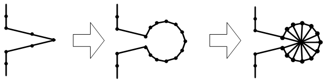 | Figure 1. The cut and patch procedure of generating singular elements around a crack tip |
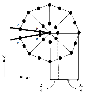 | Figure 2. A typical arrangement of the natural triangle quarter-point elements around a crack tip |
2.2. Mesh Generation and Adaptive Refinement Mesh
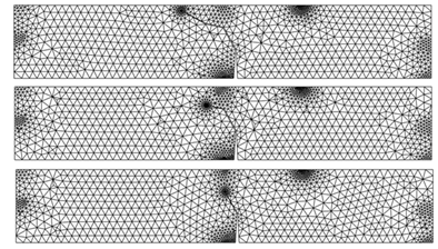
- In general, the smaller mesh size gives more accurate finite element approximate solution. However, reduction in the mesh size leads to greater computational effort. The adaptive mesh refinement is employed as the optimization scheme. This scheme bases on a posteriori error estimator which is obtained from the solution from the previous mesh. Basically, the success of the adaptivity in overall is depends to a large extent on the efficient coupling between the error estimator, refinement scheme and automatic mesh generator. The importance of these adaptive techniques in practical applications has led to a considerable research on fully automatic mesh generators that require only the specification of the boundary and mesh size distribution over the domain. An example of geometry shows the whole process of generating the mesh is illustrated in Fig.3.
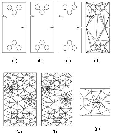 | Figure 3. The mesh generation stages |
 | (1) |
 | (2) |
 | (3) |
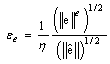
 the size of the element is reduced and vice versa. (iv) The new element size is determined as
 | (4) |
2.3. The Displacement Extrapolation Technique
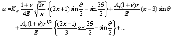
- One of the simplest and most frequently used methods is displacement extrapolation technique[18]. It consists typically in the effective SIF concept by which, the fracture evaluation can be easily carried out[19]. The crack length was evaluated by linear-elastic analysis from the compliance of single-edge-notched specimen in three-points bending test[20]. A new finite element of quasi-static brittle fracture was developed, based on computational framework for three-dimensional cracks propagation bodies. They uses consistent thermodynamical framework for crack propagation in elastic solids[3].The asymptotic expression for the displacement normal to crack plane, v under mode I loading[21]:
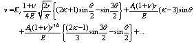 | (5) |
 are the polar coordinates defined at the crack tip.
 | (6) |
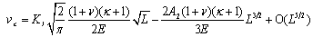
 . Particularizing for nodes b and c on the singular element at the upper face of the crack yields:
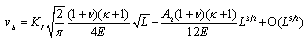 | (7) |
 | (8) |
 | (9) |
 | (10) |
 | (11) |
 | (12) |
 | (13) |
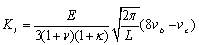
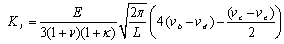
 . The nontrivial solution is given by
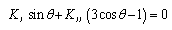 | (14) |
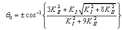 | (15) |
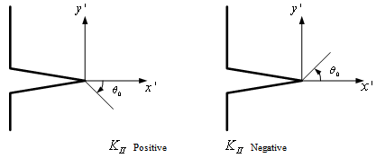 | Figure 4. Sign of the propagation angle |
 should be opposite to the sign of
  [19]. The two possibilities are illustrated in Fig. 4.The criterion for crack to propagate from crack tip is based on the material toughness,
  . If the calculated stress intensity factor,
  then the crack will propagate to the direction
  expressed by Equation (11). The crack increment length
  is taken 10%-20% of the initial crack length
  , inversely proportional to the ratio of
  . The ratio represents the mixed mode proportionality, therefore shorter increment length should be taken to carefully justify the crack path curvature when
  is relatively large compare to
  [13]. Thus the crack length increment is approximated by the Lagrange interpolation as:
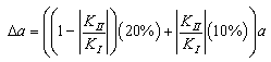 | (16) |
3. Numerical Analysis and Validation
- A developed finite element model of crack growth for brittle materials has been employed on four points bending geometry and, double centre cracked plate with two holes under mixed mode loading conditions.
3.1. Four Points Bending Geometry
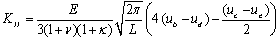
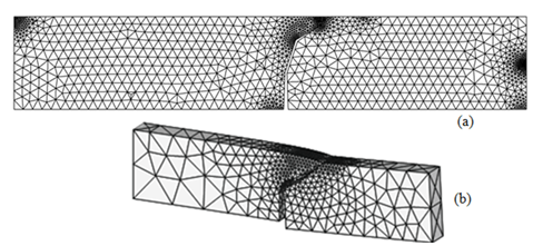
- having the dimensions of B = 2 mm, W = 5 mm and length > 43 mm, made of Al2O3-Ceramics. An enlargement of mesh around crack tip represented the elements around the crack tip is illustrated in Fig.3. Four points bending geometry with final adaptive mesh are shown in Fig. 5.The stresses in this loading case were also computed. The geometric functions of FI and FII as follows[22]:
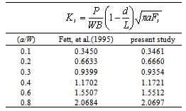
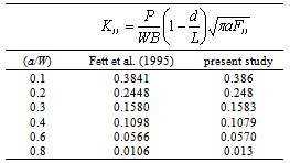
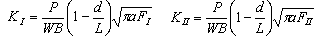 | (17) |
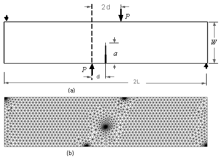 | Figure 5. (a) Four-point bending geometry and (b) the final adaptive mesh |
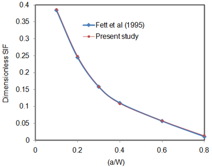
 ), are tabulated in Table 1 and Table 2 with d/W = 0.5. The dimensionless form of the estimated stress intensity factor was obtained by using Eq. (17), presented for the range of 0.1 < a/W < 0.4.
|
|
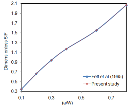 | Figure 6. Dimensionless SIF vs. (a/W) for mode I |
 | Figure 7. Dimensionless SIF vs. (a/W) for mode II |
 | Figure 8. Comparison results of the crack trajectory; (a) current study (b) Gürse & Miehe[3] |
 | Figure 9. Three steps of crack propagation direction of four-point bending geometry |
3.2. Center Double cracked Plate with Two-Holes under Mixed Mode Loading
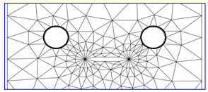
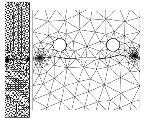
- A complicated mixed mode fracture problem was studied to demonstrate the performance of the developed programme on double centre cracked plate with two holes. The geometry and its final adaptive mesh are shown in Fig. 10. Meanwhile, the enlargement of the rosette around both crack tips is shown in Fig. 11.
 | Figure 10. The geometry and its final adaptive mesh |
 | Figure 11. The enlargement of the rosette around both crack tips |
 and
and  as illustrated in Fig. 12.In the beginning, the crack exhibited a pure Mode I state, which increased the KI values, whereas in Mode II state,
  values became lower so that the crack curved closely to the left side of the hole and then curved downwards where
  and
and  tended to decrease. Therefore, when the crack direction declined from both holes with the curvature, both
  and
and  decreased. However, when the crack growth linearly
  tended to increased again whereas,
  decreased. Furthermore, based on this phenomenon, it could be understood that Mode I significant effect than Mode II, and this was due to the brittleness of this material.
 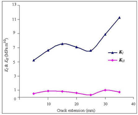 | Figure 12. The relationship of KI & KII with crack extension |
 | Figure 13. Numerical result of the crack path for the CCT specimen with two holes |
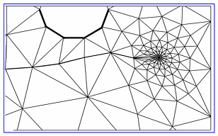 | Figure 14. Current work results of an enlargement of a crack trajectory for the CCT specimen with two holes |
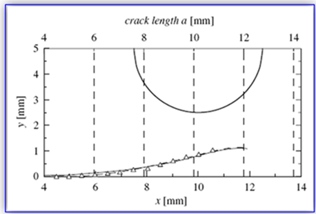 | Figure 15. The triangle points correspond to experimentally obtained crack path, where the full line holds for one parameter and the dash line for two parameter fracture mechanics[8] |
4. Conclusions
- In this paper, a comprehensive Finite Element model was developed using the source code written in FORTRAN© with an advancing front method for crack growth analysis. Displacement Extrapolation Technique (DET) was employed to evaluate the SIFs under mixed mode loading conditions. The automatic crack propagation was characterised by the successive propagation steps performed without user interaction. The developed FE programme allowed the user to control the process by changing the size of the crack growth increment, maximum and minimum element size in the mesh and initial mesh size for the background mesh. Overall, all these advantages were successfully revealed the reliability and the capability of this new developed FE model in dealing with plane crack behaviours. In fact, in term of flexibility the user could also control the problem type, which is either a plane strain or a plane stress to clarify the deformation. The comparisons and analysis shown that, this developed program was truly evaluated and validated with relevant research works under different methods selected from the literature.