Evando E. Medeiros 1, Avelino Manuel da Silva Dias 2, André Luis Christoforo 1
1Department of Mechanical Engineering, Federal University of São João del Rei, São João del-Rei, 36307-352, Brazil
2Department of Mechanical Engineering, Federal University of Rio Grande do Norte, Natal, 59078-970, Brazil
Correspondence to: André Luis Christoforo , Department of Mechanical Engineering, Federal University of São João del Rei, São João del-Rei, 36307-352, Brazil.
| Email: |  |
Copyright © 2012 Scientific & Academic Publishing. All Rights Reserved.
Abstract
This paper deals with the determination of stress intensity factors in a WC-6Co sample through the Finite Elements Method (FEM). A compact specimen configuration, used in fracture testings, was numerically modelled with the FEM commercial code MARCTM. First, in studying of this specimen was considered a bidimensional strain plane analysis. Several meshes were used in the tested models and then results were compared with the experimental data, that can be found on technical literature. Finally, a tridimensional compact specimen was also modelled and studied. With these results, we were able to understand better the triaxial stress behaviour in the central portion of the specimen. It’s hopeful this methodology will be applied in nonconventional fracture mechanics testings, such as a Vickers indentation technique.
Keywords:
Fracture, Finite Element Method, Stress Intensity Factor, Mechanical Testing
Cite this paper:
Evando E. Medeiros , Avelino Manuel da Silva Dias , André Luis Christoforo , "Numerical Simulation of Mechanical Fracture Testings", International Journal of Materials Engineering , Vol. 2 No. 5, 2012, pp. 61-66. doi: 10.5923/j.ijme.20120205.01.
1. Introduction
The study of the fracture mechanics focus on the analysis of the capacity of the material in resisting to mechanical efforts with any mistakes.The presence of small fissures can reduce the structural strength of the component, resulting in some cases, the collapse of the structure to lower stresses than acceptable stresses of project. So, the main motivation for the development of the fracture mechanics was aimed at parameters to establish project criteria to take in consideration the growth of trines.Nowadays, the use of methodologies that approach the problem of the fracture in structural materials to represent the macroscopic way through numeric models is becoming very popular. This happens because, in general, the geometric complexities of the initial conditions and of contour make it impossible the analytic resolution of these problems. In this sense, the determination of factors of stress intensity through numeric methods becomes a rational way to resolve more complex problems[1].These new approaches have been developed for the analysis of structural problems in different materials. On the other hand, the correct incorporation of mechanical aspects and inherent phenomenological to the fracture in materials is a key factor for the success and effectiveness of such predictive methodologies applicable to the numeric analysis of the mechanical integrity of a vast number of structural components and in the most different materials[1-6].There are a lot of methodologies used to determine the stress intensity factor through the Finite Elements Method (FEM). There is also the method that is adopted for analysis that is of extreme importance for the correct modeling of the singularity around the tip of the trine, in way to obtain a good representation of its field of stress and strains[7].The current work intends to evaluate the critical stress intensity factor through computer simulations using FEM. A conventional test of the fracture mechanics was simulated using the compact specimen (CS). In this analysis, it was used the American standart requirements ASTM E-399[8], that lies on the standard procedure for this type of experimental test. The simulations were accomplished being used a bidimensional and tridimensional models, in order to verify and to compare the results obtained with the experimental values found in the specific literature. A tridimensional model was also proposed to analyse the trines that appear during the indentation Vickers test[9].
2. Fracture Mechanics
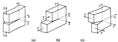 | Figure 1. (a) Mode I – aperture; (b) Mode II – sliding; (c) Mode III – tear |
The fracture mechanics approaches three important variables in its study, the applied stress, the fissures size (trine) and the tenacity to the fracture of the material. In that way, the study aims at the critical combination of those three variables[10]. According to Figure 1, there are three basic ways of the enlargement and growth of trines, presented in the fracture mechanics.The stress intensity factor (KI, II, III) defines the amplitude of the singularity stresses in the tip of the trine and it is related with the geometry structure features and with the applied stresses. KI, II, III is a value that is related with the geometric features of the structure, a way of loading and also of applied stress on the same, being defined by the Lineal Elastic Fracture Mechanics(LEFM) through the Equation 1. In this calculus, σis the normal stress, a is the size of the trine and Y is a factor that depends on the way of loading and of the geometry of the structure.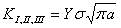 | (1) |
The critical stresses intensity factor in the first way of trine opening (KIC) is a mechanical property of the material (Figure 1). This value indicates a limit condition of propagation of fissures in mode I. In the analysis of problems of LEFM, that property has been adopted as a criterion of defect in structures and mechanical components.The standart ASTM E-399[8] establishes experimental procedures that should be adopted in the tests to validate the obtaining of KIC. A quite diffused test of fracture is the one with compact specimen (Figure 2).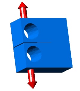 | Figure 2. Geometry of the compact specimen (ASTM E-399[8]) |
The thickness of specimens is related to the gradual transition of the state of equilibrium of stress for the state of equilibrium of strains[10]. To guarantee the existence of the stress state of equilibrium, ASTM E-399[8] it is established some connections between the mechanical and geometric properties of the material in order to guarantee the state of equilibrium of strains. If all those requirements for the validity of the test are followed, according to Equation 2, the value KQ found through the Equation 3 is related to an estimate of the tenacity to the fracture. In agreement with the Figure 2, in those equations a is the length of the trine, B is the thickness of the substance proof, W it is its length and σY is the limit of the material linking. | (2) |
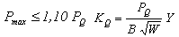 | (3) |
Another parameter used in Fracture mechanics is the integral J. This parameter it is related with the energy absorbed by the material, that includes a component due to the plastic strain and other elastic one. For materials that adapts to LEFM, the rate of liberated energy is equal to the absorbed energy, soon J = G. In this case, the integral J can be related with the stress intensity factor through Equation 4. The mathematical formulation of integral J can be expressed by Equation 5.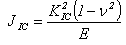 | (4) |
 | (5) |
According to Figure 3,  is the strain energy density,
  are the components of the tensile vector, nj are the components of the unitary vectorΓ, ui are components of the strain vector and ds is the incremental length along the pathΓ, E is the module of elasticity and ν the Poisson coefficient.
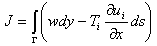
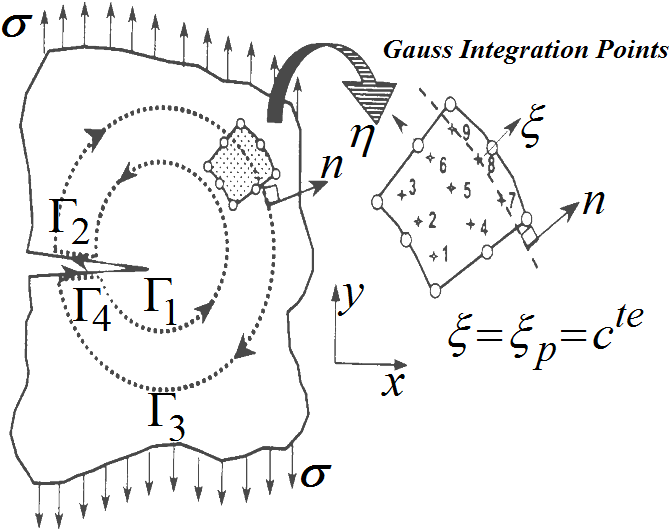 | Figure 3. Numerical integration path to evaluate the J integral (Oller[2]) |
The formulation described by Equation 5 is not usual for analysis through finite elements due to the numeric difficulties for the definition of the integration in only one way. According to Oller[2] and Dias[11], the integral is defined by the waysΓ1, Γ2, Γ3 e Γ4, according to Figure 3.
3. Methodology
The simulations were accomplished in a sample of tungsten carbide with 6% of Cobalt (WC-6Co), whose properties are presented in the Table 1. This hard metal presents a fragile mechanical behaviour performance when submitted to tensile efforts, and elastoplastic behaviour under compression. Due to mechanical peculiarities, this material is difficult to analyse from the conventional mechanical tests, mainly due to its high superficial hardness, making it difficult the preparation of the proofsubstances[11]. Other way to determine the mechanical characteristics has been through tests that are not very conventional as, for instance, the Vickers test[9]. In both cases, the numeric analysis can come as a good alternative to evaluate the tenacity fracture of this material.| Table 1. Mechanical properties of WC-6Co[11, 12] |
| | E (GPa) | ν | H (GPa) | σy (MPa) | KIC (MPa·m1/2) | JIC (Pa·m) | | 630 | 0,28 | 18,0 | 5760 | 10 | 146,29 |
|
|
Table 1, H is the Vickers hardness and JIC was obtained through Equation 4, that relates KIC with to the elastic component of integral J.In the first stage, the analysis took place through a model using isoperimetric plane elements with eight nodes. To reduce the computer effort, it took advantage of the symmetry of the problem and it was just represented its half result, according to illustrated mesh in picture 4a. The applied nodal loading was obtained through the Equation 3. In this stage, different mesh configurations were tested, aiming at reducing the number of elements without having problems with the numeric results, being careful to represent the singularity around the tip of the trine[7].In a second stage, from the bidimensional mesh that has used the lowest number of elements to interfere in the global results, different tridimensional meshes were also generated capable to represent this test with compact substances proof (Figure 4b). In this stage isoperimetric solid elements were used with 20 knots. Again, the representation of the singularity in the tip of the trine was a careful procedure, being properly described. Different meshes were tested with, respectively, three hundred, six hundred and thousand and two hundred elements.To guarantee a better numeric control of these tridimensional models, was chosen to apply the load in the substance proof through its prescribed displacement, in other words, a nodal displacement corresponding to the loading result of the value of the Equation 3 was applied for the geometry of the specimen. | Figure 4. (a) Bidimensional model of the specimen; (b) Tridimensional model |
In the last stage, was chosen to represent numerically the Vickers indentation test through tridimensional numeric models. In 1983, Niihara[13], based on an experimental analysis of the performance of the elastic-plastic field of stress surgeries in the area of the indentation together with the beginnings of the of the Lineal Elastic Fracture Mechanics, presented an expression to evaluate the WC-Co tenacity of the starting from the radial superficial trines that appear in these test, as represented in Figure 5.The Vickers test presents a very important particularity from the point of view of the numeric simulation, as the value of the superficial hardness doesn´t depend on the applied load, this way it can be considered as proportional the reason between the force and the area of impression of the indenter. Therefore, it was possible to do the numeric analysis of the application of the load of the rigid indenter in the sample test through its prescribed displacement, allowing a better numeric control during the indentation cycle.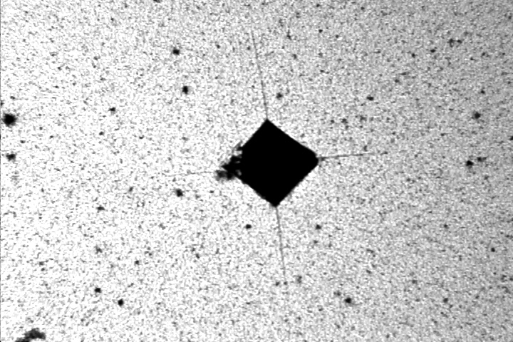 | Figure 5. Radial and surface cracks in WC-6Co (Dias et al.[1]) |
Using the concepts of the fracture mechanics, it was possible to establish a condition capable to identify the collapse of elements or the knots during the propagation of the trines in the indentation test. This condition would be determined through the critical stress intensity factor of WC-6Co. This way, the resolution of the fracture problem through FEM would consist on the resolution of successive lineal problems, however different from each other[1, 2]. At the end of each stage, the values of the stress intensity factor (KI) for different front points of the trine could be compared with the critical stress intensity factor (KIC) of the material, establishing the instant of the growth of the trine.
4. Results and Discussions
4.1. Bidimensional Models
The numeric results of tenacity to the fracture were compared with the experimental value found in the literature. Table 2 presents the meshes with different numbers of elements, the respective applied loads, the geometric parameters of the specimen and the numeric results obtained for integral J. The meshes are described by the number of elements of the complete model and for the number of elements used on the tip of the trine.The first and second meshes present a similar plenty configuration in the tip of the trine. The difference of these meshes is the geometric parameters, in other words, the size of the specimen modelled. In the third mesh, was chosen for less refined distortions in the model. A ruder mesh in the distant area of the trine proved not to influence the values obtained for the field of stress and strains in the singular area, as well as in the value of tenacity to its fractures[7, 14]. In the other side, the reduction of the number of elements in the tip of the trine propitiated elements less distorted in this area. In the last meshes, the distortions were varied obtaining a mesh with the smallest number of elements, without committing the numeric results for JIC, being of 146,29 Pa·m for the WC-6Co studied.| Table 2. Comparison between the numerical results of JIC integral for different meshes |
| | | | Elements | Dimensions of CT | | | | Load (kN) | model | trine | W (m) | B, a (m) | JIC(Pa·m) | | Mesh 01 | 1464,0 | 427 | 12 | 2 | 1 | 144,18 | | Mesh 02 | 66,26 | 411 | 12 | 0,254 | 0,127 | 144,74 | | Mesh 03 | 66,26 | 112 | 8 | 0,254 | 0,127 | 144,83 | | Mesh 04 | 66,26 | 104 | 8 | 0,254 | 0,127 | 144,69 | | Mesh 05 | 66,26 | 94 | 8 | 0,254 | 0,127 | 144,42 | | Mesh 06 | 66,26 | 60 | 6 | 0,254 | 0,127 | 144,12 |
|
|
4.2. Tridimensional Models
From the studies done in the elaboration of the meshes for the bidimensional, we got to the mesh of number six, which possesses a total of sixty elements, presenting a difference of 1,5% in the evaluation of JIC. In this case, the nodal displacement was of 1,52·10-5m in the point of application of the tensile load. To reduce the computational work we adapted this mesh to represent the tridimensional model. We opted to apply the loading through the displacement prescribed in the line of application of the load, instead of calculating the loading in each knot along the thickness of the model through the function of interpolation of the used element.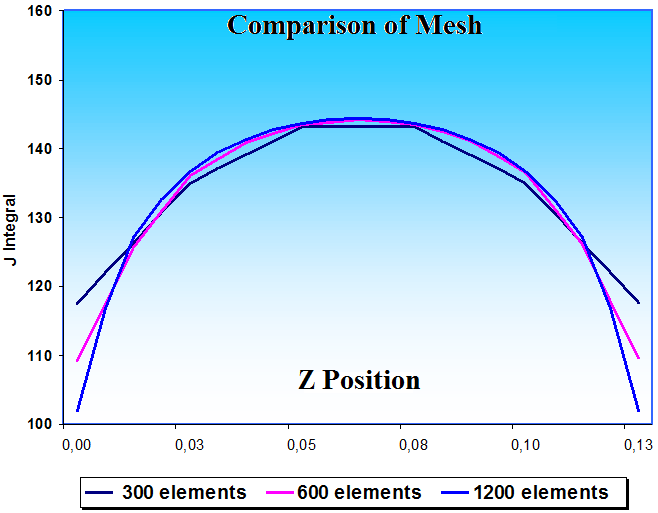 | Figure 6. Numerical distribution of the J integral along the thickness of the specimen |
Figure 6 shows the numeric distribution of the values of integral J in the direction of the thickness of the specimen. Three different meshes were used, with three hundred, six hundred and thousand and two hundred elements. The numeric results obtained were very similar and they present a discrepancy in the close areas to the free surfaces from the specimen. This can be explained by the fact that the stress in z direction (thickness) is null in the free surfaces. This constitutes a plan of stress, while in the central area the prevalence of a plan state of strains.According to Courtney[15], this performance induces different fracture mechanisms and, consequently, different factors of stress intensity. In that way, the KI values tend to be larger in the central area than in the extremities of the structure in analysis. Besides, in that area it was obtained closer values of the JIC of the material, since the value for this property is obtained by the standart ASTM AND-399[8] in this type of plan state of strains. The distribution of the normal stress calculated in the tridimensional model of the test is illustrated in isometric view by the Figure 7.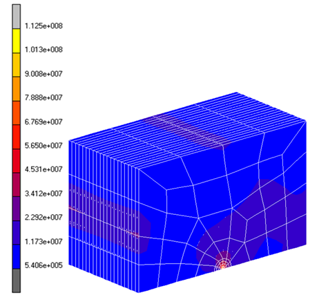 | Figure 7. Stress distribution of tridimensional model (Pa) |
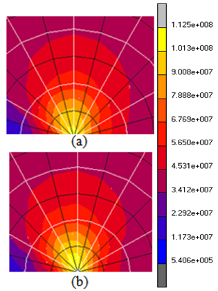 | Figure 8. Equivalent von-Mises stress distribution in tridimensional model - detail of the crack tip: (a) Lateral surface of the specimen; (b) Central face |
We cut twice to see the stress distribution in different plans in the model. The first plan studied was the view of the lateral surface, being the other obtained by a parallel cut to the surface that goes by the center of the specimen. The analysed plans are respectively showed in Figure 8a and 8b.Due to the appearance of a σZZ stress component, the central region of the specimen becomes characterized by a triaxial stress state. Figure 9 illustrates the field distribution of von-Mises stresses at the front crack.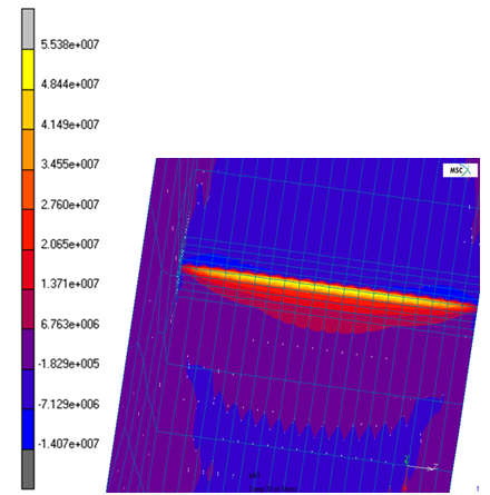 | Figure 9. σZZ normal stresses along the front of the crack in tridimensional model |
4.3. Proposal for Tridimensional Model of the Vickers test with the Merger Cracks
Figure 10 shows the proposal of a tridimensional model for the indentation test that incorporates a semicircular trine in the direction of the diagonal of the indenter in the plan III of the illustration. The trine was positioned in the radial direction of the diagonal of the indenter and it is in agreement with the experimental and numeric results found in the literature for WC-6Co[9, 14]. This geometry is also shown consistent with the geometry of the Palmqvist radial trine formed during the indentation test (Figure 5).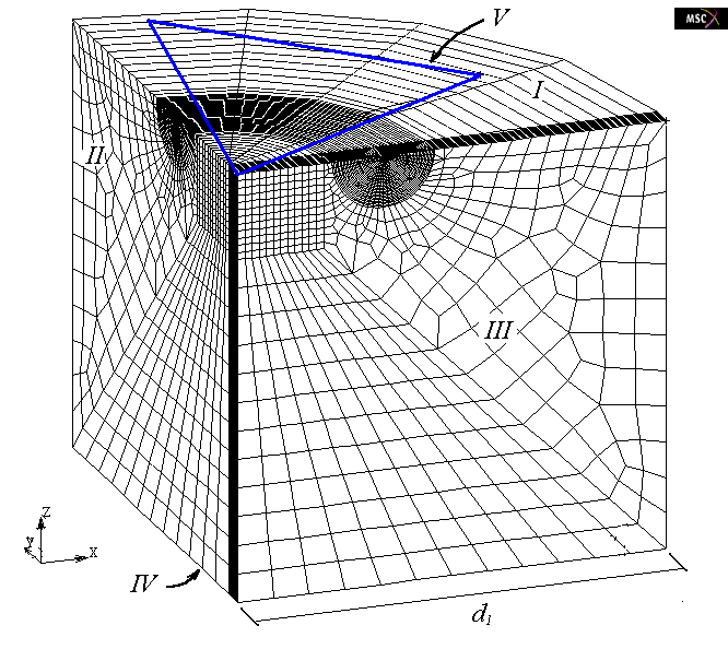 | Figure 10. Model of indentation test incorporating a radial semicircular surface crack |
5. Conclusions
The use of different meshes allowed a reduction in the number of used elements keeping the accuracy in the numeric results for JIC. This reduction of elements brings in a computing return, mainly in analyses with tridimensional models. The distant area from the trine doesn't have large influences about the stress intensity factor, soon the use of a ruder mesh in this area was also of great importance to reduce the number of element used. Finally, the use of many elements in the tip area of the trine can create distorted elements, and harm the obtained results. It should be reminded that the formulation of integral J makes it possible an evaluation of the parameter wanted with reasonable accuracy, even in ruder meshes.In the tridimensional tests it was verified that the gradual transition of the stress plan state (in the extremities) for a triaxial state of stresses was accompanied with the appearance of a gradient of σZZ in front of the trine. The increase of that component as when it goes forward in direction to the center of the specimen provokes the increase of the equivalent von-Mises stresses. The triaxiality of the central part reduces the size of the area of plastic-strain, avoiding an increase of numeric KI of the structure.In a continuation of this work, it intends to implement a methodology to simulate the growth of a radial trine in the indentation test through the increment of its size in the points or nodes, being initiated when the value of the stress intensity factor reaches the critic (KI>KIC), being disconnected the nodes of the adjacent elements, increasing the trine and beginning a new analysis. The resolution of successive analyses could indicate the final form of the trine during the indentation cycle.
References
| [1] | A. M. S. Dias, P. F. B. Sotani, G. C. Godoy. “Simulação do Ensaio de Indentação em Filmes Finos com o Uso de Modelos de Trinca Difusa”, Revista Matéria, 15, n. 3, pp. 422-430. 2010. |
| [2] | Oller, Sérgio. “FracturaMecánica. Um Enfoque Global”, 1a Ed, Publicado por: CIMNE (Centro Internacional de Métodos Numéricos EnIngeniería), Barcelona, 286 p. 2001. |
| [3] | P. Soltani, M. Keikhosravi, R.H. Oskouei, C. Soutis, “Studying the tensile behaviour of GLARE laminates: a finite element modelling approach”. Applied Composite Materials, 18 (4), pp. 271–282, 2010. |
| [4] | E. Barbieri, M. Meo, “A meshless cohesive segments method for crack initiation and propagation in composites”. Applied Composite Materials, 18 (1), pp. 45–53, 2011. |
| [5] | Karthik, V., Laha, K., Parameswaran, P., Kasiviswanathan, K., Raj, B., “Small Specimen Test Techniques for Estimating the Tensile Property Degradation of Mod 9Cr-1Mo Steel on Thermal Aging,” J. Test. Eval.,Vol. 35, No. 4, pp. 438 – 448, 2007 |
| [6] | Partheepan, G., Sehgal, D. K., and Pandey, R. K., “Finite Element Application to Estimate In-Service Material Properties Using Miniature Specimen,” Int. J. Mechan., Indust. Aerosp.Eng., Vol. 2, No. 2, pp. 130–136.0002-7820, 2008. |
| [7] | E. E. Medeiros, A. M. S., Dias. “Análise de Ensaios de Fratura Através do Método dos Elementos Finitos”, Anais do VII Simpósio de Mecânica Computacional. Araxá(MG) – Brasil. 2006. |
| [8] | ASTM (American Society for Testing and Materials), “E399 - Standard Test Method for Plane-Strain Fracture Toughness of Metallic Materials”, pp. 512-532, 1990. |
| [9] | A. M. S. Dias. Modenesi, P.J., Cristina, G.C., “Computer Simulation of Stress Distribution During Vickers Hardness Testing of WC-6Co”, Materials Research, v. 9, n. 1, pp. 73-76, 2006. |
| [10] | Anderson, T. L. “Fracture mechanics - Fundamentals and Applications”, 2nd Ed, CRC Press Inc., Boca Raton, Florida, USA, 688p. 1995. |
| [11] | A. M. S. Dias. “Análise Numérica do Processo de Fratura no Ensaio de Indentação Vickers em uma Liga de Carboneto de Tungstênio com Cobalto”, Tese de Doutorado. Universidade Federal de Minas Gerais, Belo Horizonte, Brasil, 200p. 2004. |
| [12] | E. M. Trent. “Metal Cutting”, 2nd Ed., Butterworths& Co. Press, London, England, 245p. 1984. |
| [13] | K. Niihara.“AFracture mechanics Analysis of Indentation Induced Palmqvist Crack in Ceramics”, J. Materials Science Letters, 2, pp.221-223. 1983. |
| [14] | N. C. Santos, J., Carvalho. “Computational Methods for the Determination of Stress Intensity Factors”, In: Proceedings of XVI International Congress on Mechanical Engineering, Uberlândia – MG, Brasil.[CD-ROM]. 2001. |
| [15] | T. H. Courtney, “Mechanical Behavior of Materials”, 1st Ed, McGraw Hill, New York, pp. 441. 1990 |
 Abstract
 Reference
 Full-Text PDF
 Full-Text HTML