Y. Yanawati , I. Daut , S. Nor Shafiqin , I. Pungut , M. N. Syatirah , N. Gomesh , A. R. Siti Rafidah , N. Haidar
Center of Excellence for Renewable Energy (CERE), School of Electrical Systems Engineering, Universiti Malaysia Perlis (UniMAP)
Correspondence to: Y. Yanawati , Center of Excellence for Renewable Energy (CERE), School of Electrical Systems Engineering, Universiti Malaysia Perlis (UniMAP).
| Email: |  |
Copyright © 2012 Scientific & Academic Publishing. All Rights Reserved.
Abstract
Decreases of rotor steel laminations thicknesses will decrease the total loss and increases an induction motor efficiency. In this paper, two models of a three phase induction motor with different thickness of rotor steel laminations, 0.35 mm and 0.50 mm, have been thoroughly investigated and analyzed in term of efficiency, power factor and loss field. The comparison is done by using FEM software simulation and hardware experiments. Based on the results, it shows that the motor with 0.35 mm steel lamination rotor is more efficient compared to the 0.50 mm steel lamination rotor.
Keywords:
Efficiency, Losses, Loss Fields, Induction Motor, FEM
1. Introduction
Induction motors are widely used for various industrial applications. In the past, approximate methods have sufficed. However, at the present time, there is a greater need to build more efficient machines and to utilize material more economically. Their design parameters are evaluated from the formulae based on the approximations to actual flux distribution in the machine cross section. In recent years, the finite element method has become a very popular and practical tool for computing magnetic fields in electrical apparatus[1].The induction motor was invented by Nikola Tesla in 1888. Induction motors can be used effectively in all motor application, except where very high torque or very fine adjustable speed control is required. Induction machines represent a class of rotating apparatus that includes induction motors, induction generators, induction frequency converters, induction phase converters and electromagnetic slip couplings[2].A rotating magnetic field, produced by a stationary winding (called the stator), induces an alternating emf and current in the rotor. It requires electrical connections to the rotating member; the transfer of energy from the stationary member to the rotating member is by means of electromagnetic induction. They are more rugged, require less maintenance, and are less expensive than direct-current motors of equal power and speed ratings. The resultant interaction of the induced rotor current with the rotating field of the stationary winding produces motor torque[3].There are two types of induction motor rotors which can be placed inside the stator. One is called a cage induction motor rotor, while the other is called a wound rotor. A cage induction motor rotor consists of a series of conducting bars laid into slots carved in the face of the rotor and shorted at either end by large shorting rings. This design is referred to as a cage induction motor rotor because the conductors. Wound-rotor induction motors are more expensive than cage induction motors and they require much more maintenance [4].By 1997, however, motor manufacturers will no longer be able to offer standard-efficiency motors. The Energy Act of 1992 defines new efficiency levels for several electrical devices including motors. It is assumed that as motors wear out, replacement motors will be the high-efficiency offerings. High-efficiency motors are built to reduce motor energy loss [5].The eddy currents are restrained by lamination. This skin will have emfs induced in it during magnetization reversals and the consequential ‘eddy currents ‘waste energy by dissipating heat. If the core metal is subdivided into thin sheets the balance of eddy current path resistance and induced emf shifts so that the overall power wastage in the core is radically reduced. The thinner the steel the more effectively eddy currents are restrained and the lower the core losses. The lamination pile of a given height contains less metal if made of 0.35mm steel rather than of 0.50mm steel due to the effect of the extra surfaces on the stacking factor[6].In this paper, the comparison of efficiency increment on 0.35 mm and 0.50 mm thicknesses of Non-oriented Steel Sheets for Induction Motor is presented.
2. FEM Modeling
Figure 1 shows the FEM software simulation by using the AC Analysis solver. The result is then arranged to Table 1 which is the nameplate data 0.5 Hp induction motor for both thicknesses non-oriented steel sheets. The input such as motor horse power, input voltage and frequency is inserted into the FEM software and the remaining result in Table 1 is the output from the FEM software.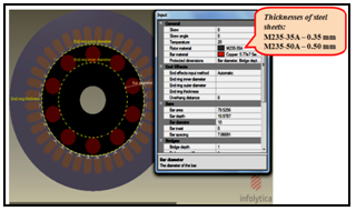 | Figure 1. The Designed FEM model of 0.5HP Induction Motor |
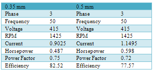
Table 1. 0.5Hp induction motor nameplate for both thicknesses
 |
| |
|
Figure 2 shows the design specification of the induction motor in millimeters for both thicknesses. The overall motor stator and rotor design is 55mm in radius. Based on Figure 2, it shows the round bar rotor slot type and the diameter of each slot that will be altered. The usage of this slot pattern is because it has a discrete ‘starting bar’ isolated from the main body of the conductor bar by a ‘leakage slot’, are applicable to motors with high conductivity material in the rotor cage. Besides that, this design of rotor bar has a higher locked rotor torque and a high slip[7].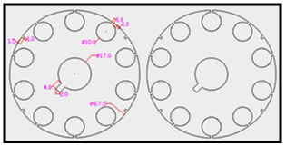 | Figure 2. AutoCAD Design of Rotor Bar with Slot Size Of 10mm |
3. Experimental Methods
Several experiment are conducted to evaluate the performance of the 0.5HP induction motor on 0.35 mm and 0.50 mm thicknesses non-oriented steel sheets in terms of losses, efficiency and power factor such as No Load Test, Blocked Rotor Test and DC Resistance Test.
3.1. No Load Test
The no-load test is to measure the stator copper loss, friction & windage loss and core loss of the induction motor. The idea of the no-load test after obtaining value such as input current, input power, power factor, line to line voltage, and rotor speed (rpm). Figure 3 shows the circuit for the no-load test of induction motor for both thicknesses. Based on the Figure 3, its shows two wattmeter, voltmeter, and three ammeters are connected to the induction motor. The motor is allowed to run without any mechanical load until the input readings to be stabilize. This can take from one hour up to four hours. When the motor is "warm-up" or stable, test results by adjusting the motor voltage and take a series of readings at 25%, 50%, 80%, and 100% of motor rated voltage to minimum voltage.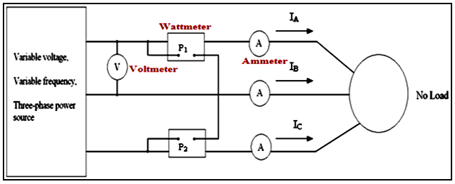 | Figure 3. No-Load Test Circuit of Induction Motor |
 | Figure 4. DC Resistance Test Circuit of Induction Motor |
 | Figure 5. Blocked Rotor Test Circuit of Induction Motor |
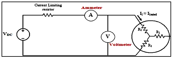
3.2. DC Resistance Test
The purpose of the DC Resistance test is to obtain the value of R1. Figure 4 shows the circuit for the DC resistance test of induction motor for both thicknesses. Based on the Figure 4, its shows current limiting resistor, voltmeter, and ammeter are connected to the induction motor. The DC voltage is applied to the stator windings. The DC source is adjusted to provide the current sheet is given the value of a stator and stator resistance between the two indicators that are determined from the reading of the ammeter and voltmeter. Because the current is DC, there is no voltage induced in the rotor and no resulting rotor current flow. To calculate the value of R1, below equation is used: | (1) |
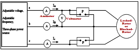
3.3. Blocked-Rotor Test
The blocked-rotor test is used to determine the value of X1 and X2. The generated voltage, current, and power are measure. The idea of the blocked-rotor test is to calculate X1 and X2 after obtaining value such as input current, input power, power factor, and line to line voltage. Figure 5 shows the circuit for the blocked-rotor test of induction motor for both thicknesses. Based on the Figure 5, its shows two wattmeter, voltmeter, and three ammeters are connected to the induction motor. The rotor is blocked to prevent rotation and balanced voltage applied to the stator terminals at a frequency of 25% of the rated frequency of the voltage at which the rated current is achieved.
4. Analysis Result and Discussion
This topic are discussed the result obtained from the FEM software simulation and hardware experimental.
4.1. FEM Software Simulation
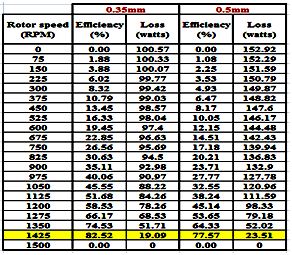
The induction motor design was analyzed by using Analysis and Performance Chart in order to obtain the characteristics such as eddy current loss, total loss, and efficiency. The results of AC analysis for 0.35 mm and 0.50 mm are shown in Table 2. Based on the result, several graphs are plotted such as Loss vs. speed and Efficiency vs. speed.Table 2. Data for Both Thicknesses from AC Analysis
 |
| |
|
Figure 6 shows the efficiency vs. Speed for both thicknesses non-oriented steel sheets for rotor frame (0.35mm & 0.50mm). This figure also illustrates how efficiency may vary with percent load. Generally, motor efficiency is relatively flat from rated load to 50% of rated load. Based on Figure 6, the graph shows that the value of efficiency for 0.35 mm is higher than 0.50 mm thickness, which is 82.52% and 77.57% respectively. The 0.35mm has an increment of 6% for the efficiency as compared to 0.50mm. It is because the lower losses can increase the efficiency of the induction motor.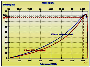 | Figure 6. Graph Efficiency vs. Speed for both thicknesses of steel sheets |
Based on the Table 2, Result shows that at the speed of 1425 rpm (highlighted in yellow) the losses for 0.35 mm thickness are 19.09 Watt where else for 0.5 mm it is 23.51 Watt as shown as Figure 7. This shows that the power loss for 0.35 mm is lower than the 0.50 mm thickness of non-oriented steel sheets. The 0.35 mm decreased of 18.8% for rotor loss compared to the 0.50 mm thicknesses of steel sheet. This is because 0.35 mm thickness has lower resistivity and lower the heat generated compared to the 0.50mm at that rpm.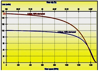 | Figure 7. Loss vs. Speed for both thicknesses of steel sheets |
The comparison of Loss fields between 0.35mm and 0.50mm thickness of non oriented electrical steel for rotor frame is shown in Figure 8.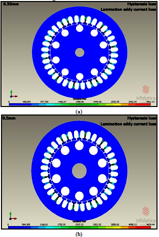 | Figure 8. Lamination Eddy Current Loss for Both Thicknesses Steel Sheets |
Based on Figure 8, it shows the difference of eddy current loss between the 0.35 mm and 0.50 mm thickness of rotor frame at 50 Hz. Both the figure shows that the eddy current loss for 0.35 mm thickness of rotor frame has less than 0.50 mm thickness based on the lamination eddy current loss. The value of eddy current loss for 0.35 mm is lower than 0.50mm thickness of steel sheet, which are 3.9 KWatt and 4.7 KWatt. The 0.35 mm has 19.52% lower eddy current loss than 0.50 mm thickness. The eddy current loss reduces with decreasing thickness of steel sheet. The magnetic core loss can also be reduced by using thinner lamination in the magnetic structure. This advantage makes rotor frame using 0.35 mm thickness of non oriented electrical steel (a) best choice for implementation in the induction motor.
4.2. Hardware: Experimental Test
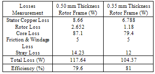
This topic discuss about the hardware experiment to further prove the simulation result that 0.35 mm thickness could increase the efficiency and lower the losses compared to 0.50 mm thickness of steel sheet. The experiments are No load test, Blocked rotor test and DC resistance test are performed.Table 3 summarizes the losses between two different thickness steel sheets which are 0.35 mm and 0.50 mm. Based on Table 3, it shows that 0.35 mm thickness rotor frame has indeed lower the losses compare to the 0.50 mm thickness rotor frame for the 0.5 HP induction motor. The 0.35 mm can reduce the losses by 13.27 Watt and increase the efficiency by 1.4% compared to the 0.50 mm thicknesses steel sheets. This shows that 0.35mm thickness with copper rotor bars can increase the efficiency and reduce the copper loss of the induction motor.Table 3. Loss Comparison for both thicknesses of steel sheets
 |
| |
|
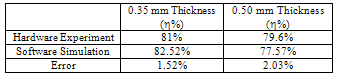
Table 4 shows the comparison between FEM software simulation and hardware experiment in terms of efficiency. It can prove the authenticity between the software simulation and hardware experiment. It also to justify the efficiency value obtains from the simulation analysis with error value approximately 2%. Table 4 also proves the theory that the thinner lamination steel sheet will produce high efficiency and reduce the total losses especially the copper loss and core losses.Table 4. Comparison Between Software Simulation and Hardware experiment
 |
| |
|
5. Conclusions
From the analysis, it shows that the 0.35 mm has an increment of 6% for the efficiency, a decrement of 18.8% for rotor loss and a decrement of 19.52% lamination eddy current loss as compared to that of 0.50 mm thicknesses steel sheet. High efficiency and power factor in induction motor can reduce harmonic and motor energy losses. Decrement lamination of steel sheet can reduce the eddy current loss. The magnetic core loss can also be reduced by using thinner lamination in the magnetic structure. Thus, rotor frame using 0.35 mm thickness of non-oriented steel sheets with 10mm slot rotor is the best choice for implementation in the induction motor.
ACKNOWLEDGMENTS
The authors wish to express appreciation to Lecturer, staff and friends of Center of Excellence for Renewable Energy (CERE) & School of Electrical System Engineering, UniMAP for their willing with this work and technical support.
References
| [1] | S.C. Tandon, Finite Element Analysis of Induction Machines, IEEE Transactions on Magnetics, Vol. Mag- 18, No. 6, November 1982. |
| [2] | Chapman, S. J. (Ed.). (2005). Electric Machinery Fundamentals (fourth ed.): Mc Graw Hill. |
| [3] | Akbaba, M., Taleb, M., & Rumeli, A. (1995). Improved estimation of induction machine parameters. Electric Power Systems Research, 34(1), 65-73. |
| [4] | Bottauscio, O., Chiampi, M., Concari, C., Tassoni, C., & Zucca, M. (2008). From the ideal to the real induction machine: Modelling approach and experimental validation. Journal of Magnetism and Magnetic Materials, 320(20), e901-e906. |
| [5] | PT Design (1997). Motors, Power transmission design, vol. A340. |
| [6] | Beckley P. (2002). Electrical Steels for rotating machines: IEE power and energy series; no.37. |
| [7] | I. Daut, Y. Yanawati, N. Gomesh, S. Nor Shafiqin, M. Abdullah, I. Pungut (2010). “Comparison of Torque between Different Diameters of Copper Rotor bar slot by Using FEM Software.” 2010 3rd International Conference on Computer and Electrical Engineering (ICCEE 2010), 16-18 November 2010, Chengdu, China. |
 Abstract
 Reference
 Full-Text PDF
 Full-Text HTML