-
Paper Information
- Next Paper
- Paper Submission
-
Journal Information
- About This Journal
- Editorial Board
- Current Issue
- Archive
- Author Guidelines
- Contact Us
International Journal of Materials Engineering
p-ISSN: 2166-5389 e-ISSN: 2166-5400
2011; 1(1): 1-16
doi: 10.5923/j.ijme.20110101.01
Review on Developments in Fiber Optical Sensors and Applications
 Abstract
 Reference
 Full-Text PDF
 Full-Text HTML
Venu Gopal Madhav Annamdas 1, 2
1School of Civil & Environmental Engineering, Nanyang Technological University, 639798, Singapore
2Laboratory of Monitoring Science, Online Research Platform, Hyderabad, 5000062, India
Correspondence to: Venu Gopal Madhav Annamdas , School of Civil & Environmental Engineering, Nanyang Technological University, 639798, Singapore.
| Email: |  |
Copyright © 2012 Scientific & Academic Publishing. All Rights Reserved.
The last couple of decades had witnessed a steep rise in extensive research of optoelectronic and fiber optical communication fields, which resulted in applications focused initially in military, aerospace equipments, and later in health monitoring for medicine, heritage culture and various engineering fields. Health monitoring has attracted the effort of many engineers throughout the world and is fast emerging as a pioneering field. It is helping to improve world economy in two ways; first, directly by providing longevity to all the important structures and secondly, by prevention of untimely failure leading to loss of life and money. This field is very vast, consisting of traditional monitoring methods as well as smart system based methods. The fiber optics belong to finest class of smart materials, there are many types and classifications of fiber optics based on necessity, manufacturer and the end user. This paper, gives a complete over view of fiber sensing systems and their usefulness. In addition, it highlights some of the general fiber optics available in the market with selected examples.
Keywords: Optical Fibers, Sensors, Structural Health Monitoring, Damage Identification, Engineering, Heritage Culture, Health Care
Cite this paper: Venu Gopal Madhav Annamdas , "Review on Developments in Fiber Optical Sensors and Applications", International Journal of Materials Engineering , Vol. 1 No. 1, 2011, pp. 1-16. doi: 10.5923/j.ijme.20110101.01.
Article Outline
1. Introduction
- The last couple of decades have witnessed a steep rise in extensive research of optoelectronic and fiber optical communication fields, which resulted in applications focused initially in military and aerospace equipments, and later in health monitoring for medicine[1,2], heritage culture[3] and various engineering fields[4-7]. The recent optoelectronics industry has brought products such as compact disc players, laser printers, bar code scanners and laser pointers. The fiber optic communication industry has brought more reliable telecommunication links with higher performance and decreasing bandwidth cost. Especially these developments in both optoelectronics and fiber optical communication industries were used extensively in fiber optic sensor (FOS) technology. FOS technology in-turn has often been driven by the development and subsequent mass production of components to support these industries[8,9]. Mutual developments have resulted in optimization of components and prices with development of high quality products to replace traditional sensors for rotation,acceleration, electric and magnetic field measurement, temperature, pressure, corrosion, crack formation, acoustics,vibration, linear and angular position, strain, humidity, viscosity, chemical measurements and a host of other sensor applications. In general, an effective and reliable monitor- ing system should be supported by high performance sensory technology which fulfill ‘A-to-E’ characteristics as follows, (A)ccuracy: sensor should have a reliable accuracy; (B)enefit: commercial price of the sensor should be in a reasonable cost; (C)ompact: sensor should be small in size, especially for embedded installation; (D)urable: serviceabi- lity of the sensor should be long-lived; and (E)asy: sensor should be easy to operate and time consumed for retrieving data should be close to real time measurement[10]. Thus the FOS technology aptly fulfills such characteristics, which uses optical fiber either as the sensing element ("intrinsic sensors"), or as a means of relaying signals from a remote sensor to the electronic devices that process the signals ("extrinsic sensors"). A report on FOS[11] shows a phen- omenal surge in United States market. It was valued at $235.0 million in the year 2007. This is expected to reach $430.0 million in 2009 and $1.6 billion in 2014, for a compound annual growth rate (CAGR) of 30.1%. Intrinsic sensors have the larger market share, worth $170.0 million in 2007 and an estimated $306.0 million in 2009. This is expected to reach $1.4 billion in 2014, for a CAGR of 35.2%. Extrinsic sensors generated $65.0 million in 2007 and an estimated $124.0 million in 2009. This segment is expected to reach $219.0 million in 2014 for a CAGR of 12.1%. Thus it is quite clear that the future of FOS industry is promising in USA. Even in countries like China or Russia and European Union, researchers are investigating and developing newer fibers, which are smaller than size of human hair. The overall market of FOS is quite large and it is expected to increase at a very steep growth rate.
2. Fiber Optical Sensors
2.1. Flow of Electrons and Photons in Wires and Fibers
- Photons are electrically neutral as they need not carry any charge. They do not have mass at rest, and their mass is negligible in motion as compared to the electrons. In a wire, electrons require a “push” (voltage) to overcome inertial and electromagnetic forces. Voltage generates flow of electrons (current) and in-turn generates heat in the wire. Moreover, the flow of electrons creates magnetic fields that extend beyond the boundaries of the wire. These fields may influence electrons traveling in nearby wires to create currents in them. These wires can also act as unwanted antennas, where electromagnetic radiation passing by the wire can stimulate a flow of electrons. These effects can create “crosstalk” between wires, leading to degradation of sensors. Additionally, these metal wires can attract lightning strikes causing failure to the equipments[12] or the sensors may themselves under go changes in presence of external factors. However, photons do not have any of these conditions associated with implementation of FOS systems. They do not create electric or magnetic fields even in the same fiber, thus effectively eliminating crosstalk. There is no interaction between two adjacent photons travelling in the same fiber unlike two adjacent electrons travelling in a single wire. Thus two wires or group of wires cannot be connected to single wire to avoid repulsion of electrons due to their common electric charge. Whereas, it is possible to combine an extra-ordinarily large number of signals onto a single fiber, such arrangement is known as multiplexing. Since no electrical signal is carried on the fiber, it is safer in harsh environments like presence of explosive gases or fuels. In some applications, weight and volume may not be critical but for many other applications, weight and volume can be extremely important, and minimizing these can be very critical[13,14].
2.2. Basic Fiber Composition
- Basically, a fiber is made of a glass or plastic that carries light throughout its length. Fiber sensors are sensitive to any parameter which can modify the intensity, frequency, polarization, or phase of light traveling through the fiber. The ability to interrogate numerous sensors multiplexed[15-18] along a single fiber permits an entire structure to be outfitted with sensors with a manageable number of leads routed to central access points. They facilitate transmission of light over longer distances and at higher bandwidths (data rates) than other forms of communications. Fibers are used instead of metal wires because signals travel along these fibers with less loss. The basic fiber structure needed to guide the light wave consisting of a core surrounded by a cladding as shown in Fig. 1(a). Moreover, the light ‘rays’ should remain within the fiber, which is possible only if the ‘index of refraction’ of the core is always greater than the cladding i.e the core and cladding indexes need not be constant but core index must be always greater. However, the fiber with constant core index is simple to fabricate and is usually known as step index fiber. Typical communicational-grade optical fiber sensors appear as long strands of glass material, with a core diameter of less than 100 microns. They usually have a core index of refraction between 1.450 - 1.480 radians. Plastic fibers with core diameters of 2 mm are usually utilized for certain short distance applications (< 500 meters). In absence of any cladding, the core can be “immersed in air”, which has an index of refraction of about 1.0 and the critical angle of incidence (greater the angle, effective is the fiber) would be close to the 41.8 degrees. Core and cladding diameters usually are specified together, for example, “85/125” refers to a fiber that has a core and cladding diameters as 85 and 125 microns, respectively. However, the latest fiber structure for use in National Aeronautics and Space Administration (NASA) is of a size of human hair. Core and cladding diameters of these sensors[19] are too small as compared to sizes of previous decade fiber structure.
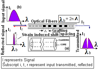 | Figure 1. FOS and FBG sensors (a) FOS fiber composition (b) principle of FBG |
2.3. Important Features of Fiber Sensors
- The FOS consists of a thin optical fiber, typically ranging from 75 microns to 125 microns in diameter, can be configured to measure a wide range of effects via changes in light beams that are propagating through the optical fibers. The important features are (1) Immunity to electromagnetic interference: protects from lightning strikes and electrical hazards (2) Rugged and robust: can withstand harsh environment and temperature either on or inside any composite. (3) Multiplex: many fiber sensors are inter connectable to result in extremely vast sensing network along a single fiber line. (4) Multifunctional capabilities: multiple parameters can be sensed along the same fiber line simultaneously, such as strain, pressure, corrosion, temp- erature etc[20]. (5) Optimized size: fiber sensors influ- ence neither the stiffness nor disturb the integrity of the host material. (6) Optimization of cost: a high degree of synergy with the telecommunication and optoelectronic markets can make the prospect of low cost, high performance devices very likely in the future communicational[12]. (7) Control Systems for effective structural health monitoring (SHM): deployment of fiber sensor arrays to assess the condition of a structure. For example: FOS system deployed (to measure strain, temperature or environment) at important locations on any structure. Moreover the FOS system can also be used not only to collect the data but also to respond to it. For example: a highway that senses an accident and acti- vates warning signs as a result of such deployment.
2.4. Fabrication and Types of Optical Fibers
- Optical-grade silica-glass is the predominant material for communicational[12] and sensing applications. The glass used for optic fiber is many times clearer than normal window. We could construct a pane of glass several kilometers thick and still match the clarity of a normal window. If water were this clear we would be able to see the bottom of the deepest parts of the ocean[21]. A fiber optic system using a glass fiber is certainly capable of carrying light over long distances. By converting an input signal into short flashes of light, the optic fiber is able to carry complex information over distances of more than a hundred kilometers without additional amplification. This is at least five times better than the distances attainable using the best copper coaxial cables. The system is basically very simple: a signal is used to vary, or modulate, the light output of a suitable source — usually a laser or an light emitting diode (LED). The flashes of light travel along the fiber and, at the far end, are converted to an electrical signal by means of a photo-electric cell. Silica-glass fibers are often doped with materials for instance Germanium dioxide and Aluminum dioxide to improve performance through changing the index of refraction and some other properties of the fiber. Hill et al[22] as the first to report photosensitivity in germa- nosilicate optical fibre and its application for fabrication of reflection filter. From there on, regularly never develop- ments evolved in fiber technology. We occasionally use plastic for optic fiber but its losses are still impossibly high for long distance communications but for short links of a few tens of meters it is satisfactory and simple to use. In the recent years[23,24], plastic fibers with performance suffic- ient for short distance communications or cold light illum- inating applications (typically less than 500 meters, and bandwidths less than 200 MHz) is increasing. It is finding increasing applications in hi-fi systems, and in automobile control circuitry. However plastic fibers are thicker than glass fibers by at least a millimeter, and can be handled without special tools or techniques. They were also signi- ficantly used due to their low cost and high fiber quality. For example, large-core plastic fibers (> 500 microns) can illuminate sufficient light without significant heat, for applications in car-dash instruments, equipment-inspection light sources, medical instrumentation and image applications[25] with no-electrical requirements. Irrespecti- ve of whether FOSs are silicon or plastic based, their applications are in telecommunications, ships, submarines, satellites, office buildings, trains, automobiles, manufactur- ing plants, scientific labs, trans-oceanic communications links, aerospace, oil and pipeline, civil infrastructures[6,17, 26,27], biomedical[28], healthcare systems[1,29] and every- where communication or data is exchanged[12][See later sections for details]. FOSs can be classified into four main categories based on intensity, phase, wavelength and polarization modulations[30,31]. However, these four categories can be treated as one category which is simply based on modulation or dem- odulation to measure shifts in amplitude, phase, frequency etc. Another classification is based on application type such as physical, chemical or biomedical sensors. Whether classification is based on modulation or application type, there organization either in the form of continuously dist- ributed systems or the quazi-distributed systems is describe- ed mostly. Usually, when a structure is large in size, it requires a large scale distributed FOS system to acquire a comprehensive monitoring of the structure; whereas if the structure is not large enough, effective monitoring can be achieved using quazi-distributed sensors[32]. There also exists another classification based on sensing capabilities such as intrinsic and extrinsic sensors[33] where these sensors are based on modulation or demodulation and these sensors could be physical or chemical or biomedical. These sensors can be organized into continuously distributed or quazi-distributed systems. Finally classification can also be based on the type of mountings (i.e., either surface bonding or embedded), where these sensors can be intrinsic or extrinsic. Thus, the classification is not universal but varies depending on type of sensing, mounting, distribution and type of application. Most of the current sensor designs are ‘wavelength or frequency modulations’ based such as fiber Bragg gratings (FBG) and ‘phase modulations’ based such as interferometric sensors[34,37]. Some sensor designs such as those based on intensity modulations have been developed and effectively employed in civil engineering applications[35]. The following sections will present some sensors typically useful for most of the engineering and medical applications. 1. Intensity modulated or distributed fiber sensorsIntensity modulated sensors are based on the modulation of light intensity (amplitude) in the fiber. This kind of sensor can measure any parameter that can cause intensity losses in the guided light beam. Sensors that vary the intensity of light are the simplest as only a source and detector are required. The advantages of these sensors are: simplicity of implementation, low cost, possibility of being multiplexed[38] and ability to perform as real distributed sensors. Fracture losses or local damages in a structure cause light intensity variations. Its main application is for fault finding and attenuation monitoring in optical networks. As these sensors can be distributed, they can be also suitable for the large structural applications, since all the segments of an optical fiber act as sensors, and therefore, the perturbations within various segments of the structure can be sensed. There exists two major distributed sensor methodologies, the first one is the optical time domain reflectometry (OTDR) and the next one is Brillouin scattering. In the OTDR, Rayleigh and Fresnel scatterings are used for sensing structural perturbations. It is not necessary to study about the scattering phenomena in detail as it works on simple light scattering principle. For example the OTDR relies on the reflection of light that has been launched into a fiber from an amplitude-modulated and pulsed source. Using the OTDR technique, from the backscattering of the light, it is possible to obtain the value of the light intensity along the whole fiber, by measuring the time of flight of the returned pulses. In this way, it is possible to detect losses in the fiber and to locate these losses with quite good spatial resolution. Distributed sensors have a great potential in civil engineering due to their inherent distributive nature[32], but they also possess certain limitations such as insufficient resolution, weak detectable signal and cumbersome demodulation system. Moreover as only relative variations in the intensity of the light source are measured and these variations lead to false readings, unless a referencing system is used[39].2. Spectrometric or quasi-distributed fiber sensorsThe spectrometric sensors monitor changes in the wavelength of the light. These sensors are not as sensitive as the interferometric sensors (see later section) but their configuration, installation, and data processing are extre- mely easy. An advantage of these sensors is that the sensed information (shift in wavelength) is an absolute parameter, and thus obtained absolute measurements are more reliable as compared to relative ones. The wavelength-encoded nature of the output also permits ease in multiplexing. How- ever, here intermittent segments of fiber act as sensors and such segmental formation is achieved by fiber gratings[22]. Intensive study on fiber gratings began after a controllable and effective method for their fabrication was devised by Meltz et al[40]. In recent years, there have been a number of research initiatives towards the development and deployment of FBG based sensors for sensing applications in civil and structural engineering[41-43,5]. A Bragg grating is a periodic structure, fabricated by exposing a photo-sensitised fiber to an ultraviolet light. Several gratings can be placed along a single optical fiber in an intermittent way to obtain a quasi-distributed sensing system. When light from a broad band source interacts with the grating, a single wavelength, known as the Bragg wavelength, is reflected back whereas the rest of the signal is transmitted. An external mechanical strain in the fiber (a stimulus) shifts the Bragg wavelength (response of the fiber) through expansion/contraction of the grating periodicity. Similarly, a temperature variation (stimulus) causes thermal expansion/contraction of the grating periodicity and also changes the refractive index (responses). These effects provide the means of employing the FBG written fibers as the sensor elements for measuring strains and temperatures (Fig. 1b;[44,40,45]. When light from a broad band source interacts with the grating, the Bragg wavelength is reflected back whereas the rest of the signal is transmitted. The Bragg wavelength
 depends both on the physical characteristics of the fiber and on the geometrical characteristics of the grating.
  is the effective refractive index of the mode propagating along the fiber and Λ is the period of the FBG. Both the effective refractive index and the grating period vary with changes in strain
  , a temperature change
  and a pressure change
  , imposed on the fiber. An applied strain and pressure will shift the Bragg wavelength through expansion or contraction of the grating periodicity and through the photo elastic effect.
 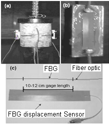 | Figure 2. Embedded and surface bonded FBG sensors (a) Embedded FBG in concrete specimen; (b) Surface bonded FBG on beam; (c) FBG fiber with protecting casing strip |
3. Some Selected Applications of Fiber Sensors
- The fiber sensors are used in past few decades and can be used in future in many fields, and their applications range from space to undersea. i.e every where were the light/data communication is feasible. 1) Transmission: In the chronological order, it is one of the first areas where optical fibers were used. The first theoretical prediction of practical applicability of optical fibers occurred in 1966, system experiments in 1976, and economically practical system deployments in 1980[77] . The “optical fiber or light wave communication” have the advantages of being accurate, descriptive and more readily understandable. In telecommunications, glass fibers that carried light wave communications were called “light guides”. In recent years it has become apparent that these light wave systems are steadily replacing copper wire as an appropriate means of communication signal transmission. The only basic difference is that the fiber-optics use light pulses to transmit information down fiber lines instead of using electronic pulses to transmit information down the copper lines. They span the long distances between local phone systems as well as providing the backbone for many network systems. These systems are also useful in cable television services, university campuses, office buildings, industrial plants, and electric utility companies. 2) Power Transformer hot-spot temperaturemeasuremen-t: Fiber-optic techniques were first used to measure winding temperatures in power transformers more than 30 years ago. Knowledge of the hot-spot temperature in a power transformer is a key element for its design and utilization. It enables manufacturers to refine their design, improve the quality and competitiveness, and users to utilize the full overload capacities of transformers and hence meet requirements of their customers without excessively reducing life expectancy of equipment[78-80]. The measurement of hot-spot to allow predictive loading and enhance capacity utilization has increased giving rise to more and more cost- effective fiber-optic temperature measurement systems such as the fluorescent decay time technique has been developed. These technologies offer an opportunity for direct hot-spot measurement without any detrimental effects to the dielectric integrity of the transformers. Additionally, the main source of power to industries or households or trains have to be monitored on real time basis, there safety especially during times of cyclone or earthquakes or tornadoes is crucial. Any physical problems in the transformers like dis-integraty, cracks in long range power transmission cables. Fractures in joints including direct buried cable, damages in cable tunnels, cracks in cable ducts or ancillary switchgear and other ancillary equipments can cause severe disruption (failure in power transmission network) to supply as well as reduce equipment lifetime. Additionally, if there is over head network (power cables), can result in sag or sudden short-circuiting. Thus, the fiber sensors for example like Sensornet’s Digital ‘Thermal Profiling’, ‘Condition Monitoring’, ‘Strain Profiling’ and Dynamic Cable Rating technology[81] offer a continuous snapshot of all these equipments for maximum efficiency and structural integrity. Moreover Sensornet provided a Sentinel DTS-XR Distributed Temperature Sensing system for monitoring the transmission network. The Sentinel DTS-XR provides world beating performance and can measure with high resolution at distances of 30km.3) Real time based complete monitoring of Aeroplanes/ spacecrafts: The term ‘complete’ refers to an integrated network of sensors, which could monitor not only structural elements, but also the health of electronics, hydraulics, avionics, and other systems in aeroplanes. All types of sensors like extrinsic, intrinsic distributed and quazi distributed sensors are adoptable for aerospace structures depending on need, parts of craft and type of monitoring. For example, Lee et al[82] demonstrated the applicability of FBG sensor system for wings quite effectively. Networks of sensors mounted on commercial aircraft might one day check continuously for the formation of structural defects, possibly reducing or eliminating scheduled aircraft inspections[83] like nerve endings in a human body, in-situ sensors offer levels of vigilance and sensitivity to problems that periodic checkups cannot[19,84]. Adoption of effective sensing system can greatly reduce maintenance expenses for commercial aircraft. Those costs are rising as the aircraft age, many well beyond their design lifetimes. Ground crew technicians might plug a laptop or diagnostic station into a central port on the aircraft to download structural health data. Eventually "these sensing systems" fitted with many sensors could self-diagnose and signal an operator when repairs are needed. The potential locations on aircraft where the fiber sensors can be placed and diversified monitoring parameters can make aerospace a very challenging field for adaptation of fiber sensors. For example the harsh environments in which these aerospace structures have to work are the major limit for the employment of standard fiber optic sensors for the ‘thermo-mechanical’ monitoring processes. Thermal loads which act on these structures do not allow the use of standard fiber optic sensors used for classic avionics application. In fact, many aerospace structures can be exposed to temperatures up to 1000°C, higher than the operation temperature of the standard fiber optic sensors. Latini et al[85] used a tunable laser source, to easily measure the spectral response of different fiber sensors intended to monitor thermal process. This allows performing a multi-sensor interrogation and analyzing many physical parameters, such as: temperature, strain, pressure, etc[20]. In particular they used temperature resistant Fiber Bragg Grating sensors; they were proved to be successful even up to 600°C. They have resulted in a good response in terms of: sensitivity, resolution, repeatability and dynamic range of the measurement were obtained. The NASA contractors and research collaborators in United States are aggressively working to develop newer sensors, and it was reported that the latest fiber structure for use in NASA is of a size of human hair. 4) Real time monitoring of ships: There are two factors here, the first one is the monitoring of ship movement in water/sea and the second one is the monitoring the ship itself for defects. In developed countries like United States, the authorized security (navy) uses fiber optics to secure ships in water. This includes logistical trail stretches back from the battle or disaster to supply bases in the U.S. Most of those supplies travel by sea on ships under the Military Sealift Command. During a war, more than 95 percent of all equipment and supplies is carried by sea going vessels and thus better access control and perimeter security needs to be provided. The technology includes fiber optic modules from Weed Instrument Co[86]. Even in other countries, the fiber sensors for ship monitoring are increasing, as US type models are adopted in several countries. For the second factor, i.e for monitoring defects in the ship, fiber sensor especially FBGs[87] are as apt as they are for any other engineering structures. Recently in 2001, embedded FBG technology was adopted for a Norwegian naval vessel by Wang et al for composite ship hull monitoring. Signal processing is key for real-time structure monitoring, and they have presented the modular signal processing system effectively. The other sensors which can be used are BOTDR strain sensors, as they have better efficiency due to good resolutions in signals[88]. They can be used for defect identification by measuring strains and also for detecting changes in water levels outside the ship. The future of FBG or BOTDR sensors are very promising for ships/vessels as it can help in prognosis of remaining life and save huge money for governments. 5) Real time monitoring of submarines and deep sea floor: The issues and solutions adopted for monitoring of ships can be used in as is conditions[88-89] even for monitoring submarines except that the FOS systems should have thorough water protection schemes. However, inorder to monitor deep sea floor[90], two factors, i.e, telemetry method and power supplying system, are important. There are two major technologies to understand real-time geophysical monitoring on a deep-sea floor. The tethered buoy-satellite system is one such technology. Even if a giant buoy system with strong moorings is used to maintain its reliability during extremely rough weather, it may be not strong enough. Other factors such as antenna direction heading to a stationary satellite, communication method between ocean floor and a surface buoy, and power sources for bottom equipment, are also difficult tasks to be overcome. During few decades, only a weather buoy, which took measurements at only the ocean surface, has been successful[91-92]. Another approach is to use submarine cable systems. The submarine cable system has long technological history and has been proven in the field[93]. Although optical fiber submarine cables are one of the most advanced and reliable technologies, the use of such submarine cables is extremely costly compared to free-fall-pop-up systems. Another kind of submarine cable is an analog coaxial cable, which still provides electrical power and real-time data-telemetry similar to optical fiber systems. If real-time measurement is mandatory for a particular observation such as likely for earthquake and tsunami monitoring, submarine cables would be the best choice. However, the fast growth in the field of fiber sensor will surely make them adoptable as the cost of these fibers is likely to reduce as advent of mass production. Someday, real-time geophysical observatories on a deep-sea floor could be realized with high reliability and at a reasonable cost.6) Real time monitoring of refinery process: Crude unit overhead line corrosion is one of the most serious problems in oil refineries[94]. Changes in process, environmental conditions, or feedstock that lead to HCl condensation are the main causes of overhead line corrosion. Corrosion is one of the major problems that affect the integrity of pipelines in refineries. All pipelines that transport petroleum products experience wall thinning and internal corrosion that are associated with the chlorides and sulfides in the products they carry. Buried pipes are often affected by external stress corrosion cracking due to the combined effects of the surrounding soil environment and pressure fluctuations. The procedure used to refine oil products requires careful attention to the temperature and pressure as well. In addition, by their very nature, refineries make use of inflammable materials that could be exposed to direct sunlight during the daytime. In order to ensure the safety of the plant, systems must be well-designed so that sparks cannot reach inflammables, and it is necessary to use rugged devices for the monitoring and management system. The control and monitoring system can comprise of effective fiber optic network as the communication network between key devices and the control center to also support voice, video monitoring, and security infrastructure[95]. 7) Real time monitoring of subsea, oil and gas industries: more or less the same factors discussed in monitoring refineries like corrosion, pressure and temperature[94-96] are vital, and the fibers like FBG[97] or BOTDR are apt even for monitoring of subsea. However, there are many more vital factors[96-98] like (a) Process conditions of oil and gas industries: Temperature, pressure, flow and composition. (b) Environmental conditions: Sea water temperature, pipeline spans, stress / strain at spans and landslide areas. (c) Required type of sensors: Pressure, temperature, strain gauges. (d) Sea water: composition / flow. (e) Location of sensors: Low spots, along pipeline at “selected” locations. (f) Dynamic simulation model of: Wells, subsea equipment and flow lines, multiphase pipelines, parts of the shore processing plant, real time model interfaced to vendor control system for online monitoring of slugs, tracking, offline planning / training simulator, etc. Once these factors are understood, then the aligning of fiber senors can be achieved for monitoring subsea, oil and gas industries. Additionally as presented by Brower and Prescott[98], a smart pipeline technology can be introduced for real-time monitoring. The smart pipeline technology allows for auto-adaptive measures to ensure trouble free operation of the entire pipeline system. Real-time monitoring and flow control issues drive the development of smart pipelines in oil & gas reservoirs for both onshore and offshore deepwater environments. A key feature of this technology is to develop full knowledge of flow assurance parameters in pipelines etc. A methodology to offer smart pipeline technology, including real time, on-line monitoring and control system for subsea production and pipelines was presented by Brower and Prescott[98]. The instrumentation was based on fiber optic technology. The system included problem prevention or mitigation with early detection and proactive intervention by applying new developments in the field of optic fiber monitoring. Such a system was deployed in deep water projects in the Gulf of Mexico. This had resulted in the development of a smart field control system, whose flow chart is as shown in Fig. 3 with automated data analysis and response. There are a number of operation and mechanical parameters which may be monitored or derived using this data system. The data acquired may be used to predict the onset of problems hence allowing timely corrective action. The measurement features of the new smart pipeline method included, real time data collection and modeling, dynamic and static strain measurement, vortex induced vibration, touchdown zone monitoring, stress concentrations, continuous or discrete temperature and pressure measurement along the entire system. Additionally, cryogenic temperature and structural monitoring in liquid natural gas (LNG), slug and anomalous flow, integration with smart well systems, integration with subsea processing, ultrasonic discrete measurement.
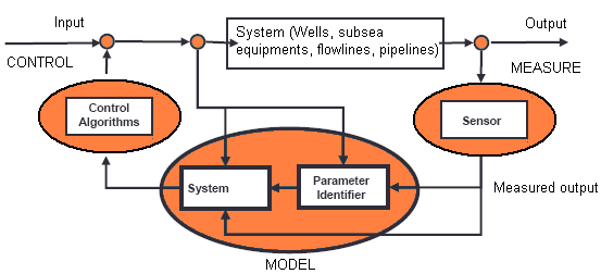 | Figure 3. flow chart of Fiber sensor application |
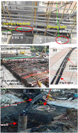 | Figure 4. Practical applications of FBG sensors (a) For bar dressing; (b) Monitoring temporary excavation support structures; (c) Pipe line fitted with fiber; (d) Monitoring pipe lines |
4. Protection of Fiber Sensors
- FOSs have to be surface bonded on or embedded in different host materials subjected to various conditions. Therefore, sensor interaction with host structure is of great importance especially if monitoring engineering structures or sub sea or construction. Effective sensing demands a compliant mechanical contact between the FOS and the host structure to ensure an appropriate transfer measurands of interest into light signals. However, an additional protection has to be used to isolate the delicate bare fiber from water and alkaline and from damages caused by the host structure. The protection scheme of the fibre in the sensing region differs with different host materials and type of bonding (i.e embedding or surface bonding). Experiences from recent applications showed that polymide coated fibers and epoxy were possible to secure an excellent mechanical coupling between the fibres and the anchorages in concrete structures[115]. In addition, the thermal expansion coefficient of the sensor packaging should be approximately equal to that of the host structure to avoid possible slippage between the interfaces. Moreover, the installation of FOS especially Bragg Gratings on base structures requires longitudinal uniform bonding. Otherwise, the non-uniform bonding of the gratings will cause several reflected Bragg wavelength peaks when the gratings are strained. In such a situation, accurate strain measurement will be impossible. It was observed that the survival rate of FOSs during installation was about 75-90%. Therefore redundant sensors should be used for critical measurements and careful planning is required. Especially, during installation, all-fibre compon- ents and connections should be delicately handled. Mechanical and thermal fatigue as well as chemical aggression will also decrease the life of FOSs. Special attention and various measures have to be taken to relieve these adverse effects on optical fiber health monitoring. Additionally for surface bonding FBGs, care has to be taken that the bonding layer employed between the FBGs and the host structure should be highly durable and does not peel off during the monitoring period.
5. Present and Future Generation Sensors
- Infrastructures, structures carrying liquids or gases, communicational systems, telephone lines, tornadoes or tsunami or cyclone warning systems etc are important facilities of modern day. Some of the natural calamities like Tsunami in South East Asia (2004) have raised the question of safety of ‘under sea or over sea communication lines’ or ‘oil industries’ or ‘marine life’. Some of the failures like space shuttle Columbia’s explosion on Feb 1, 2003 have raised questions of safety in aerospace/ space craft industry. Some of the civil engineering structures failures like Mississippi river bridge collapse on August 1, 2007 have raised concern about safety of civil structures. Thus health monitoring has attracted the effort of many engineers throughout the world and is fast emerging as a pioneering field. In the last couple of decades, abundant ‘types of fiber sensors’ are manufactured, re-manufactured with improved quality (year after year) and used for various fields[107, 116, Figure 5]. Thus the future of these fiber sensors is very promising, for example newer Brillouin FOSs have found its applications in many niche engineering and biomedical fields with better performance than fiber sensors of older genre sensors. These Brillouin sensors are effective even for long ranges (> 10 meters) and large areas to measure various parameters like temperature and strain along a single mode fiber[117] with high resolution quality either separately or simultaneously. The distributed Brillouin sensors can be used for much broader coverage (than FBGs) and can locate fault points not known prior to sensor installation. Unlike competing sensor technologies, Brillouin systems directly leverage the economies of scale from the millions of kilometers of fiber optic telecommunications fiber installed worldwide. There are two types of Brillouin sensors, first one is Brillouin Optical Time Domain Reflectometers (BOTDR) based Brillouin scattering of a single pulse. Second one is Brillouin Optical Time Domain Analysis (BOTDA), which uses a more complicated phenomenon known as Stimulated Brillouin Scatter (SBS). The BOTDA technique is significantly more powerful as it uses enhanced Brillouin scattering through two counter-propagating beams. The primary advantage of BOTDR technology is that only one end of the fiber needs to be accessible. Both these types of Brillouin fiber sensors were employed successfully due to their accuracy in measurement of various measurands like strain and temperature[118], for monitoring of various structures, components and parameters like pipeline buckling[119], pipeline corrosion[120], power transmission lines[121], crack detection by separate measurement of strain and temperature[122] and their simultaneous measurements[123].
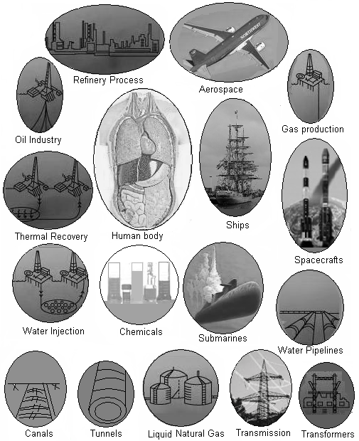 | Figure 5. Fiber sensor applications in various engineering fields |
6. Conclusions
- There are two important issues involved in health monitoring of any engineering structures or heritage culture or food or medicine. The first criterion is as a plausible replacement for conventional sensors to offer considerably improved reliability, performance, safety and optimized cost to the end user. The second is the development and deployment of FOSs in new market areas. The last two decades had resulted in optimization of components and prices with development of high quality sensors to replace traditional sensors for rotation, acceleration, electric and magnetic field measurement, temperature, pressure, corrosion, crack formation, acoustics, vibration, linear and angular position, strain, humidity, viscosity, chemical measurements and a host of other sensor applications. In summary, FOSs have been successfully applied to many fields such as gas and oil industry, and civil engineering structures, to monitor relative displacements, cracks, strain and temperature. Most of these applications as presented in this chapter utilize one or several of the significant advantages of Interferometer/ distributed/ quazi-distributed senors, for instance, their embeddability, ease of surface bonding, EMI immunity, and multiplexing ability, immunity to source intensity fluctuations (especially FBGs). These optical fibers are fragile and may be subjected to breakage during packaging and transportation, especially during installation under sea due to harsh water conditions. Hence depending on the nature of application, protection measures need to be taken. Wide applications of these sensors can be foreseen, not only in laboratory for proof of concept applications, but also in many practical situations as presented in this chapter like monitoring of bridges, pipelines, piles, traffic and excavation support structures.
ACKNOWLEDGEMENTS
- Author likes to thank Mrs Radhika Madhav Annamdas for her assistance in drafting. The author would like to thank members of Laboratory of Monitoring Science, which is a global research platform for smart material applications. The author likes to acknowledge all researchers whose work is cited in this paper. Further information of the work and its accuracy can be obtained from respective researchers/ authors of the cited articles.