-
Paper Information
- Next Paper
- Previous Paper
- Paper Submission
-
Journal Information
- About This Journal
- Editorial Board
- Current Issue
- Archive
- Author Guidelines
- Contact Us
International Journal of Materials and Chemistry
p-ISSN: 2166-5346 e-ISSN: 2166-5354
2025; 15(3): 54-58
doi:10.5923/j.ijmc.20251503.05
Received: Sep. 11, 2025; Accepted: Sep. 27, 2025; Published: Sep. 29, 2025

Morphology, Structure, and Electrical Conductivity of Cellulose–Polythiophene Composite: Hierarchical Organization and Synergistic Effects
 Abstract
 Reference
 Full-Text PDF
 Full-text HTML
Galia Zhunsalieva1, Nuritdin Kattaev2, Khamdam Akbarov2
1PhD Student, Department of Physical Chemistry, National University of Uzbekistan, Tashkent, Uzbekistan
2DSc, Professor, Department of Physical Chemistry, National University of Uzbekistan, Tashkent, Uzbekistan
Correspondence to: Galia Zhunsalieva, PhD Student, Department of Physical Chemistry, National University of Uzbekistan, Tashkent, Uzbekistan.
| Email: |  |
Copyright © 2025 The Author(s). Published by Scientific & Academic Publishing.
This work is licensed under the Creative Commons Attribution International License (CC BY).
http://creativecommons.org/licenses/by/4.0/

This work presents the results of a comprehensive study of a cellulose–polythiophene composite synthesized by oxidative polymerization of thiophene on the surface of a biopolymer matrix. Scanning electron microscopy revealed a sponge-like nanogranular structure of polythiophene with particle sizes of 10–100 nm and a developed porosity (~53%), as well as the fibrillar morphology of cellulose partially coated with the polymer (~21% of the surface). X-ray diffraction analysis demonstrated a hybrid amorphous–crystalline structure: low-angle diffuse maxima correspond to the cellulose matrix, while sharp peaks in the range of 37–65° 2θ are associated with crystalline domains of polythiophene with an average size of ~45 nm (calculated using the Scherrer equation). Thermogravimetric analysis confirmed the multistage character of thermal decomposition, with the composite exhibiting intermediate but improved thermal stability compared to pure cellulose. Current–voltage characteristics showed a linear and symmetric profile and an increase in specific conductivity by more than three orders of magnitude (from 2.4·10⁻¹¹ to 7.2·10⁻¹⁰ S/m) with increased polymerization time. It is established that the cellulose–polythiophene system possesses a hierarchical morphology and synergistic properties: mechanical flexibility and biocompatibility from cellulose, combined with the electrical conductivity and thermal stability of polythiophene. The composite is considered a promising material for applications in supercapacitors, sensors, membrane technologies, and flexible electronics.
Keywords: Cellulose, Polythiophene, Composite, Electrical conductivity, Nanostructure
Cite this paper: Galia Zhunsalieva, Nuritdin Kattaev, Khamdam Akbarov, Morphology, Structure, and Electrical Conductivity of Cellulose–Polythiophene Composite: Hierarchical Organization and Synergistic Effects, International Journal of Materials and Chemistry, Vol. 15 No. 3, 2025, pp. 54-58. doi: 10.5923/j.ijmc.20251503.05.
1. Introduction
- Modern trends in materials science are focused on the creation of functional composites that combine the properties of organic and inorganic components. Particular attention is paid to conducting polymers, which, due to the presence of π-conjugated systems, can ensure efficient charge transport and are applied in electrochemical devices, sensors, supercapacitors, and flexible electronics [1-3]. Among such materials, polythiophene and its derivatives (e.g., PEDOT) occupy a key position due to their high chemical stability, tunable conductivity, and compatibility with different matrices [4,5].At the same time, the use of biopolymers as matrices for conducting materials not only reduces cost and environmental impact but also imparts new functional characteristics. Cellulose is the most abundant natural polymer, combining mechanical strength, biocompatibility, and availability. Its fibrillar structure, developed surface, and the presence of hydroxyl groups create favorable conditions for the deposition and anchoring of conducting polymers [6-8].The development of cellulose–polythiophene composites offers great potential for new functional materials. Such composites combine the flexibility and biocompatibility of cellulose with the conductivity and electrochemical activity of polythiophene. However, the efficiency of these systems is largely determined by their morphology, degree of crystallinity, thermal stability, and the distribution of the conducting phase in the matrix. Therefore, the aim of this work was the synthesis and comprehensive investigation of the cellulose–polythiophene composite, focusing on morphology, structural characteristics, thermal stability, and electrical properties.
2. Materials and Methods
- Reagents.• Thiophene (C₄H₄S, analytical grade) – used as the monomer for polymerization.• Ferric chloride (FeCl₃, anhydrous) – used as the oxidizing agent for polythiophene and PT/S composites.• Dichloromethane (CH₂Cl₂, analytical grade) – the main solvent for thiophene polymerization.• Acetonitrile (CH₃CN, analytical grade) – used to dissolve FeCl₃.• Acetone (CH₃COCH₃, analytical grade) – used for washing the polymer and composites.• Distilled water – used for washing the samples.• Microcrystalline cellulose – served as the matrix for forming cellulose–polythiophene composites.All reagents were of analytical grade and used without further purification.Synthesis of Polythiophene (PT).Polythiophene was synthesized via the classical oxidative chemical polymerization method. Thiophene monomer (0.5 M) was dissolved in 100 mL of dichloromethane in a flat-bottom flask. Freshly prepared anhydrous FeCl₃ was dissolved in acetonitrile with vigorous stirring and added dropwise to the thiophene solution. The appearance of a dark-red, then black coloration indicated polymerization. The reaction proceeded under stirring for a fixed time. The resulting PT was filtered and repeatedly washed with acetone and acetonitrile until the filtrate became colorless, then dried in a vacuum oven at 60°C for 24 h.Synthesis of PT/S Composites.Composite films were obtained by oxidative polymerization of thiophene in the presence of cellulose. As an oxidizing agent, FeCl₃ was used [9]. Dichloromethane was selected as the optimal solvent. In a typical experiment, 0.8 mL of thiophene was dissolved in 25 mL of dichloromethane. To initiate polymerization, a suspension of the oxidizer (0.025 mol of FeCl₃ dissolved in 25 mL of acetonitrile) was added dropwise under stirring. Reaction mixtures were stirred at room temperature for 4, 14, and 24 h, yielding PT/S-4, PT/S-14, and PT/S-24 samples, respectively. The color change from red to dark brown confirmed polymerization. Unreacted thiophene and FeCl₃ residues were removed by ultrasonic treatment for 5 min, followed by drying at room temperature for 24 h.Characterization Methods.• SEM: Morphology and coating distribution were examined at ×500 and ×10,000 magnifications. Porosity and particle size distributions were analyzed using image processing.• XRD: X-ray diffraction patterns were recorded with Cu Kα radiation (λ = 1.5406 Å) in the 2θ range 5–70°, at 40 kV and 30 mA. Crystallite sizes were calculated using the Scherrer equation.• TGA/DTA: Thermal analysis was performed from 30 to 700°C at a heating rate of 10°C/min in air, recording mass losses and decomposition stages.• Electrical measurements (I–V): Current–voltage characteristics were measured up to 300 V. Specific conductivity was calculated using σ = G·L/A, where G is conductance, L is the film thickness (~30 μm), and A is the contact area (1 cm²).
3. Results and Discussion
- Morphology (SEM).SEM analysis revealed that pristine polythiophene (PT) exhibited a nanogranular sponge-like morphology with a highly porous architecture. At ×10,000 magnification (Fig. 1a), spherical and irregularly shaped grains ranging from 10 to 100 nm were observed (median ~21 nm, mean ~53 nm). The porous fraction accounted for ~53% of the surface, with pore sizes distributed from a few nanometers to several hundred nanometers (median ~19.5 nm). Such a combination of nanoscale particles and developed porosity results in a hierarchical structure that is advantageous for electrochemical processes, as it maximizes the accessible surface area and facilitates the penetration of electrolyte species. Additional image analysis confirmed a correlation length of ~0.15 μm and a fractal dimension of ~1.31, indicative of a network-like morphology capable of supporting percolative charge transport.In cellulose–polythiophene composites (Fig. 1b, ×500), the fibrillar structure of cellulose was partially coated by PT, covering ~21% of the surface. The porous fraction increased to ~78%, with pore sizes spanning submicron to tens of microns (median ~1.8 μm, mean ~12 μm). This coexistence of micro- and mesoporosity ensures both efficient electrolyte diffusion and strong interfacial contact between the conducting polymer and the cellulose substrate. FFT analysis showed a pronounced anisotropy with a dominant orientation at ~91°, coinciding with cellulose fiber alignment (anisotropy ratio ~5.45). The total groove length of ~6.3 mm in the field of view confirmed a well-developed relief providing additional “anchoring sites” for polymer adhesion [6–8].
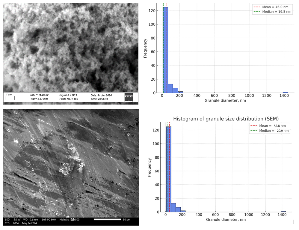 | Figure 1. SEM micrographs of particle size distribution of polythiophene (a) and cellulose-polythiophene composite (b) |
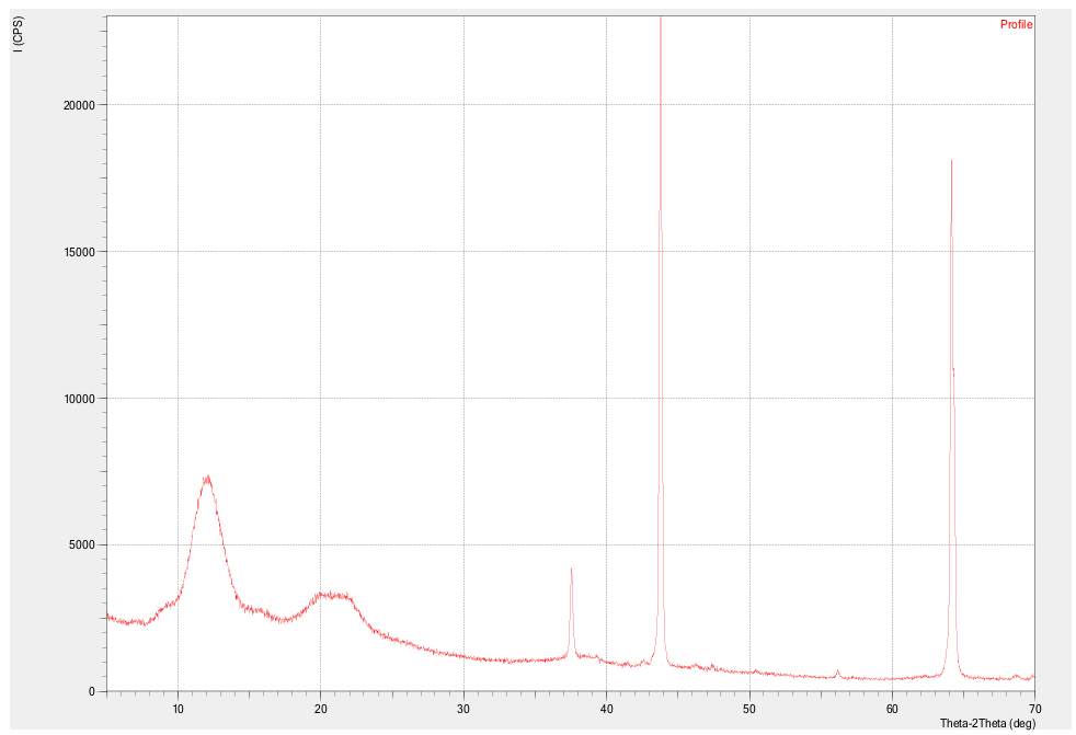 | Figure 2. X-ray diffraction pattern of cellulose-polythiophene composite |
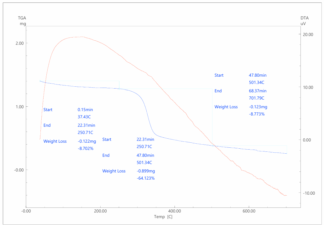 | Figure 3. Derivatogram of a cellulose-polythiophene composite |
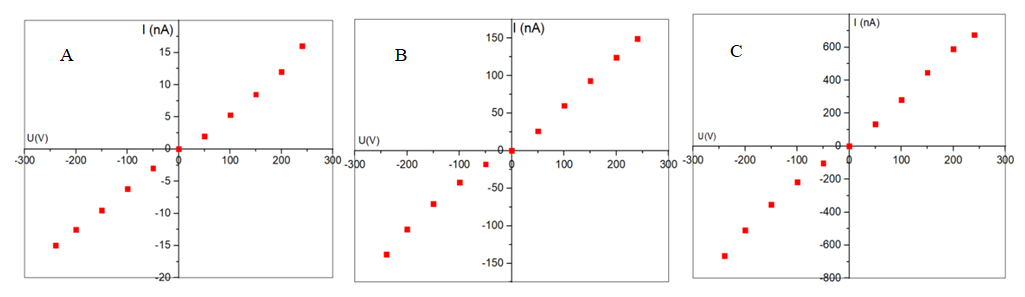 | Figure 4. Forward and reverse current-voltage characteristics of the cellulose-polythiophene composite at different (4 (A), 14 (B) and 24 (C) hours) times of thiophene polymerization |
4. Conclusions
- The cellulose–polythiophene composite exhibits a hierarchical morphology with nanoscale PT crystallites (~45 nm), macroscopic cellulose orientation, high porosity, and structural anisotropy. These features provide a balance of mechanical flexibility, thermal stability, and tunable conductivity, making the composite a promising material for supercapacitors, sensors, membrane technologies, and flexible electronics.