Atanda. P1, Adeniji. O1, Oluwole. O2
1Department of Materials Science and Engineering, Obafemi Awolowo University, Nigeria
2Department of Mechanical Engineering, University of Ibadan, Nigeria
Correspondence to: Oluwole. O, Department of Mechanical Engineering, University of Ibadan, Nigeria.
| Email: |  |
Copyright © 2012 Scientific & Academic Publishing. All Rights Reserved.
Abstract
This report presents a prelimnary investigation into the development of heat treatment refractory bricks using two local Nigerian clays. Ten different sample compositions of two different clay deposits from Awo (Egbedore local Government) and Ipetumodu (Ife North Local Government) areas of Osun State, Nigeria, were collected and analysed. The effect of Portland cement on the refractory properties of the clays was studied. The sample mixes of the clay and West African Portland Cement were prepared in varying proportions. Physical and thermal property tests such as thermal shock, thermal conductivity, apparent porosity, shrinkage and cold crushing strength were carried out on the samples. The prelimnary results obtained showed that the sample composition containing between 20% and 30% West African Portland Cement (WAPCO) of both samples can be used for the manufacture of heat treatment furnaces bricks by blending the addition with more non-linear expansivity materials to increase thermal shock resistance.
Keywords:
Heat Treatment, Refractory Bricks, Cement, Local Clays
Cite this paper:
Atanda. P, Adeniji. O, Oluwole. O, "Development of Heat Treatment Refractory Bricks Using Local Nigerian Clays", International Journal of Materials and Chemistry, Vol. 2 No. 5, 2012, pp. 185-191. doi: 10.5923/j.ijmc.20120205.01.
1. Introduction
Refractories are mineral and chemical-based materials with very high heat-resisting properties, which make them ideal for use in the construction of oven and furnace walls, ceilings, and associated elements of iron and steel industry blast furnaces, glass manufacturing tanks, cement kilns, hot stoves, ceramic kilns, open hearth furnaces, nonferrous metallurgical furnaces, and steam boilers[1]. Refractory materials can be made from clay refractory and non clay refractory. Non clay refractory are been made of alumina, zirconia, silicon carbide, chromia, magnesite, graphite and other less common materials, but the cost of these non-clay refractory is much higher than that of fire clay[2].Most clay refractory products are manufactured in the form of bricks, but refractory clay may also be formed into special shapes, such as the T-sections of refractory pipes or the small stands that support ceramic products during firing in a kiln[3]. Refractories have been an essential element in heat engineering plants since the 1960s, where they were successfully used to improve performance and energy efficiency. This is because refractories are chemically and physically stable at high temperatures. Depending on the operating environment, refractories need to be resistant to thermal shock and be chemically inert[4]. Good fireclay refractories should always have 24-26% plasticity and the Copyright © 2012 Scientific & Academic Publishing. All Rights Reservedshrinkage after firing should be within 6-8% maximum. A good fireclay refractory should also not contain more than 25% Fe2O3. Because of the abundant supply of fireclay and its comparative cheapness, the refractory bricks made out of it are the most common and extensively used in all places of heat generation[5].Fireclay bricks are used principally in furnace construction, to confine hot atmospheres and to thermally insulate structural members from excessive temperatures[4]. For fireclay brick, strength is not ordinarily an important consideration, because support of structural loads is usually not required. Some control is normally maintained over the dimensional accuracy and stability of the finished product.A group of refractory clays which can stand temperatures above Pyrometric Cone Equivalent (PCE) 19 are called fireclay. The clay which fuses below PCE 19 is not included under refractory. Fireclay is essentially of kaolinite group and has a composition similar to that of china-clay. In nature it is usually found to contain 24-32 per cent Al2O3, 50-60% SiO2 and LOI between 9 to 12%. Impurities like oxides of calcium, iron, titanium and magnesium and alkalies are invariably present, making it white, grey or black in colour[6]. Strictly speaking, fireclay is of sedimentary origin and mainly found in the coal measures, as bedded deposits[2].Refractory material is a material that is not deformed or damaged by high temperatures. The term high temperatures is somewhat vague but usually means above about 1000℃ (1830 °F) or temperatures at which, because of melting or oxidation, the common metals cannot be used. Refractory materials are usually non-metallic which are used to make crucibles, incinerators, insulation, and furnaces, particularly metallurgical furnaces. Therefore, a refractory is a material that will retain its shape, strength and chemical identity when subjected to high temperatures and is used in applications that require extreme resistance to heat, such as furnace linings[7].The oxides of aluminium (alumina), silicon (silica) and magnesium (magnesia) are the most important materials used in the manufacturing of refractories. Another oxide usually found in refractories is the oxide of calcium (lime). Fireclays are also widely used in the manufacture of refractories for high temperature heat furnace linings[8].There are two common forms of refractories, bricks and monolithics. Bricks (also known as fireclay bricks) are pre-sintered forms which can hold their shape. Monolithics are loose material which can be formed into complex shapes, or sprayed into place, and have to be sintered before use. Castable refractory cement is also commonly used[9]. Development of the above products can be produced from country’s vast natural resources (blessed with abundant clay deposit), which is important as far as the industrialization of a nation and saving foreign exchange is concerned. Currently a lot of industries in Nigeria import a lot of refractory related consumables on demand and specifications cannot be met locally. Based on the abundance of refractory brick raw materials in the country which can be deployed in the refractory industry, it is pertinent to develop and if possible to determine the viability of using locally sourced raw material in the country.
2. Experimental Procedure
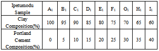
Table 1. Clay/Cement Mixtures using Ipetumodu Clay
 |
| |
|
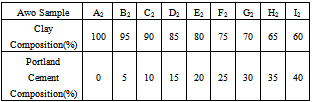
Table 2. Clay/Cement Mixtures for Awo Clay
 |
| |
|
The materials used during the course of the work were clay samples from Awo (Egbedore Local Government Area of Osun State) and Ipetumodu (Ife North Local Government area of Osun state)[10,11], both in Nigeria and Portland cement (from WAPCO Cement, Ewekoro, Ogun state, Nigeria)[12,13]. The clay samples used were obtained in lump forms, and were dried and grinded into powdery form. The samples were divided into ten equal parts of 1kg each in and labelled A1 to I1 for Ipetumodu samples and A2 to I2 for Awo samples (substrict 1 was used for Ipetumodu samples while substrict 2 was used for Awo samples). These ten different sample formations were obtained by varying the percentage of clay to Portland cement as shown in Tables 1 and 2. Each sample was hand rammed into rectangular metal mould to obtain the shape of the brick (fire clay) required. The moist samples were first allowed to dry at room temperature then sun dried and later furnace dried at a temperature of about 1000 ℃. The samples were subjected to standard refractory tests: thermal shock, thermal conductivity, shrinkage, apparent porosity, and cold crush strength tests.Thermal shock resistanceThe samples were gradually heated to a temperature of about 1000 ℃ in the furnace and soaked at this temperature for about 60 minutes. Samples were removed one after the other and dipped into non-flowing water at room temperature for about 60 seconds after which they were air-cooled for 5 minutes before being returned into the furnace at about 1000 ℃. Samples were soaked for 15 minutes before plunging into water again. This cycle was repeated with the samples inspected each for appearance of crack after each cycle. The cycle was repeated ten times, after which the bricks were assessed for appearance of cracks and degree of crack propagation.Thermal conductivityIt was determined by connecting two thermocouples to two different multi-meters and a hot plate. A hot plate supplied the necessary heat required and temperature readings were taken at both ends of the sample. The heat transfer equation (equation 1) was used to determine the conductivity of the brick. | (1) |
Where qx is the rate of heat flow (heat flux), A is the area of cross-section of the brick, x is the brick wall thickness, dt is the temperature difference across the brick wall and k is the thermal conductivity of the brick.Shrinkage propertyThe shrinkage of the samples was measured by determining the cross sectional area before and after sun drying and firing. It was determined using equation (2):  | .(2) |
Apparent porosityThis is the percentage change in volume of voids over the total volume of the sample. Weights of water-soaked samples and that of the oven-dried were taken. Equation 3 was used to estimate the apparent porosity. | (3) |
where W0: weight of the oven dried sample and W1: weight of sample soaked in water. The dried samples were weighed to obtain W0 and the later immersed in water for 24 hours to obtain W1. Cold crush strength testThe cold crushing strength of the samples was determined by using an InstronR cold crusher connected to a computer.
3. Results and Discussion
3.1. Results
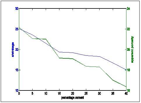
Figure 1 shows the shrinkage properties of the Ipetumodu and Awo clays compared with standard shrinkage property. It was observed that the shrinkage properties of both mixes were comparable with standard shrinkage at about 20-25% cement content and decreasing until 40% cement content. Too much shrinkage of refractories will lead to spalling.Figure 2 shows the thermal conductivity of both clay mixes. There is an increasing trend with increasing cement addition. High thermal conductivity will lead to lower refractoriness.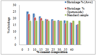 | Figure 1. Shrinkage properties of the two samples compared with the standard sample. |
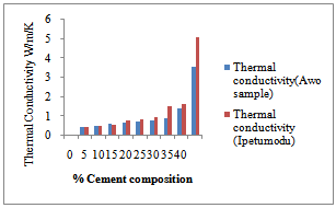 | Figure 2. Thermal Conductivities test result for the two samples |
Figure 3 shows the temperature difference between the two ends of the samples during the thermal conductivity test. It could be seen that the 100% had low thermal conductivities. This is corroborated in Figure 2 as noted earlier. Figure 4 shows the thermal cycling test for the clay mixes. As noted earlier in the shrinkage properties plot, it was also seen here that the mixes with high shrinkage properties were susceptible to thermal shock. Thus increasing cement content increased resistance to thermal shock and hence thermal spalling.Figure 5 shows the apparent porosity decreasing with increasing cement content while Figure 6 shows compressive strength increasing with increasing cement content.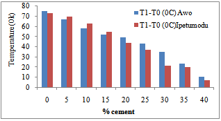 | Figure 3. Temperature-Cement composition test result of the two samples |
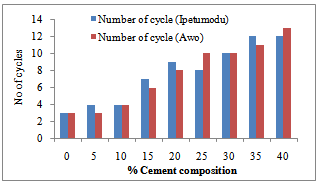 | Figure 4. Thermal shock strength resistance graph for the two samples |
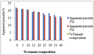 | Figure 5. Apparent porosity test result for the two samples |
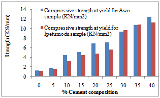 | Figure 6. Cold crushing strength test result of the two samples |
Figures7 to 16 show superimposed representative trend plots of important brick properties compared to each other in order to get a proper blend of properties from the bricks. Figure 7 shows superimposed thermal conductivity and cold crushing strength values for the two mixes. Figure 8 shows thermal conductivity and thermal shock values superimposed on each other.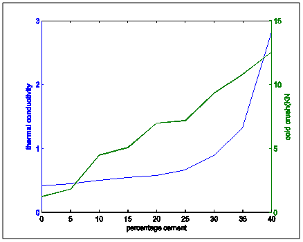 | Figure 7. Thermal conductivity and cold crushing strength properties variation with percentage cement composition |
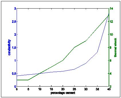 | Figure 8. Thermal conductivity and thermal shock properties variation with percentage cement composition |
Figure 9 shows apparent porosity and cold crushing strength superimposed on each other. It shows that as porosity is decreasing cold crushing strength increases. Figure 10 shows the superimposed plots of apparent porosity and no of cycles to thermal shock. This showed that as apparent porosity is decresing, resistance to thermal shock is increasing.Figure 11 presents the plots of apparent porosity and thermal conductivity. It showed that as porosity decreased, thermal conductiovity incresed.Figure 12 shows the suiperimposed plots of thermal shock and cold crushing strength. It showed that with increasing cold crusging strength, resistance to thermal shock increased.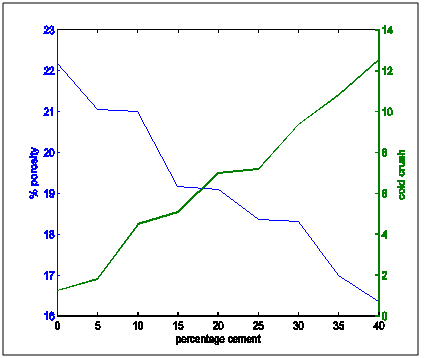 | Figure 9. apparent porosity and cold crushing strength variation with percentage cement composition |
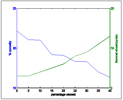 | Figure 10. Apparent porosity and thermal shock resistance properties variation with percentage cement composition |
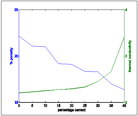 | Figure 11. Apparent porosity and thermal conduictivity properties variation with percentages cement composition |
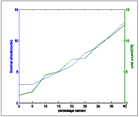 | Figure 12. Comparative plot of thermal shock resistance and cold crush strength variation with percentage cement composition |
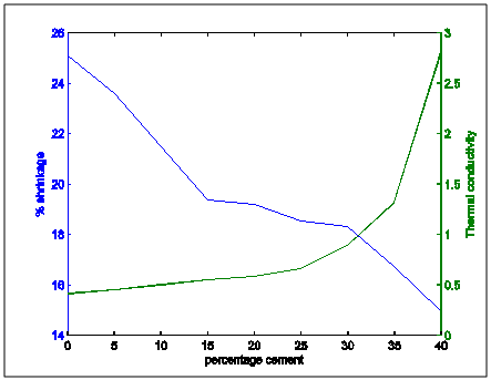 | Figure 13. Comparative plot of shrinkage and thermal conductivity variation with percentage cement composition |
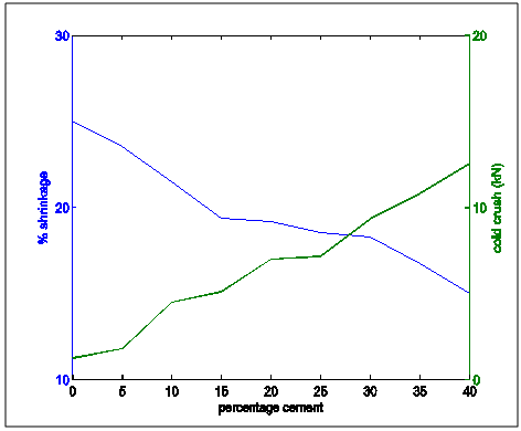 | Figure 14. Shrinkage and cold crush strength properties variation with percentage cement composition |
 | Figure 15. Comparative plot of shrinkage and Apparent porosity properties with increasing cement content |
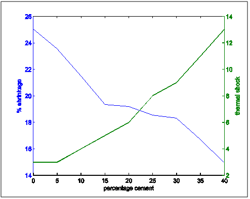 | Figure 16. Shrinkage and thermal shock resistance properties variation with increasing cement content |
Figure 13 shows the shrinkage and thermal conductivities superimposed on each other. It showed that as shrinkage decreased, thermal conductivity increased.Figure 14 shows shrinkage and cold crushing strength properties superimposed on each other. It showed that as shrinkage decreased, crushing strength increased.Figure 15 shows the shrinkage and porosity properties of the moulding sand with increasing cement content. It shows that the porosity decreased with decreasing shrinkage.Figure 16 shows the shrinkage and thermal shock resistance properties variation with Increasing cement content. It shows that as shrinkage decreased, thermal shock resistance increased. This is also known as resistance to thermal spalling.
3.2. Discussion of Results
From the the following facts could be deduced:Apparent Porosity Vs Shrinkage propertyAs the percentage cement composition of the sample increased the porosity of the sample decreased. This can be adduced to the total volume of the pores in the sample being closed up by the binding action of the increasing cement content which caused more compaction. It was also seen that as porosity decreased, shrinkage decreased. The superimposed curves (Fig.15) show samples containing 20-30% cement falling about a good range for shrinkage comparable with the standard in Fig.1. Low shrinkage is ideal for use in heat treatment furnace.Apparent Porosity Vs Thermal ConductivityFig.11 shows decreasing thermal conductivity as porosity increases. As porosity increases, a refractory material is less resistant to the eroding action of penetrants. Also, the air pockets reduce thermal conductivity. On the other hand, refractory materials should have low thermal conductivities. If we strike a balance between these two properties following up from the porosity-shrinkage plot we would be able to see a good trend in samples containing 20-25% cement composition.Apparent porosity Vs Thermal shockAs porosity increased, thermal shock decreased (Fig.10), following the same trend in the porosity-thermal conductivity plot. We could see the plots crossing about the 20-25% cement content. A refractory brick should not spall under rapid temperature changes. Apparent porosity Vs Cold Crush strengthThe porosity- cold crushing strength plot (Fig.9) followed the same trend as the porosity-thermal shock plot. If we interpolate the porosity percentage we obtained from the porosity-shrinkage plot we could see cement contents of 20-25% being quite acceptable. The cold-crush strength is 7 KN is quite acceptable especially as the refractory is not expected to be under such heavy loads.Shrinkage Vs Thermal conductivityThis combination has already been treated in separate sections above in relation to porosity but we can observe in Fig.13 that at the cement composition range of 20-25%, the thermal conductivity has not started rising so high and at the same time shrinkage is quite low comparative to the standard in Fig.1. Shrinkage Vs Thermal Shock ResistanceThis plot(Fig.16) also shows clearly that at 20-30% cement input, the thermal shock is about 19-20 cycles while the shrinkage is kept minimal to avoid spalling. A high thermal shock and minimum shrinkage are needed for a good refractory brick that must be used in heat treatment furnaces. Shrinkage Vs Cold Crush strength propertiesThe ability to withstand cold crush increases as the composition of the cement of each sample is increased, the shrinkage property reducing at the same time (Fig.14). The optimum balance was achieved with sample of 20-30% cement composition.Thermal conductivity Vs Thermal ShockThermal shock increased with increasing thermal conductivity (Fig.8). Thermal shock of a refractory material must be high to withstand a high changes in the operating temperature of the furnace. Hence, a material to be selected must have a high thermal shock and a low thermal conductivity. The balance in the properties is essential for the proper functioning of a good refractory heat treatment furnace. The samples with 20-30% cement content were observed to fit in to this category.Thermal Shock resistance Vs cold crush strengthHigh thermal shock resistance and high cold crush strength is required for a material to be suitable for use in heat treatment furnace. The reason is that refractories are subject to high change in temperature and they must be of adequate strength to support the furnace wall they are used for. Fig.12 shows a very close trend in the two superimposed plots of increasing property with increasing cement content. Thermal conductivity Vs Cold crush strengthFig.7 shows the increasing trend in these two properties with increasing cement content. This plot is a bit easier to decipher where a steady increase is and a steep increase in thermal conductivity as opposed to the thermal-shock –cold crushing strength plot. A slight slope could be observed up till 25% cement content and after 30% a steeper rise in thermal conductivity could be observed. Samples not above 25% cement content would be preferable as refractory would be needed than a bogus one. A refractory should have low thermal conductivity and high strength to withstand the condition they will be subjected to in service condition. The samples that can be chosen in the case for the balance of the required properties are samples with 20-30% cement composition.
4. Conclusions
With the results obtained, it could be concluded that, there is a range of compositions that is suitable for the manufacture of heat treatment refractory bricks within the refractory brick composition selected. The sample compositions containing between 20 - 30% Portland cement and 70 - 80% clay of either Awo or Ipetumodu would serve well for heat treatment furnaces due to their light weight, moderate porosity, minimum shrinkage and medium strength with additions of non-linear expansivity materials to increase thermal shock resistance.
References
| [1] | Wikepedia( assessed Feb. 2009) ‘ Clay’ http://en.wikipedia. org/wiki/Clay |
| [2] | Bricks(assessed Feb. 2004)‘Bricks’ Http://www.bricks. com/documents |
| [3] | Campbell, J. W. P., and Pryce.W (2003), ‘Bricks: a world history’, Thanes & Hudson, New York. |
| [4] | Atanda, P. O., and Imasogie, B. I. (2009) Development of an Integrated Salt Bath Isothermal Heat Furnace unit for Austempering of Ductile Iron. Ph.D. Thesis Submmitted to the Department of Materials Science and Engineering, Obafemi Awolowo University, Ile-Ife. Nigeria. |
| [5] | Scaffer E. and James, P. (1995), The Science and Design of Engineering Materials, 1st ed., Longman, London. |
| [6] | Azom.com (2007) ‘The A to Z of Materials’ http://www. azom.com |
| [7] | Markov, B. and Krivandin, V. (1980), Metallurgical Furnaces, 1st Ed. Mir. Publisher, Moscow. |
| [8] | Khana, O. P. (2005), A Textbook of Materials Science and Metallurgy, Dhanpat Rai Publication (P) Ltd. New Delhi, India. |
| [9] | Darnay, H, Bowen.K and Uhlmann, D. R. (1976), Introduction to Ceramics, 2nd ed., John Wiley & Sons, New York. |
| [10] | Ibitoye, S.A and Afonja, A.A (1997a) “ Adaptation of Ipetumodu potter’s clay to foundry use:1. Moulding properties of as mined and silica mixed potter’s clay.” Ife Journal of Technology,7(1):17-22 |
| [11] | Ibitoye, S.A and Afonja, A.A (1997b) “Adaptation of Ipetumodu potter’s clay to foundry use:2.Development of potter’s clay bound synthetic moulding sand.” Ife Journal of Technology, 7(1):39-45 |
| [12] | Adamu,M.A(2012), Effect of Different Inhibitors on the Corrosion of a Medium Carbon Steel in Seawater and Cassava fluid’ MSc Thesis, Department of Materials Science and Engineering. Obafemi Awolowo University, Ile-ife, Nigeria. |
| [13] | Wikepedia(assessed May. 2012) ‘Portland Cement’ http://en.wikipedia. org/wiki/Portland Cement |
 Abstract
 Reference
 Full-Text PDF
 Full-Text HTML