-
Paper Information
- Paper Submission
-
Journal Information
- About This Journal
- Editorial Board
- Current Issue
- Archive
- Author Guidelines
- Contact Us
International Journal of Internet of Things
2022; 10(1): 1-21
doi:10.5923/j.ijit.20221001.01
Received: Nov. 27, 2021; Accepted: Dec. 26, 2021; Published: Feb. 24, 2022

The Development of an Integrated Wireless Security Surveillance System Based on Internet-of-Things Technologies
 Abstract
 Reference
 Full-Text PDF
 Full-text HTML
Vincent A. Akpan1, Joshua B. Agbogun2, Demehin A. Olatunji3
1Department of Biomedical Technology, The Federal University of Technology, Akure, Ondo State, Nigeria
2Department of Computer Science and Mathematics, Godfrey Okoye University, Enugu, Enugu State, Nigeria
3Department of Physics Electronics, The Federal University of Technology, Akure, Ondo State, Nigeria
Correspondence to: Vincent A. Akpan, Department of Biomedical Technology, The Federal University of Technology, Akure, Ondo State, Nigeria.
| Email: |  |
Copyright © 2022 The Author(s). Published by Scientific & Academic Publishing.
This work is licensed under the Creative Commons Attribution International License (CC BY).
http://creativecommons.org/licenses/by/4.0/

Increase in the rate of criminal activities demands the development of wireless security surveillance systems for intruder detection with an alert unit. This paper presents the development, construction and analysis of low-cost integrated wireless security surveillance (IWSS) system based on Internet-of-things (IoT) technologies. The IWSS system comprise of: (i). An HC-SR04 ultrasonic sensor and its LCD to display the distance of an approaching or stationary object or person; (ii). Raspberry Pi Zero WH embedded system development board with a Raspberry Pi E305854 camera V2.1 module for capturing real-time streaming video of the environment under surveillance via 192.168.43.70 as the Internet Protocol (IP) address for viewing with laptop and/or android phone simultaneously from remote locations; (iii). Ardiuno Mega 2560 embedded system development board with a SIM800L GSM/GPRS S2-1065J module for wireless connectivity and bi-directional communication by sending short message service (SMS) notification the property owner to a specified mobile phone number; (iv). A signal conditioning, tone generator and a 25-Watt audio amplifier circuits that makes up an electronic alarm system which serves as the alerting system; and (v). An automatic Li-Po battery backup power supply system with automatic 13.5-V battery charger with battery level indicator that ensures uninterrupted functionality of the IWSS system. The two major parts of the IWSS system are built around the Raspberry Pi Zero WH and the Arduino Mega 2560 embedded system development boards. The developed and constructed IWSS system has been tested and its performances satisfied the desired objectives of the system. The software programs for the full implementation of the IWSS system are given in the Appendices. The developed IWSS system can be adapted for complete home automation.
Keywords: Embedded systems, Home automation, Internet-of-Things (IoT), Security surveillance, Uninterruptible power supply, Wireless communication, Wireless security system
Cite this paper: Vincent A. Akpan, Joshua B. Agbogun, Demehin A. Olatunji, The Development of an Integrated Wireless Security Surveillance System Based on Internet-of-Things Technologies, International Journal of Internet of Things, Vol. 10 No. 1, 2022, pp. 1-21. doi: 10.5923/j.ijit.20221001.01.
Article Outline
1. Introduction
- Due to the increase in criminal activities, most especially petty theft and burglary, there is a great need to safeguard properties from criminals and intruders. Several intruder alarm systems make use of alarms which deter the criminal. The downside of this method is not subtle and sophisticated since criminals and/or intruders can disable the alarm and cart away properties of innocent citizens without fear of being caught [1,2]. On the other hand, the alarm system can serve as notification and alerting system.Home security refers to crimes prevention such as burglaries and kidnapping. As a preventive measure, a resident may install an IP-based camera but this method is quite costly because the resident needs to buy a personal computer, router, and software. Internet protocol surveillance cameras based application have drastically increased in recent years by business owner and home residential in seeking to reduce crime [1]. Hence, manufacturers started incorporating wireless technology 802.11 to simplify surveillance cameras deployment and maintenance [1].Criminals break into houses on a daily basis around the world carting with huge amount of money and precious items [3]. Sensitive and confidential documents, materials and equipment by corporation are constantly declared missing from where they are kept due to theft. So there is a need to provide a device that can detect unauthorized persons in an environment to alleviate crimes and it related offences. In fact, the annualised totals for burglary and related offences have been increasing continuously since 2009 [3]. Approximately €72 million worth of goods were stolen from Irish residential households in the period July 2008 to June 2009; and this equates to an average value of €3,011 per home burgled [3].Intrusion detection is typically one part of an overall protection system that is installed around a system or device and it is not a stand-alone protection measure. As mentioned earlier, intrusion is defined as “any set of actions that attempt to compromise the integrity, confidentiality, or availability of a resource” and intrusion prevention techniques (such as encryption, authentication, access control, secure routing, e.t.c.) are presented as the first line of defense against intrusions.Wireless technology has been gaining rapid popularity over the years, and security is considered as one of the most critical parameter for the acceptance of any wireless networking technology [2]. Although implementation of technological solutions is the most common way to respond to threats of wireless security systems and susceptibility, wireless security is basically a management issue. Effective management planned after analyzing current threats can help to sort out issues much better.The main goal of this paper is on the development of integrated wireless security surveillance (IWSS) system based on Internet-of-Things (IoT) technologies. The main goal will be accomplished according to the following specific procedures which includes to: (i) interface and configure a Raspberry Pi Zero WH embedded system development board with a camera module; (ii) interface and configure an Arduino Mega 2560 embedded system development board with an ultrasonic sensor, a liquid crystal display (LCD), and a SIM800L GSM/GPRS module; (iii) design an automatic battery backup power supply system with automatic battery charger with battery level indicator; (iv) an electronic alarm system which incorporates a 25-watt audio amplifier; (ii) configure the SIM800L S2-1065J module for seamless wireless connectivity and bi-directional communication with a remote laptop and android mobile phone for remote monitoring via a network service provider (NSP).
2. Theoretical Background
- Home automation or smart home (also known as domotic) can be described as the introduction of technology within the home environment to provide convenience, comfort, security and energy efficiency to its occupants [4]. The security surveillance system or an intruder alarm system monitors and detects unauthorised entry to properties – homes and businesses alike - and alert the property owner or authorised third parties to an intrusion [5]. Obviously, wireless systems can be employed in this situation.In the past few years, wireless technologies reached their breakthrough [6]. Wireless based systems, used every day and everywhere, ranges from wireless home networks and mobile phones to garage door openers [6]. As of today, little comparative research of wireless automation standards has been done, although such knowledge would provide valuable information to everyone looking for the most suitable system for given requirements.Adding intelligence to home environment can provides increased quality of life for the elderly and disabled people who might otherwise require caregivers or institutional cares [7]. There has been a significant increase in home automation in recent years due to higher affordability and advancement in Smart phones and tablets which allows vast and countless connectivity [1–4,7]. With the introduction of the Internet-of-Things (IoT) technology the research and implementation of home automation are getting more popular.IoT refers to uniquely identifiable objects and their virtual representations in an Internet-like structure. The term IoT was proposed by Kevin Ashton in 1999 although the concept had been initially discussed since at least in 1991 [8,9]. The Internet-of-Things has made it even easier than ever to set up a smart home in which door locks, lights, thermostats, vacuums, lawn mowers and even pet feeders can be remotely control led using smartphone with softwar application (App); and it has also made it simple (and relatively affordable) to monitor your home from pretty much anywhere [7]. The term IoT has been defined as the inter-networking of physical devices, vehicles (also referred to as “connected devices” and “smart devices”), buildings and other items-embedded with electronics, software, sensors, actuators and network connectivity that enable these objects to collect and exchange data [10]. In 2013 the global standards initiative on Internet-of-things (IoT-GSI) defined the IoT as “the infrastructure of the information society” [1]. The internet of things is defined as the network of physical objects that contain embedded technology to communicate and sense or interact with their internal states or the external environment.Typically, IoT is expected to offer advanced connectivity of devices, systems, and services that goes beyond machinetomachine (M2M) communications and covers a variety of protocols, domains, and applications [11]. The interconnections of these embedded devices (including smart objects) is expected to usher in automation in nearly all fields, while also enabling advanced applications like smart grid and expanding to areas such as smart cities [12,13]. IoTs can be viewed as connecting everyday objects like Internet enabled TVs, smart- phones, actuators and sensors to the Internet. The devices are smartly linked together allowing new forms of communication between people and things, and among things themselves. IoT technology has advanced significantly in the last few years since it has added a new dimension to the world of communication and information technologies. It's predicted that the number of devices connected to the Internet will increase from 100.4 million in 2011 to 2.1 billion by the year 2021; this growth is at a rate of 36% per year [3]. There is therefore a need to create a system which can discreetly alert appropriate authorities when an intruder is in the house thereby increasing the rate of arrests and ultimately reducing the rate of such crimes [14,15]. The security surveillance system based on IoT has always been considered as a second wall of defense from the security point of view. Security surveillance systems are cyberspace equivalent of the burglar alarms that are being used in physical security systems today [1,7].
3. Overview of the Proposed IWSS System
3.1. Block Diagram of the Proposed IWSS System
- The block diagram of the proposed integrated wireless security surveillance (IWSS) system is shown in Figure 1. As evident in Figure 1, the block diagram consists of: (i). A HC-SR04 ultrasonic sensor and its LCD to display the distance of an approaching or stationary object or person; (ii). Raspberry Pi Zero WH embedded system development board with a Raspberry Pi E305854 camera V2.1 module; (iii). Ardiuno Mega 2560 embedded system development board with a SIM800L GSM/GPRS S2-1065J module for wireless connectivity and bi-directional communication; (iv). A signal conditioning, tone generator and a 25-Watt audio amplifier circuits that makes up an electronic alarm system; and (v). An automatic Li-Po battery backup power supply system with automatic 13.5-V battery charger with battery level indicator. In fact, the two major parts of the IWSS system are built around the Raspberry Pi Zero WH and the Arduino Mega 2560 embedded system development boards. The description of some key components and basic architecture of the proposed IWSS system are given in the next subsections.
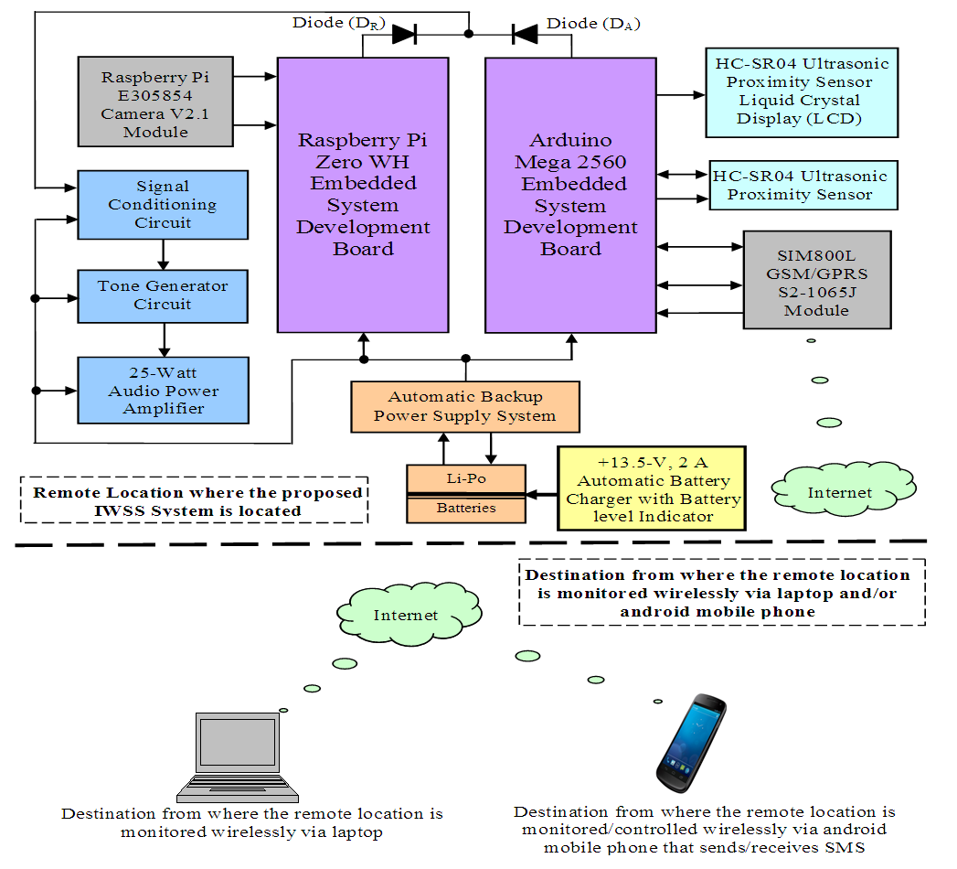 | Figure 1. The block diagram of the proposed integrated wireless security surveillance (IWSS) system |
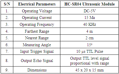
3.2. The HC-SR04 Ultrasonic Proximity Sensor
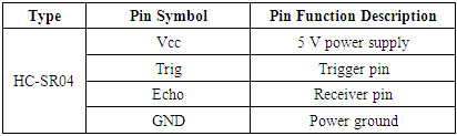
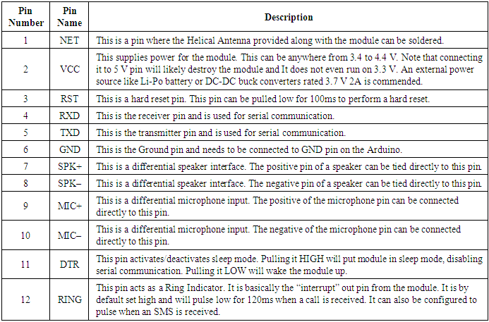
- The HC-SR04 ultrasonic sensor is a device that is capable of measuring the distance to an object by using sound waves [16–19]. It measures by sending a sound wave at a specific frequency and listening for that sound wave to bounce back. By recording the elapsed time between the sound wave being generated and sound wave bouncing back, it is possible to calculate the distance between the sonar sensor and the object. The HC-SR04 ultrasonic sensor used for obstacle detection is shown in Figure 2. The module pin description of the HC-SR04 ultrasonic sensor is shown in Table 1 while the electrical parameters are shown in Table 2.
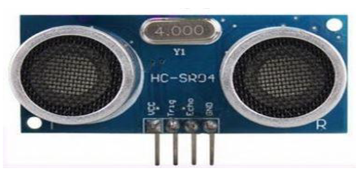 | Figure 2. The HC-SR04 ultrasonic proximity sensor |
|
|
3.3. The YJD1602A-1 16-by-2 LCD Module
- Liquid Crystal Display (LCD) screen is an electronic display module and find a wide range of applications in digital electronic systems [17–20]. The 16x2 LCD display is a very basic module and is very commonly used in various devices and circuits [17–20]. These modules are preferred over seven segments and other multi segment LEDs. The reasons being that LCDs are economical; easily programmable; have no limitation of displaying special and even custom character (unlike in seven segments), animations and so on. A 16x2 LCD means it can display 16 characters per line and there are two such lines. The YJD1602-A LCD module used in this work is shown in Figure 3.
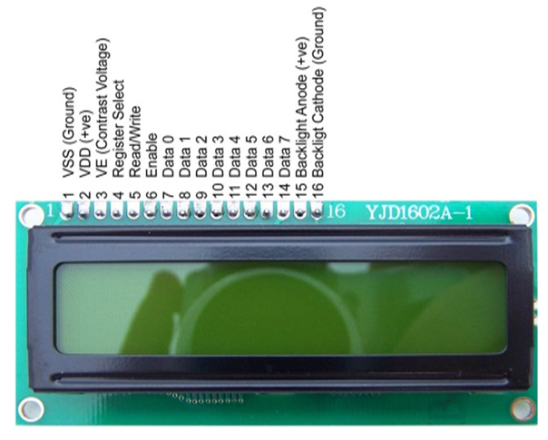 | Figure 3. The physical picture and pin definition of the YJD1602A-1 16-by-2 LCD display module [17–20] |
3.4. The Arduino Mega 2560 Embedded System Development Board
- The Arduino Mega 2560 embedded systems development board shown in Figure 4 is a microcontroller board based on the ATmega2560 [17–19,21]. It has 54 digital input/output pins (of which 15 can be used as PWM outputs), 16 analog inputs, 4 UARTs (hardware serial ports), a 16 MHz crystal oscillator, a USB connection, a power jack, an ICSP header, and a reset button. It contains everything needed to support the microcontroller; simply connect it to a computer with a USB cable or power it with an AC-to-DC adapter or battery to get started. The Mega is compatible with most shields designed for the Arduino Duemilanove or Decimals. The ATmega2560 on the Mega 2560 comes preprogrammed with a bootloader that allows you to upload new code to it without the use of an external hardware Programmer. It communicates using the original STK500 protocol (reference, C header files) [21].
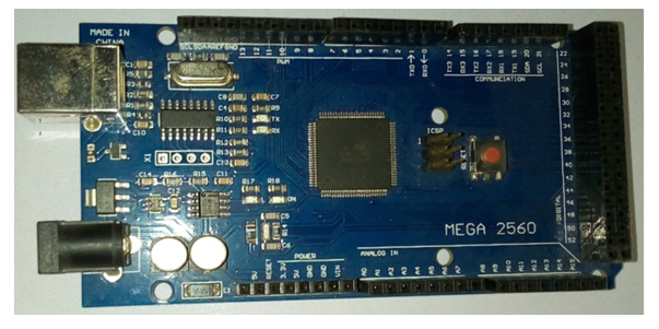 | Figure 4. The top view of Arduino Mega 2560 embedded system development board |
3.5. The Raspberry Pi Zero WH embedded System Development Board [22,23]
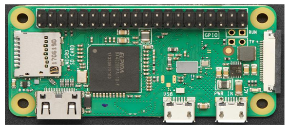
3.5.1. Architectural Description
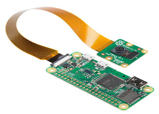
- Raspberry Pi Zero WH embedded system development board is a mini single-chip computer. The top view of the Raspberry Pi Zero WH embedded system development board is shown in Figure 5 [22–23]. Raspberry Pi Zero WH is the smallest chipset in the Raspberry Pi series and is 40% faster than the original Raspberry Pi but nearly half of its size. Raspberry pi Zero GPIO pin-out or Pin diagram, and programming methods are explained in detail in this post. The Raspberry Pi Zero supports mini connectors (like mini HDMI, mini USB power, and USB on-the-go port) to save more space. And the 40pin GPIO is unpopulated which provides the flexibility to use only the connections that the project requires. It consists of a 1-GHz BCM2835 single-core processor, 512 MB RAM, mini-HDMI, USB On-The-Go ports, and a camera connector.
 | Figure 5. The top view of Raspberry Pi Zero WH embedded system development board |
3.5.2. Raspberry PI Zero Power Pins
- The Raspberry Pi board consists of two 5 V pins, two 3.3 V pins, and 9 ground pins (0 V), which are unconfigurable. The 5 V pins directly deliver the 5 V supply coming from the mains adaptor. This pin can be used to power up the Raspberry Pi zero, and it can also be used to power up other 5 V devices. The 3.3 V pin is there to offer a stable 3.3 V supply to power components and to test LEDs. The Ground (GND) pin is from where all voltages are measured and it also completes all the electrical circuits of the board.
3.5.3. Raspberry Pi Zero Input/Outputs Pins
- A GPIO pin that is set as an input pin, receives the incoming voltage signal sent by the device connected to this pin. A voltage between 1.8 V and 3.3 V will be read by the Raspberry Pi as HIGH and if the voltage is lower than 1.8 V will be read as LOW. It is advisable not to supply more than 3.3 V to GPIO pins, or else it will destroy the Raspberry Pi zero board. A GPIO pin set as an output pin sends the voltage signal as high (3.3 V) or low (0 V). When this pin is set to HIGH, the voltage at the output is 3.3 V and when set to LOW, the output voltage is 0 V.
3.5.4. Other Important Pins on Raspberry Pi Zero
- Along with the simple function of input and output pins, the GPIO pins can also perform a variety of alternative functions. Some specific pins are:(a) PWM (pulse-width modulation) Pins: Software PWM available on all pins and Hardware PWM available on these pins: GPIO12, GPIO13, GPIO18, GPIO19.(b) SPI PINS on R-Pi Zero: SPI (Serial Peripheral Interface) is another protocol used for master-slave communication. It is used by the Raspberry pi board to quickly communicate between one or more peripheral devices. Data is synchronized using a clock (SCLK at GPIO11) from the master (RPi) and the data is sent from the Pi to the SPI device using the MOSI (Master Out Slave In) pin. If the SPI device needs to communicate back to Raspberry Pi, the SPI device sends the data back using the MISO (Master In Slave Out) pin. The SPI0 include GPIO9 (MISO), GPIO10 (MOSI), GPIO11 (SCLK), GPIO8 (CE0), GPIO7 (CE1) while the SPI1 consists of GPIO19 (MISO), GPIO20 (MOSI), GPIO21 (SCLK), GPIO18 (CE0), GPIO17 (CE1), GPIO16 (CE2).
3.5.5. I2C Pins on R-Pi Zero
- I2C is used by the Raspberry Pi board to communicate with devices that are compatible with Inter-Integrated Circuit (a low-speed two-wire serial communication protocol for communicating with low-speed peripheral). This communication standard requires master-slave roles between both the devices. I2C has two connections: SDA (Serial Data) and SCL (Serial Clock). They work by sending data to and using the SDA connection and the speed of data transfer is controlled via the SCL pin. The Data pins are (GPIO2) and Clock (GPIO3) while the EEPROM Data ports are (GPIO0) and EEPROM Clock (GPIO1).
3.5.6. UART Pins on R-Pi Zero
- Serial communication or the UART (Universal Asynchronous Receiver / Transmitter) pins provide a way to communicate between two microcontrollers or the computers. TX pin is used to transmit the serial data and RX pin is used to receive serial data coming from a different serial device. The transmitter pin is TX (GPIO14) while the receiver pin is RX (GPIO15).
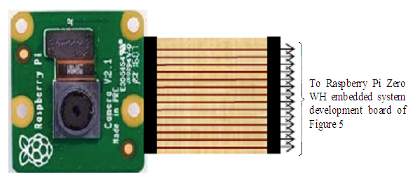
3.6. The Raspberry Pi E305654 Rev 2.1 5-MP Camera Board Module [24–26]
- The Raspberry Pi E305654 Rev 2.1 Camera Module, shown in Figure 6, is a 5 megapixel (5-MP) custom designed add-on for Raspberry Pi, featuring a fixed focus lens [24–26]. The camera module is capable of 2592 x 1944 pixel static images, and also supports 1080p30, 720p60 and 640x480p60/90 video. It attaches to Pi by way of one of the small sockets on the board upper surface and uses the dedicated Camera Serial Interface (CSI), designed especially for interfacing to cameras. In fact, The Raspberry Pi Camera Board plugs directly into the CSI connector on the Raspberry Pi as shown in Figure 7. It is able to deliver a crystal clear 5MP resolution image or 1080p HD video recording at 30fps. The 5-MP native resolution sensor that is capable of 2592 x 1944 pixel static images with Omnivision 5647 sensor in a fixed focus module. Supports 1080p30, 720p60 and 640x480p60/90 video Camera is supported in the latest version of Raspbian, Raspberry Pi's preferred operating system. The camera board module is tiny with a dimension of about 25mm x 20mm x 9mm. It also weighs just over 3 g, making it perfect for mobile or other applications where size and weight are important. It connects to Raspberry Pi by way of a short ribbon cable. The camera sensor has a native resolution of 5-MP, and has a fixed focus lens on-board. In terms of still images, the camera is capable of 2592 x 1944 pixel static images, and also supports 1080p30, 720p60 and 640 x 480p60/90 video recording.
 | Figure 6. The Raspberry Pi E305654 Rev 2.1 5-MP camera board module |
 | Figure 7. The Raspberry Pi E305654 Rev 2.1 camera module with the Raspberry Pi Zero WH board via the 15-pin MPIP CSI cable |
3.7. SIM800L GSM/GPRS S2-1065J Module
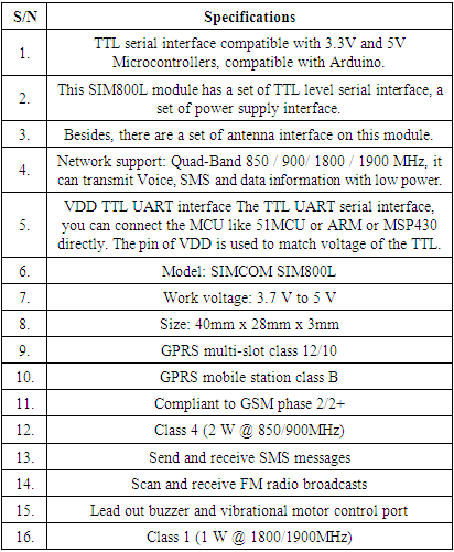
- SIM800L GSM/GPRS S2-1065J module is a miniature GSM modem, which can be integrated into a great number of IoT projects. The SIM800L GSM/GPRS module is shown in Figure 8. This module can be used to accomplish almost anything a normal cell phone can achieve which include but not limited to SMS text messages, make or receive phone calls, connecting to internet through GPRS, TCP/IP, e.t.c [27–29]. In fact, the module supports quad-band GSM/GPRS network, meaning it works pretty much anywhere in the world [27]. The typical specifications of the SIM800L GSM/GPRS module are listed in Table 3 [27–29].
|
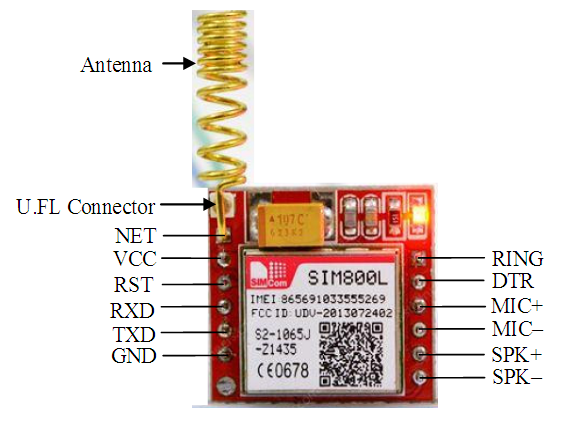 | Figure 8. The SIM800L GSM/GPRS module |
|
3.8. Technical Considerations on Raspberry Pi Zero WH and Arduino Mega2560 Development Tools
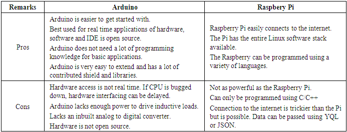
- The raspberry Pi and the Arduino have become invaluable tools [21,22]. They are both extremely popular option and very budget-friendly as well as being suited in their particular applications. Both have their pros and cons as listed in Table 5. Choosing between an Arduino and raspberry Pi depends entirely on the project. Arduino is best suited as interface for tasks that requires reading data from sensors and execute corresponding actions in real-time. Also, Arduino have low power requirements and has very low maintenance requirements. Arduino is ideal for projects that need to be constantly running g with little or no interactions. Raspberry Pi on the other hand should be considered when the task is might need a personal computer to work. The Pi simplifies projects when lots of operations are required to manage. This could be connecting to the internet to read and write data. It could also include jugging media of any kind or connecting to an external display.
|
3.8.1. Raspberry Pi Zero HW Development Tools [22]
- The raspberry Pi is effectively a mini computer on one board, it comes with a dedicated processor, memory, graphic driver, input and outputs like high definition multimedia interface (HDMI). Raspberry Pi Boards runs a specially designed version of the Linux operating system as well. Raspberry Pi is actually a system-on-chip (SoC). It owns a full version of Linux, such as Raspbian, and it is designed to help teach you as you go. Arduino on the other hand is more of a microcontroller than a computer that has a massive support community as well as hundreds of expansion options.
3.8.2. Arduino Mega2560 Development Tools [21]
- Unlike the raspberry Pi development tools, Arduino boards and development tools are actually microcontrollers rather than a full computers. Arduino lacks a full operating system but it can execute programmes that are interpreted by its firmware. Because of this, you do have access to basic tools that operating system would provide but you gain the flexibility of executing code directly with no operating system overhead. Arduino has no API (application programming interface) as there is no operating system. The API is a set of routines, protocols and tools for building software applications. Arduino basically runs code on bare metal.
4. The Development of the Integrated Wireless Security Surveillance (IWSS) System Based on IoT Technologies
- As mentioned in Section 3.1, the two major parts of the IWSS system are the Raspberry Pi Zero WH and the Arduino Mega 2560 embedded system development boards. The Raspberry Pi Zero WH board interface with the Raspberry Pi camera module while the Arduino Mega 2560 interfaces with the SIM800L GSM/GPRS S2-1065J module as shown in Figures 9 and 10 respectively as discussed in the next two sub-sections.
4.1. Raspberry Pi Zero WH Board and the Raspberry Pi Camera Module
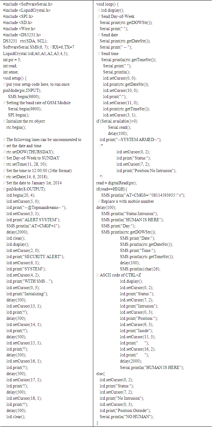
- Interfacing of the Raspberry Pi Zero WH embedded system development board with the Raspberry Pi E305654 camera board module described in Section 3.6 is shown in Figure 9. The camera module is configure in such a way that when the program is compiled, uploaded, and the serial monitor is opened; the camera sends out strings of numbers depending while waiting for moving object detection. When a moving object is detected in front of the camera, the string of numbers produced by the serial monitor stops reading and the object is displayed and the notification “intruder detected, sending text notification” is displayed on the serial monitor. At the instant when the moving object is detected, the blue and green LEDs connected to GPIO3 and GPIO13 respectively turns ON which triggers the electronic alarm system (discussed in Section 4.1.3) via Diodes DR1 and DR2. The Raspberry Pi Zero WH has an IP address of 192.168.43.70.
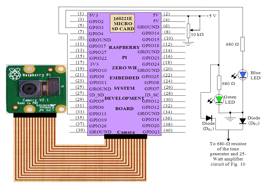 | Figure 9. The Raspberry Pi Zero WH and the remote Raspberry Pi camera system for real-time video streaming |
4.1.1. SIM800L Wireless Connectivity and Obstacle Detection System with Arduino Mega 2560 Board
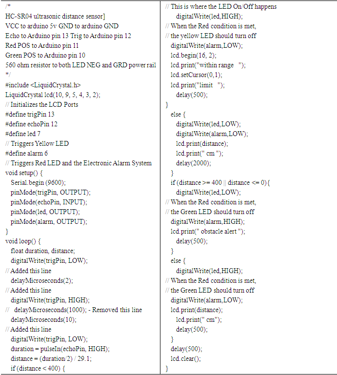
- Interfacing of the Arduino Mega 2560 embedded system development board with the HC-SR04 ultrasonic proximity sensor, YJD1602A-1 16-by-2 LCD module and SIM800L GSM/GPRS S2-1065J module discussed respectively in Sections 3.2, 3.3 and 3.7 is shown in Figure 10. The HC-SR04 ultrasonic proximity sensor is employed here to sense the presence and distance of the approaching object. The Arduino Mega 2560 is programmed in such a way that whenever an object is 2 m closer to the HC-SR04 sensor, the electronic alarm system is triggered and the measured distance is displayed on the YJD1602A-1 16-by-2 LCD module.
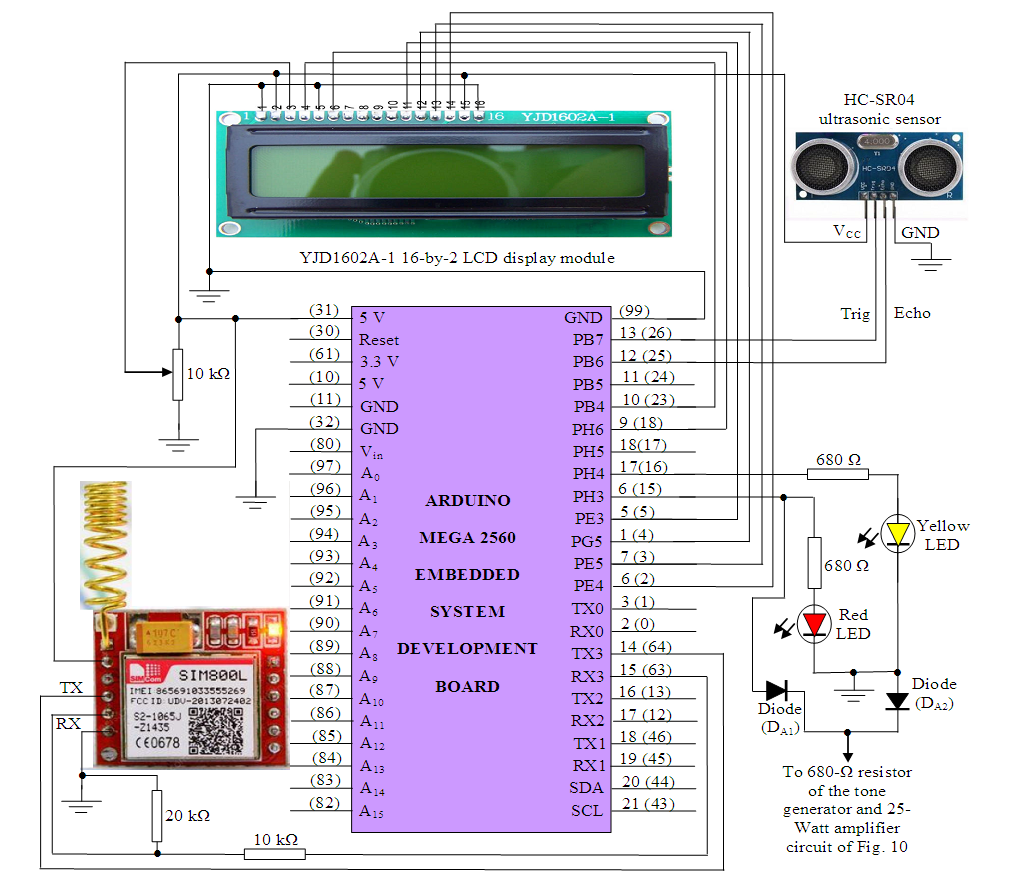 | Figure 10. The SIM800L wireless connectivity and obstacle detection setup for the proposed integrated wireless security surveillance (IWSS) system |
4.1.2. The Electronic Alarm System with a 25-Watt Audio Amplifier
- The block diagram of the IWSS system was described in Section 1 with the introduction of the electronic alarm system incorporating a 25-Watt audio amplifier unit. Here, the complete circuit diagram electronic alarm system is shown in Figure 11 [17,19,30]. The electronic alarm system is built around two NE555CN timer ICs which forms the tone generator and a TDA2050 audio amplifier IC. Following the discussions in previous sections, whenever an obstacle or intruder is detected at a distance of 4 m from the ultrasonic sensor, the electronic alarm system is triggered.
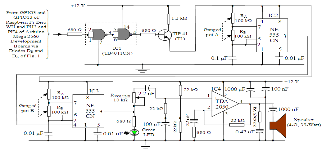 | Figure 11. The complete circuit diagram of the electronic alarm unit with a 25-Watt audio amplifier system [17,19,30] |
4.2. The Power System: Uninterruptible Power Supply with Backup Unit and Automatic Battery Charger
4.2.1. Block Diagram Description of the Power System
- As discussed in Sections 4.1.1 and 4.1.2 using the block diagrams of Figures 9 and 10 respectively, for the proper operation of the IWSS system, the Raspberry Pi Zero WH and Arduino Mega 2560 embedded system development boards and associated components require +5 V while electronic alarm system with the audio power amplifier and associated components require 12-V for optimum performance.The block diagram for the automatic two-way backup power system module supported with a two 12-V Li-Po rechargeable batteries connected in parallel as well as the battery-powered 5-V stabilized power supply unit and automatic battery charger with battery level indicator is shown in Figure 12 while the circuit diagrams of the stabilized dual power supply unit (SPSU) and battery-powered 5-V SPSU are shown in Figure 13 and Figure 14 respectively [18]. As it can be seen in Figure 5, the automation of the power supply module is controlled by two mechanical relays MR1 and MR2.
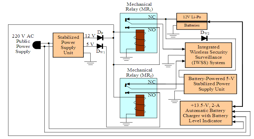 | Figure 12. The block diagram of the proposed automatic two-way backup power supply module |
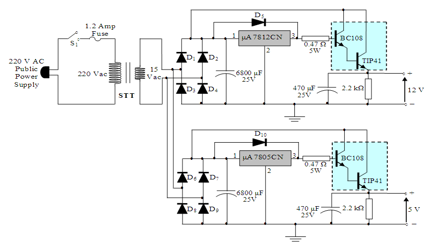 | Figure 13. The circuit diagram of the stabilized dual (+12-V and +5-V) power supply unit based on the availability of public power supply [18] |
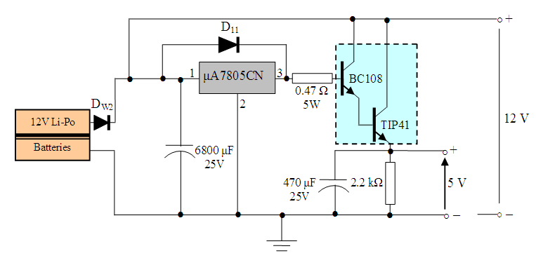 | Figure 14. The circuit diagram of the dual (+12-V and +5-V) power supply units based on the charged two 12-V Li-Po batteries [18] |
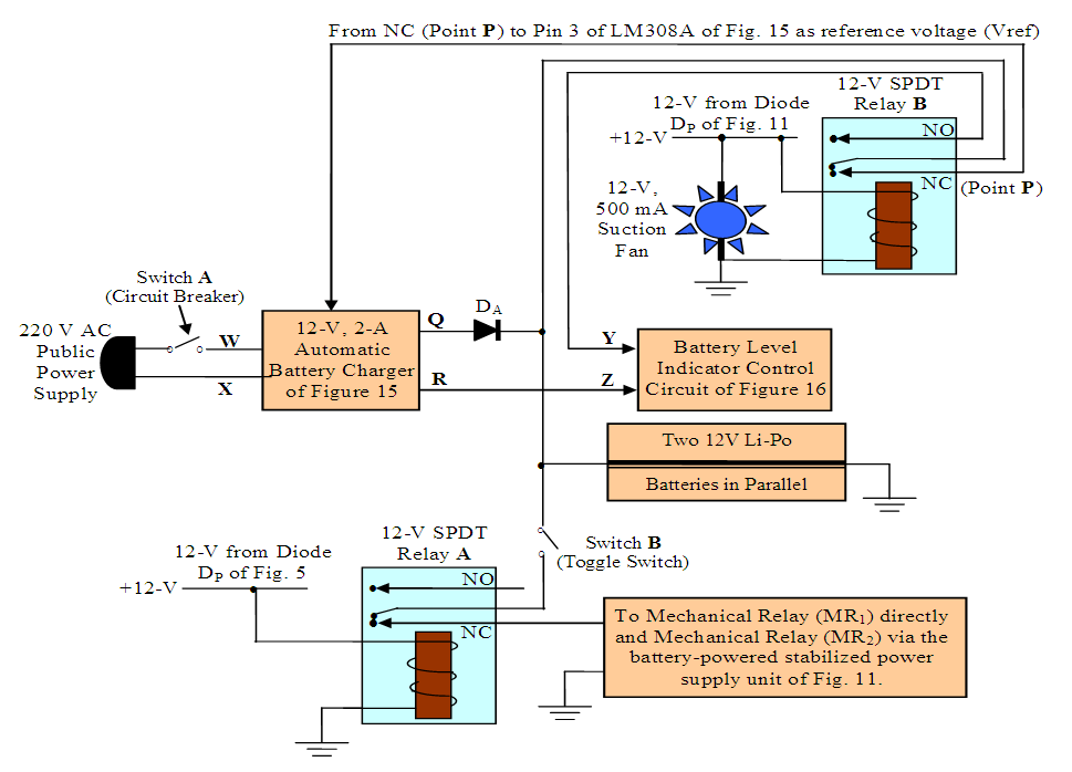 | Figure 15. Block diagram of the automatic battery charger with battery level control unit and mechanical switching SPDT control relays |
4.2.2. Block Diagram Description of the Automatic Battery Charger with Battery Level Indicator Unit and Electromechanical Switching SPDT Control Relays
- The block diagram of the automatic battery charger and all its sub-circuits are shown in Figure 15. Relay A is a 12V 10A 5-pin 2-output (one NC and one NO) electromechanical relay and it is driven by the +12-V biasing circuit of Figure 13 via diode DP in Figure 12 only when PPS is available. Relay B is a 12V 10A 5-pin 2-output (one NC and one NO) electromechanical relay and it is driven by the same biasing circuit of Figure 13 via diode DP in Figure 12 when the two Li-Po batteries is in used during the absence of PPS. The circuit of transformer STT, diodes D1-D4, voltage regulator μA7812CN and transistors BC108 and TIP41 is a biasing circuit that triggers Relay A. This circuit is driven only by the public power supply when available as shown in Figure 13. In a similar way, the circuit of Figure 14 is also a biasing circuit that is energized only in the absence of public power supply but provided that switch B is closed (i.e. the two Li-Po 12-V batteries are use in this operation). This circuit drives the 12-V 500 mA cooling suction fan and turns ON the battery voltage level indicator through Relay B in the NC position. The remaining two blocks: the automatic battery charger and the battery voltage level indicator are described in the next sub-sections 4.2.3.Relay A plays a significant role in the overall switching of the load between the battery backup power system and the public power supply. In the presence of the public power supply with switch B ON, Relay A is triggered (switched to NO). At this instance, the IWSS system is power directly from the public power supply and the batteries are equally charged by the automatic battery charger. However, in the absence of the public power supply, the relay A and relay B are both switched OFF. Thus, input terminals of both relay are connected to their respective NC terminals. At this instant and with toggle switch B closed, the cooling fan and the battery voltage level indicator switches ON simultaneously and the IWSS system is powered by the battery backup system.
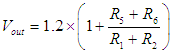
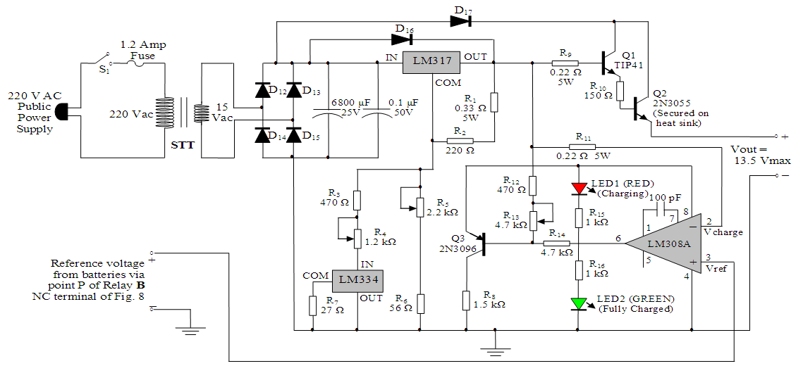
4.2.3. The Automatic Battery Charger and the Battery Voltage Level Indicator
- The two circuits shown in Figure 16 and Figure 17 are the automatic 15 V-dc battery charger and the battery voltage level indicator respectively [31]. The battery charger designed for this inverter is a high performance charger with self regulating features. The main integrated circuit voltage regulator is the LM317 whose output voltage is fixed at 13.5 V using the resistors values defined by Equation (1) and shown in Figure 16 [32]:
 | (1) |
 | Figure 16. An automatic 12-Volt battery charger with automatic cut-off at full charge. Note that Vout = 13.5 Vmax is the output voltage to 12V Li-Po battery and Relay B shown in Figure 15 [31] |
 | Figure 17. Battery voltage level indicator circuit [31] |
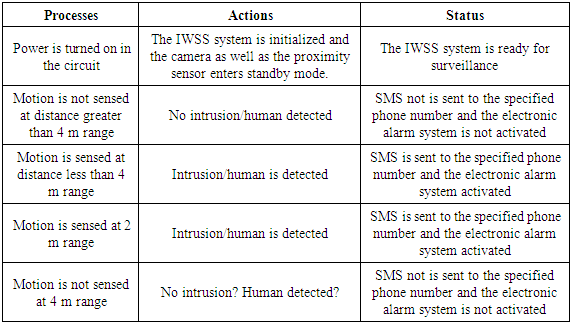
4.3. IWSS System Integration, Deployment and Testing
- The developed IWSS was deployed for security surveillance at the Department of Physics Electronics, The Federal University of Technology, Akure – Nigeria and its operation as well as its performance met the specific design objectives without human intervention.The Arduino Mega 2560 controls the SIM800L GSM/GPRS S2-1065 module which sends only SMS to the specified mobile number based on the situation in the environment under surveillance should there be any form of intrusion while the Raspberry Pi Zero WH is used for streaming the real-time video of the environment under surveillance as viewed by the Raspberry Pi E305654 5-MP camera module.The process, action and the status of the IWSS system during testing is summarized in Table 6. The flowchart for the complete operation of the IWSS system is illustrated in Figure 18 in conjunction with Table 6. once the IWSS system is powered ON, the Raspberry Pi Zero WH embedded system development board, the raspberry Pi E305854 camera module, the Arduino Mega 2560 embedded system development board, the SIM800L GSM/GPRS S2-1065J module and the HC-SR04 proximity sensor are initialized. This is immediately followed by the scanning of the Raspberry Pi camera and the proximity sensor for object detection. The Raspberry Pi camera starts delivering real-time streaming videos to the destination IP address on both android mobile phone and the HP laptop (whether or not a moving object is detected by the camera). However, once any moving object is detected at a distance of less than 4 m, an SMS is sent to the specified destination phone number while the electronic alarm system is automatically activated as an indication of the presence of an intruder.
|
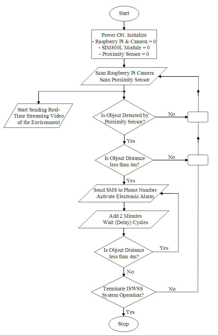 | Figure 18. Flowchart for the operation of the IWSS system |
 | Figure 19. Motion detection in real-time video streaming using an android phone for Case 1 |
 | Figure 20. Motion detection in real-time video stream using an android phone for Case 2 |
 | Figure 21. Motion detection in real-time video stream using an Hp Laptop for Case 3 |
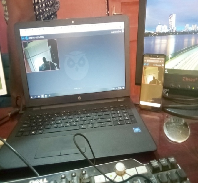 | Figure 22. Motion detection in real-time video stream viewed simultaneously on android phone and Hp Laptop for Case 4 |
5. Conclusions
- A novel integrated wireless security surveillance (IWSS) system has been designed, developed, constructed and deployed for security surveillance. The performance of the IWSS system has been investigated and operation of the system satisfies the design objectives. The results show that it can potentially be used for community based home security system by taking the advantages of wireless mesh network. Furthermore, it can eliminate blind spot, where the sensor and the camera can be placed at hidden places for enhanced detection and human face recognition. Multiple sensors and cameras deployment also can be placed at many locations. In addition, the system networking can be expanded throughout residential area by deploying additional open-mesh wireless mesh router, camera nodes, and sensor nodes. The low cost for the production and deployment of the IWSS system makes it an excellent product for the security surveillance of residential communities.The developed IWSS system can be adapted for complete home and community as well as shopping mall automation for intrusion detection and notification. Rather than triggering the electronic alarm system for all human faces, facial image recognition algorithms can be incorporated to trigger the alarm for only unknown facial images [34–36]. The developed IWSS system also be adapted for much longer distances by the use of LiDAR sensors [17].
Appendix
|
|
|