Konstantinos Kalovrektis1, Apostolos Xenakis1, Ioannis Korinthios1, Athanasios Kakarountas2, Antonios Gotsinas3, George Stamoulis1
1Department of Computer Science and Telecommunications, University of Thessaly, Lamia, Greece
2Department of Computer Science and Biomedical Informatics, University of Thessaly, Lamia, Greece
3Department of Computer Science, University of Piraeus, Piraeus, Greece
Correspondence to: Konstantinos Kalovrektis, Department of Computer Science and Telecommunications, University of Thessaly, Lamia, Greece.
| Email: |  |
Copyright © 2020 The Author(s). Published by Scientific & Academic Publishing.
This work is licensed under the Creative Commons Attribution International License (CC BY).
http://creativecommons.org/licenses/by/4.0/

Abstract
Several studies related to treatment of Parkinson's disease, have been performed, using mechanical support methods. Most of these studies use accelerometer technology to track the patient's movement with Parkinson's disease, as it enables the recording of full motion range and acceleration in all directions, with great accuracy. With our proposed system, we aim to reflect the patient's hand movements, in real time, as accurately as possible in a robotic arm located remotely inside a laboratory. Additionally, our system records data concerning Parkinson's patient trembling and transmits absolute position and acceleration regarding two points, i.e. the elbow and the wrist. To do so, we design a lightweight - custom ZigBee protocol, with which the wireless sensors transmits data in an IoT fashion.
Keywords:
Parkinson, Robotic Arm, IoT, Wireless Sensor Network, ZigBee, Medical Model design
Cite this paper: Konstantinos Kalovrektis, Apostolos Xenakis, Ioannis Korinthios, Athanasios Kakarountas, Antonios Gotsinas, George Stamoulis, An IoT – Sensor Based Hand Trembling Robotic System for Studying Parkinson’s Symptoms, International Journal of Internet of Things, Vol. 9 No. 1, 2020, pp. 12-19. doi: 10.5923/j.ijit.20200901.02.
1. Introduction
Parkinson's disease is a progressive neurodegenerative disorder, associated with dysfunction or loss of dopaminergic neurons in the brain, lack of dopamine, and the formation of abnormal protein particles, the lewy bodies, in neurons [1]. It is an idiopathic disease of the nervous system, characterized by motion and non - motion manifestations, such as tremble (or tremor). James Parkinson has described the disease since 1817. The disease is associated with significant disability and overall low quality of life. Tremor is a rhythmic, involuntary muscular activation at an almost fixed frequency and amplitude, which is a symptom of several neurological disorders and neurodegenerative diseases, such as the Parkinson's.Tremor commonly affects the upper limbs [7]. An occupational therapist can pinpoint everyday tasks that PD can make problematic, and they can help find practical solutions. Examples include helping people with techniques for getting dressed, preparing meals, performing household chores, and doing the shopping. There are methods that support the treatment of the disease, using robotic technology that helps to dampen the vibration of tremor in patients with Parkinson's [4] [7]. However, until nowadays, there has been no physical model that accurately reflects the oscillation of a patient's upper limbs on a robotic arm, to be used as a study mechanism in order to develop motion-damping techniques.In this paper, we develop a robotic system for recording the movements of a patient with Parkinson's, that records and transmit absolute position and acceleration from two body points, the elbow and the wrist. These measurements can be transmitted using a sensor network in a wireless fashion, using a customized lightweight ZigBee protocol version. Moreover, data can be available for further analysis via open source IoT platform, like Think Speak [11]. The most important contribution of this paper is that with our system, we may reflect the patient trembling into a robotic arm, with which doctors can study the patient’s symptoms in real time and from distance. In order to facilitate energy efficient data communication, we also enhance our system design with a customized ZigBee protocol version, suitable for small sensors mounted on patient’s wrist and elbow. Several medical studies related to the treatment of Parkinson's disease using mechanical support methods [2]. These methods are based on a combination of electronic and mechanical devices that are mounted on patients. These devices locally record trembling related data and may be used to reduce that trembling. However, a study focusing on studying Parkinson's symptoms uses a dynamic robotic hand model that allows degrees of freedom in human hand movement, is found in [1]. A mechanical analogy of the physiology and function of the human arm, is depicted in Fig. 1.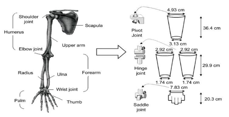 | Figure 1. Dynamic Model of a human hand [1] |
In this study, a vibration absorber is designed to diminish tremor in human hand. The study also showed that using a dynamic hand model that reflects the movements of a Parkinson's patient, is an important tool in trying to find cure paths for the disease. Using the design data of the human hand model, already proposed in [3], we could design and build a robotic arm that can simulate in detail the movements of a real human hand. Therefore, using a system to record the movement of a patient's actual hand with Parkinson's, we can collect appropriate tremble data and feed it to a robotic arm that will simulate the patient's conditions. With this method, we can create a remote symptoms study tool for the disease, which may significantly contribute to the discovery of optimization techniques regarding mechanical support systems, able to provide cure solutions for the disease, in the end. A typical figure of such system is depicted in Fig. 2 as follows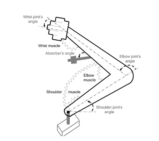 | Figure 2. Robotic Musculoskeletal human hand |
Additionally, several studies have been performed regarding the wearable medical devices, used to record the movement and trembling, which transfer their sensing data over the Cloud with IoT technology [2] [3] [4]. Many of these studies use accelerometer technology to track the patient's movement, as it enables them to record the full motion range and acceleration in all directions with high accuracy. The wireless data transmission is done using well known protocols, such as Bluetooth, WiFi and ZigBee [3] [4]. In our proposed system, we adopt ZigBee protocol for medical data transmission; however, we enhance the wireless capability of our system with a customized lightweight ZigBee – version, for better scalability and energy efficiency. We manage to connect many sensor devices in real time, to a central network coordinator, minimizing delays, potential interferences and pointless energy consumption. The paper is organized as follows: In section 1, we gave an Introduction regarding the necessity of robotic arm solutions in studying Parkinson’s disease and focused on several studies. In section 2, we give the technical details regarding our system design solution, in terms of hardware usage and communication protocol. In section 3, we give some data results and finally we conclude the paper.
2. System Model Design
In this section, we provide all details regarding the proposed system design. We also test our system’s response in terms of real data acquisition and processing.
2.1. Hardware Design and Integration
The aim of our proposed system is to reflect the patient’s hand movement as accurately as possible in a robotic arm, possibly located in a remote laboratory. The movement recording is performed in two levels, for great accuracy, at the height of the elbow and at the top of the palm. In addition to recording the absolute position of the patient’s hand, the acceleration in the direction of the movement, is also recorded. For this reason, an accelerometer and a gyroscope are used, which are integrated in a single chip in order to capture the required measurements. The integrated circuit used is the MPU 6050 [5], which enables interconnection with microcontrollers via I2C interface [5]. The integrated is depicted in fig. 3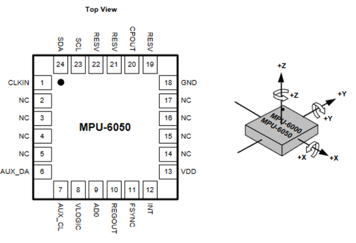 | Figure 3. Integrated circuit board MPU 6050 [5] |
The MPU6050 integrated circuit requires a microcontroller with an I2C module to be loaded with the appropriate firmware to operate it. As shown in fig. 3, the three – axis position and angular velocity data from the MPU6050 should be transmitted wirelessly to a data center and be connected via an IoT platform to a data channel that can be accessed by medical research personnel. The block diagram of MPU6050 is depicted in the following fig. 4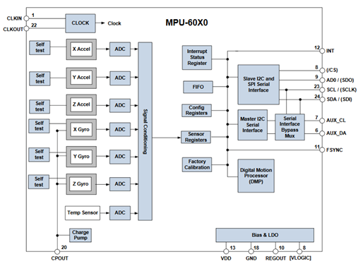 | Figure 4. Block diagram of MPU 6050 [5]. |
For the wireless data transmission, we use a modified communication protocol, based on the IEEE 802.15.4 standard [11] [12]. The hardware chosen to enable this type of wireless communication, in our proposed system design, is the CC2538 integrated circuit [10], which incorporates a wireless communication transceiver, based on the IEEE 802.15.4 standard, together with a very powerful ARM Cortex – M3 microcontroller, clocked at 32MHz. The integrated circuit, supporting some passive components outside, directly activates a wireless transceiver for transmitting communication packets that follow the IEEE 802.15.4 standard frame format, as well as allows the application programming on the same chip due to its integrated microcontroller. Packet authentication, data transfer security mechanism with 128 – bit AES encryption, connection quality control and wireless communication channels as well as communication packet integrity control, are integrated functions in the circuit, so as not to burden the firmware that must be loaded on the microcontroller to operate it. The transceiver, as well as the MPU6050, will be driven by the firmware that we load in the memory of the ARM Cortex – M3 microcontroller. 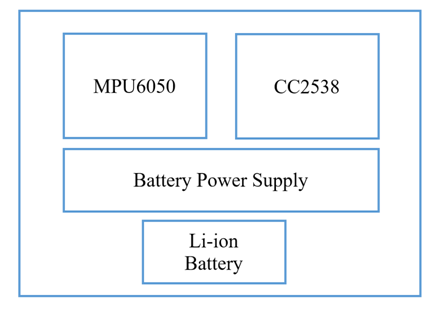 | Figure 5. Wireless accelerometer node Block Diagram |
As also shown in fig. 5, the MPU6050 integrated circuit, requires two communication lines, based on the Philips I2C standard. The ARM Cortex – M3 microcontroller integrated into the CC2538 integrated circuit, has an I2C module that can be properly configured to generate the signals required to communicate with the MPU6050 circuit. The power supply circuitry for the proposed system, uses the integrated circuit NCP1402 [12], which allows the battery voltage to be raised to the 3.3V required to cover part of the device's circuitry.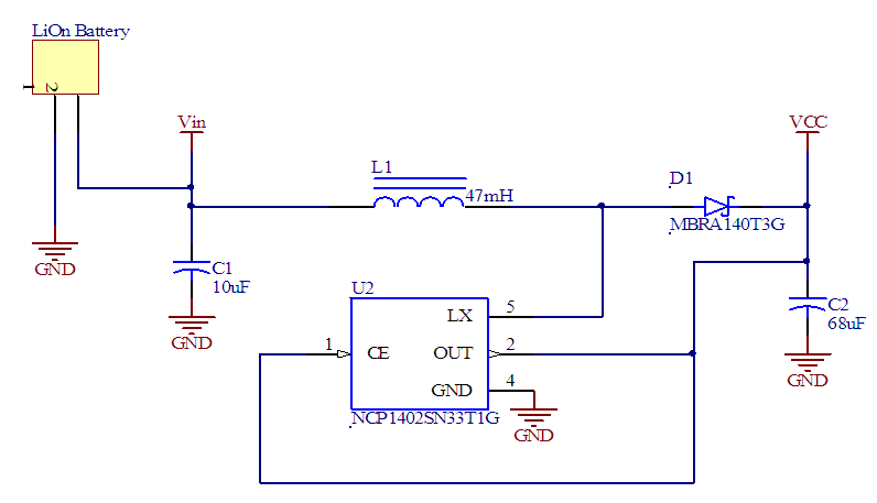 | Figure 6. NCP1402 connection diagram for 3.3V voltage level |
2.2. ZigBee Customized Wireless Protocol
The proposed system requires a communication protocol for remote measurement control and acquisition of signals from patients, who take part in an experimental measurement process. The proposed measurement system aims to improve the measurement process by facilitating the placement, measurement and processing of data from different samples of individuals. To this end, this process requires a flexible method of communication that can serve the need for remote communication from two or more nodes simultaneously, in a secure and reliable data transfer manner. The use of the integrated CC2538 transceiver activates a large set of capabilities in wireless communication among the nodes that will take part in the wireless communication network, using the PHY layer and the MAC layer, as specified by IEEE 802.15.4. Thus, in this work, we propose a customized communication protocol version, that will use the PHY and MAC layer of 802.15.4, which is the lower levels of ZigBee. In fig. 7, we depict our custom protocol stack design.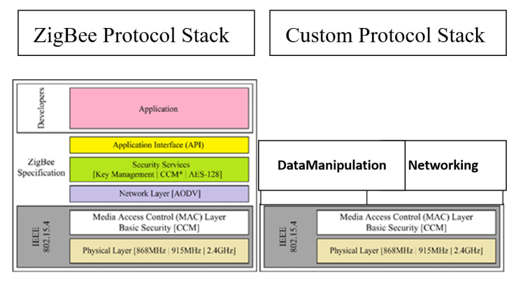 | Figure 7. Custom protocol stack (right) as compared to 802.15.4 stack (left) |
According to [8] [9], IEEE 802.15.4 protocol functions are related to the first two layers, i.e. the physical layer and the data link layer. The upper layers, i.e. the network, the security and the application layers, use mechanisms related to data routing, communication reliability and maintenance, nodes control and data integrity. The upper layers of the ZigBee protocol stack, such as network layer, security layer and application layer, use data routing mechanisms, maintaining the communication between nodes, controlling the status of each node, controlling data integrity and security and more generally uses mechanisms that meet the networking and communication needs of a large set of applications. The most vital layers to achieve a two – way wireless communication and to identify nodes and their addresses in a secure way are the Physical and Data Link layer. Therefore, for the purpose of this work, we designed a simplified and lightweight ZigBee – based version of the network layer, which applies a connection and disconnection node management mechanism. Additionally we implemented a data management mechanism at MAC layer, which encapsulates data measurements inside frames and prepares their transmission at PHY layer. As shown in fig. 7, our customized protocol uses the two lower PHY and MAC levels of ZigBee. Our proposed communication protocol defines two types of devices, which are a Coordinator and one or more measuring devices, called Signal measurements sensor nodes. The coordinator is a device node, responsible for setting and controlling the wireless communication network, which facilitates the sensor nodes’ connection to it. The communication network will be characterized by a unique PAN-ID address (Personal Area Network – ID), which is selected by the coordinator. Therefore, all sensor nodes are connected and controlled by the controller, as they get connected to the network. The protocol design defines the following communication processes: Ø Network Creation process: In this process, the coordinator, establishes a new connection, using an available wireless channel, and defines a unique PAN-ID network address. When this process is completed, all other nodes can be connected to the network afterwards. Ø Node Connection process: Via this process, a node is connected to the network. Upon connection, each node is considered as active and checks its memory for network connection information. If no network association information is present, the node sends an Association Request packet to the coordinator and waits for an Acceptance or Rejection packet reply. In case of an Acceptance packet, the coordinator sends back to the node another packet, containing network connection information. This information is a unique 16 – bit node address, used for network communication. Ø Node Task process: During periodic intervals, each node sends a request to the coordinator, to ask if it should perform any task, assigned by the coordinator. Otherwise, nodes choose to sleep in order to consume less energy. For this reason, each node’s transceiver is not active all the time. On the contrary, all nodes take turns and activate their transceivers, for a certain period of ms time, or the coordinator wakes the nodes up, upon system user request. Then the coordinator, choose each node accordingly to perform a task. Ø Node disconnection process: Through this process, the coordinator decides which node remains network – active and which gets disconnected. For this reason, the coordinator sends a Disassociation Notification packet to the node that is going to be disconnected. Afterwards, the node erases the connection information from its memory. Finally, the node is considered as unknown node to the network. Ø Node’s State Information process: During this process, the coordinator sends a Network State Request packet to all network nodes. As soon as the nodes receive this packet, they take turns and send a request for transmission (i.e. action request packet). Afterwards, each node that has information to send, prepares and sends a packet including its battery status and data measurements.During the node connection process, when the coordinator receives an Association Request from a node, it processes the request and produces a unique 16 – bit address, which is attached to an Association Response packet. The network coordinator chooses a fixed 16 – bit address like 0x0000. The nodes’ address values are as follows: 0x0001, 0x0002, etc. The last value if 0xFFFD (in total 65535 addresses). The coordinator is responsible for assigning each node with a unique address and avoid a potential address value conflict, during new network associations. Except the aforementioned short fixed hex value addresses, each node is also associated with a unique MAC address. Additionally, each node also maintains, in its memory, a connection table. The connection table shows information regarding the associated nodes with the coordinator. In particular, the table maintains tuples regarding the 64 – bit hex coordinator’s address and the short 16 – bit address values. To this end, each node’s table contains one tuple (i.e. its connection with the coordinator). On the contrary, the coordinator’s table contain as many tuples as the number of connected network nodes.
2.3. Robotic Arm Design and Operation
The robotic arm was designed according to the guidelines of an article published by Frontiers of Neurorobotics [6] using a 3D printer. The servomotors and design method activate the degree of freedom in movement, as it is a real hand. As shown in fig. 8, servomotors are mounted on the robotic arm to offer the required degree of freedom in movements. 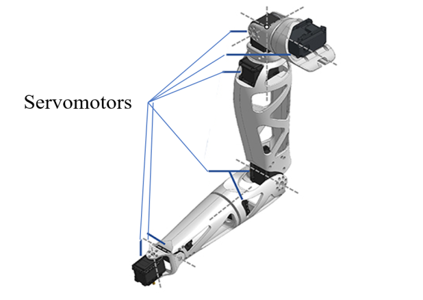 | Figure 8. A Human – like 3D printed Robotic Arm |
The robotic arm if controlled by a USB controller, connected to the computer, and the data transfer and motion control commands is done through serial commands [6]. To control the system, two wireless accelerometer nodes are placed in the upper part of the palm and inside the elbow of the patient, as shown in fig. 9. Each node has its own unique network address and the coordinator collects data. The sensors form a local network of sensors. The coordinator also acts as a web server, thus enabling data transfer via the home router to the Cloud and the IoT Platform. The coordinator is connected to the Router via an Ethernet interface. In fig. 9, we depict the operational block diagram of the proposed system, in which the medical sensors communicate with the coordinator, the coordinator is connected to the Router and through Cloud and IoT technology, and movement data is transmitted for further analysis. The remote robotic arm moves at the exact same way as the Parkinson’s patient does.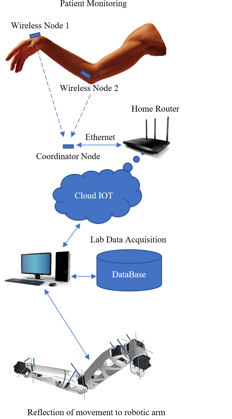 | Figure 9. System’s Operational Diagram |
The data is recorded, in real time via Cloud, on a specific IoT channel, that is accessible by authorized personnel. Because IoT platforms support long refresh intervals, the coordinator is equipped with a data storage buffer that records data for 15 seconds to keep up with the refresh rate. Afterwards, data can be stored to local medical databases for further pattern analysis regarding trembling frequencies. The robotic arm, connected to a computer, extracts the data from the database and reproduce the patient’s movement as recorded by the local sensor attached to the patient’s wrist and elbow. The proposed system provides the user with the ability to control the measurements, sending commands through a special IoT data channel, related to the beginning and the end of the measurement session.
3. IoT Connection and Data Processing
LabVIEW interface contains a set of virtual programming tools that helps users to easily program applications that receive data from an external environment [13]. Additionally, LabVIEW, uses NI VISA drivers to provide an interface with the external environment via the computer’s COM serial communications ports using RS-232 protocol. The software components, and their interconnections, as used according to our design for our proposed data collection System, is depicted in fig. 10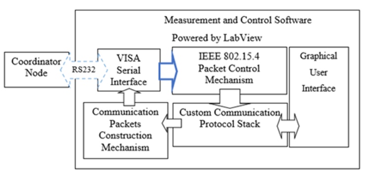 | Figure 10. Structural design of human movements system |
Using LabVIEW’s front panel, we have a graphical way, via which we can easily tune our system’s settings, and control the measurement and evaluation process [13]. The data coming from the coordinator node, correspond to the communication packets of our proposed lightweight protocol, have hexadecimal values due to their formatting process conducted by the coordinator’s software. For this reason, our software apply decoding processes, which identifies the packet types and categorizes them. This packet communication decoding mechanism, checks if there exists data on the serial interface, coming from the coordinator, and depending on the length of the data inside the register’s reception port, decodes properly all incoming packets to ZigBee – compliant packets. By using a signal measurement node and properly placing it on a patient, we connect this node to the network coordinator and it appears in the Associated Nodes table in the graphical interface environment.. Our system also supports data storage for a certain period, in case of further off – line processing.Using LabVIEW’s environment capabilities, we can collect the signals and store them for further processing. We can also apply one of the most popular IoT platforms and data communication protocols [14] (i.e. MQTT, CoAP, AMQP, WebSocket, Node) and open a web portal, from which the medical staff and researchers. In our proposed system, we design a proper mechanism for collecting and transferring our data to the ThingSpeak [11] IoT platform, which enables us to create channels that can accommodate eight value fields each.In fig. 11, we depict a command snapshot regarding the connection of LabVIEW data collection environment with ThingSpeak IoT platform. To this end, through specific API connections [11], patient signals reach ThingSpeak platform.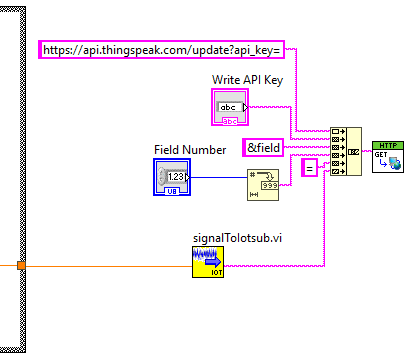 | Figure 11. LabVIEW connection commands for ThingSpeak Platform connection |
For each patient’s, the data samples arriving at the coordinator, is recorded in the central control system and fed into the IoT platform, each measured data per channel. Each communication channel can support up to four different patients. Each patients’ finger device has a unique address within the wireless network. Therefore, it seems like assigning a specific unique ID number to each patient for monitoring purposes. In this way, it is possible the IoT platform user to distinguish which channel field corresponds to which monitored patient.In fig.12 we depict voltage data, concerning the movement of the lab robotic arm, which in essence depicts real time the patient’s trembling. The mean voltage (mV) value is 26 and the standard deviation is 15, 28. These values concern a time series window of 100 sec, for one patient. Peak values (i.e. greater than 40 mV) depict higher trembling frequency, which means that that the patient’s movements and acceleration is higher. This is translated to the exact movement and rotation angle of the robotic arm in the remote lab facility. 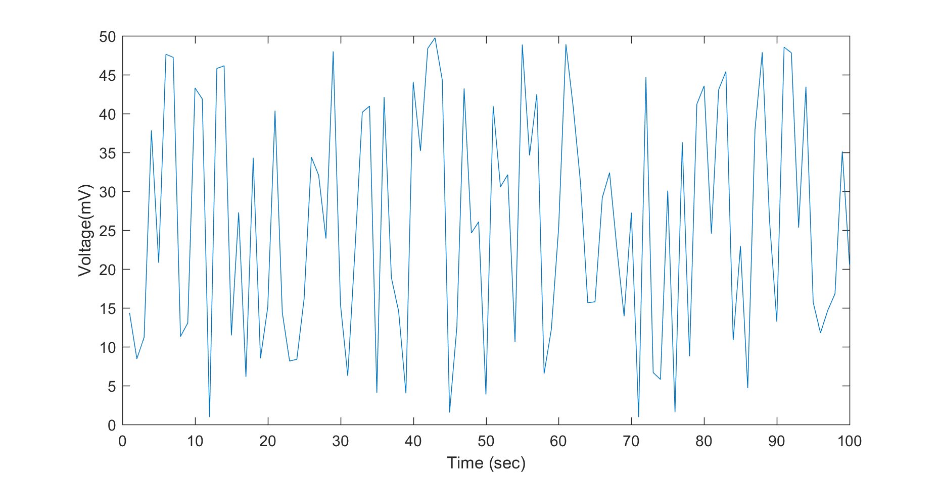 | Figure 12. Data measurements |
Overall, our proposed system uses low – power electronic com-ponents, which allow the circuitry to operate with a single AAA battery or with any battery with a voltage range from 0.8V up to 3V. In case of idle state, the microcontroller sets the most energy - hungry internal components, such as amplification and filtering circuits, in a low – power state. According to our proposed lightweight protocol version of ZigBee, each node transits to low power consumption state and activates its transceiver only at regular intervals or when new data needs to be transmitted.As far as LabVIEW control software is concerned, it is easily modifiable, if necessary, to meet user needs via serial commands, which pass towards the coordinator. Following, according to our software design, we provide the developer with simple serial commands, containing the address of the node to reach and focus on a specific plant. In other words, the user of our software could intervene to a specific node, as long as the node’s address is within the coordinator’s association table. If so, the coordinator sends a message informing the user of the status of the node and prompts the user to wake the node up to perform a measurement. The data we collect can be stored to memory slots or a database or to be exported to spreadsheets for further analysis. We chose LabVIEW programming environment for control and data processing because of its rich processing tools for bio signals.
4. Conclusions
In this paper, we design and propose a robotic arm system in which we aim to reflect the patient’s hand movements, in real time, as accurately as possible. Our system records data concerning trembling from sensors attached to wrist and elbow of a patient. Data concerning absolute position and acceleration of these points are transmitted wirelessly and via the internet towards an open source IoT platform, where medical authorized personnel proceed with further analysis. To do so, we also design a lightweight – custom made ZigBee protocol, with which the wireless sensors transmit data in an energy efficient manner towards the IoT platform. Sensor nodes connect to the network controller in a one – hop fashion and are uniquely distinguishable in terms of network identity, via their Hex address values and MAC addresses.Our system was tested using Think Speak IoT platform, which has a data refresh rate every 1 second, resulting in an almost real time data recording with the coordinator buffering capacity. We use 2 communication channels, one to record the patient’s hand movement and the other to send control and measurement data. Data recording from the proposed wireless sensor system power the robotic arm driver software, which perform almost identical movements in XYZ axis and reaches 98% accuracy. The movement measurement was recorded for 100 seconds, while the patient tried to perform daily movements, such as trying to open the tap of a bottle and fill a glass with water. The movement reflection in a robotic arm revealed that is can be used as a guide to construct mechanical support elements to help diminish hand trembling for patients. The system can also be used remotely to allow authorized medical personnel to study Parkinson’s symptoms, in real time. The ability to store and reproduce movement for specific daily activities of a patient with Parkinson’s, is a serious subject of medical study by neuroscientists and doctors in search of finding a cure for the disease.
References
| [1] | Gebai, Sarah & Hammoud, Mohammad. (2016). Parkinson’s Disease Treatment as Seen from a Mechanical Point of View. Advances in Parkinson's Disease. 05. 97-106. 10.4236/apd.2016.54012. |
| [2] | Romero, L.E., Chatterjee, P. & Armentano, R.L. An IoT approach for integration of computational intelligence and wearable sensors for Parkinson’s disease diagnosis and monitoring. Health Technol. 6, 167–172 (2016). |
| [3] | R. LeMoyne, C. Coroian and T. Mastroianni, "Quantification of Parkinson's disease characteristics using wireless accelerometers," 2009 ICME International Conference on Complex Medical Engineering, Tempe, AZ, 2009, pp. 1-5. |
| [4] | J. Cancela et al., "Gait assessment in Parkinson's disease patients through a network of wearable accelerometers in unsupervised environments," 2011 Annual International Conference of the IEEE Engineering in Medicine and Biology Society, Boston, MA, 2011, pp. 2233-2236. |
| [5] | Inven Sense, "MPU-6000 and MPU-6050 Product Specification Revision 3.4", 2013. |
| [6] | Mick S, Lapeyre M, Rouanet P, Halgand C, Benois-Pineau J, Paclet F, Cattaert D, Oudeyer P-Y and de Rugy A (2019) Reachy, a 3D-Printed Human-Like Robotic Arm as a Testbed for Human-Robot Control Strategies. Front. Neurorobot. 13:65. doi: 10.3389/fnbot.2019.00065. |
| [7] | D. Huen, J. Liu and B. Lo, "An integrated wearable robot for tremor suppression with context aware sensing," 2016 IEEE 13th International Conference on Wearable and Implantable Body Sensor Networks (BSN), San Francisco, CA, 2016, pp. 312-317, doi: 10.1109/BSN.2016.7516280. |
| [8] | IEEE Std 802.15.4-2006, “Part 15.4: Wireless Medium Access Control (MAC) and Physical Layer (PHY) Specifi-cations for Low-Rate Wireless Personal Area Networks (LR-WPANs),” 2006. |
| [9] | IEEE Std 802.15.4a-2007, “Amendment to 802.15.4-2006: Wireless Medium Access Control (MAC) and Physical Layer (PHY) Specifications for Low-Rate Wire-less Personal Area Networks (LR-WPANs),” 2007. |
| [10] | CC2538 Powerful Wireless Microcontroller System-On-Chipfor 2.4-GHzIEEE 802.15.4, 6 LoWPAN, and ZigBee®Applications. (2015, April). Retrieved from https://www.ti.com/product/CC2538. |
| [11] | ThinkSpeak IoT platform, available at: https://thingspeak.com/. |
| [12] | NCP1402 Data Sheet, available at: http://suo.im/5FpBZu. |
| [13] | LabVIEW functionalities [On line], available at: http://zone.ni.com/reference/en-XX/help/371361R-01/lvconcepts/functions_overview/. |
| [14] | MQTT, The Standard for IoT Messaging [On line], available at: https://mqtt.org/. |

 Abstract
 Reference
 Full-Text PDF
 Full-text HTML