-
Paper Information
- Previous Paper
- Paper Submission
-
Journal Information
- About This Journal
- Editorial Board
- Current Issue
- Archive
- Author Guidelines
- Contact Us
International Journal of Internet of Things
2017; 6(2): 88-90
doi:10.5923/j.ijit.20170602.17

IoT Based Energy Meter (AMMP)
 Abstract
 Reference
 Full-Text PDF
 Full-text HTML
Mabel Philip, Princia Jovita Mendonca, Aparna Thampy, Melvita Menezes, Renuka Tantry
Department of Computer Science and Engineering, SJEC, Vamanjoor, Mangaluru, India (VTU)
Correspondence to: Princia Jovita Mendonca, Department of Computer Science and Engineering, SJEC, Vamanjoor, Mangaluru, India (VTU).
| Email: |  |
Copyright © 2017 Scientific & Academic Publishing. All Rights Reserved.
This work is licensed under the Creative Commons Attribution International License (CC BY).
http://creativecommons.org/licenses/by/4.0/

The world we live in has limited energy resources and thus there exists a need to save as much as energy as possible. We have a traditional energy meter which is used to measure the amount of electric energy consumed in any residence. But this traditional energy meter has quite a few shortcomings such as construction liabilities, narrow bandwidth, low rate, poor real time, not two-way communication quickly etc. To overcome these problems, we use Energy Meter based on the Internet of Things. Countries such as the United States of America and a few European countries have adopted Automated Meter Reading (AMR) systems. The methodology we propose uses hardware Raspberry Pi which is used to take data from the device and calculate the bill which is sent to the customer.
Keywords: IOT, Raspberry pi, ADC
Cite this paper: Mabel Philip, Princia Jovita Mendonca, Aparna Thampy, Melvita Menezes, Renuka Tantry, IoT Based Energy Meter (AMMP), International Journal of Internet of Things, Vol. 6 No. 2, 2017, pp. 88-90. doi: 10.5923/j.ijit.20170602.17.
Article Outline
1. Introduction
- Internet of things (IOT) is a network comprising of electronic devices and sensors connected to exchange information over the internet. In our experiment, the current is extracted from the electronic devices and sent to the ADC, where the converted values are sent to the Raspberry Pi where the power value is calculated and then sent to the database across internet. Before the invention of the smart meter traditional meters were used.
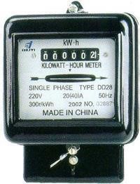 | Figure 1. Traditional Energy Meter |
2. System Design
- This section deals with overall working and system design of this project. Our main aim is to send the power consumed by the customer directly to the utility without manual reading at the end of the month. The power consumed and its corresponding bill is then mailed to the customer. To simulate home wiring and meter w have used a simple circuit. Information is transmitted by modulating a continuous transmission signal by amplifying signal's strength or varying its frequency to add or take away data. The current flow through this circuit is measured using a current sensor which is analog and converted into digital using an ADC. The current value is obtained and the power is calculated using Raspberry Pi. This value is then sent to the database and stored and the total bill is calculated and email is generated for the respective user. So if a user wants to avail this service he/she should register and the pi is set up for the user and thereafter the working is as mentioned above. The user is also provided with a service of online payment of his bills and given deadlines. Failure of payment will be notified to the admin and he is authorized to take further actions. Admin also has privileges of viewing the new customers and updating the rates/unit consumption of power.
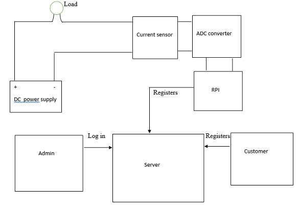 | Figure 2. Circuit diagram |
3. Hardware
3.1. Raspberry Pi
- The Raspberry Pi is a credit-card-sized computer that plugs into your TV and a keyboard. It is a capable little computer which can be used in electronics projects, and for many of the things your desktop PC does, like spreadsheets, word. processing, browsing the internet, and playing games.
3.2. Analog-to -digital Converter
- An analog-to-digital converter, or ADC as it is more commonly called, is a device that converts analog signals into digital signals. Analog information is transmitted by modulating a continuous transmission signal by amplifying a signal's strength or varying its frequency to add or take away data.
3.3. Current Sensor
- A current sensor is a device that detects electric current (AC or DC) in a wire, and generates a signal proportional to it. The generated signal could be analog voltage or current or even digital output. It can be then utilized to display the measured current in an ammeter or can be stored for further analysis in a data acquisition system or can be utilized for control purpose. In the project we use acs 712.
3.4. Resistor
- A resistor is a passive two-terminal electrical component that implements electrical resistance as a circuit element. In electronic circuits, resistors are used to reduce current flow, adjust signal levels, to divide voltages, bias active elements, and terminate transmission lines, among other uses.
3.5. Adapter
- An adapter or adaptor is a device that converts attributes of one electrical device or system to those of an otherwise incompatible device or system. Some modify power or signal attributes, while others merely adapt the physical form of one electrical connector to another. In the project we use a 5v dc adapter.
4. Software
4.1. Angry ip Scanner
- Angry ip scanner is a very fast ip address and port scanner. It runs on Linux, Windows, and Mac OS X, possibly supporting other platforms as well. It can scan IP addresses in any range as well as any their ports. The gathered information may include the following: 1. Whether the host is up (alive, responding) or down (dead, not responding). 2. Average roundtrip time (of IP packets to the destination address and back) 3. Host and domain name (by using a DNS reverse lookup) versions of particular services running on the host open. 4. Filtered TCP and UDP ports.
4.2. VNC Viewer
- Also known as virtual network computing. VNC is a graphical desktop sharing system that uses the Remote Frame Buffer protocol (RFB) to remotely control another computer. It transmits the keyboard and mouse events from one computer to another, relaying the graphical screen updates back in the other direction, over a network. VNC is platform independent – there are clients and servers for many GUI-based operating systems and for Java. Multiple clients may connect to a VNC server at the same time. The VNC client (or viewer) is the program that represents the screen data originating from the server, receives updates from it, and presumably controls it by informing the server of collected local input. The VNC protocol (RFB protocol) is very simple, based on one graphic primitive from server to client ("Put a rectangle of pixel data at the specified X,Y position") and event messages from client to server. In the normal method of operation, a viewer connects to a port on the server. The server sends small rectangles of the frame buffer to the client.
5. Experimental Results
- The project obtained results can be divided into three parts namely: 1. Hardware Setup 2. Readings from the hardware3. Web dashboard for user interaction
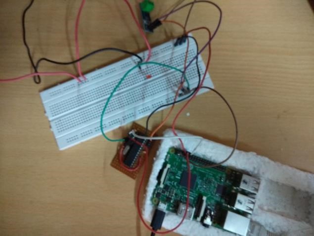 | Figure 3. Hardware setup |
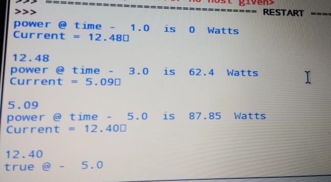 | Figure 4. Readings from current sensor |
 | Figure 5. Web page for customers |
6. Conclusions
- The main aim of this project is to reduce the man power involved in power management. It also avoids data loss. However, the initial setup will cost more than the existing mechanism. It provides better power management for the utility office as the values are directly sent from the meter and stored in their database. This data can be used in future to analyze the usage of power and take necessary measures to optimize power consumption. In addition to this, this mechanism can also provide self-analysis of power consumption of a user so can he/she can reduce the usage.